Note : Les descriptions sont présentées dans la langue officielle dans laquelle elles ont été soumises.
2123329
Backqrolmd
This invention relates to iron type golf clubs, and,
more particularly, to an iron clubhead which is formed from two
different materials.
An iron clubh~ad includes a blade, which includes the
club face for striking a golf ball, and a hosel, to which the
shaft i~ secured. A junction portion connects the ho~el and the
blade. Iron clubheads are conventionally forged or cast in a
single, integral piece from metal or metal alloy.
Some clubheads are formed from two or more different
materials. ~or example, a metal core can be covered with
fiber-reinforced composite material, or the face and back of the
clubhead can be formed from different ~aterials. In such cases,
however, the hosel and junction are generally formed integrally
with a portion of the blade.
Each numbered golf iron, for example a 5 iron, ha~ a
standard weigh~ which does not vary much ~e~ween various
manufacturers o~ golf cl~b~. A typical iron clubhead has about
78% of its weight in ths blade area and about 22% of its weight
in the junction area. Ball flight and di~tance is affected by
the weight of the blade and the manner in which the weight is
di~tributed in the blade. The weight in the hosel and the
junction area has little or no effect on the ball.
Some clubs have redistributed weight from the hosel to
th~ blade by forming opening or cutoutC in the hosel. However,
such openings interrupt the integrity of the hosel. Other clubs
have reduced the length of the hosel or eliminated the hosel.
However, the attachment of the Rhaft to the clubhead can be
adversely affected.
Su~ELa~y of the_Invention
The invention provides a compo~ite iron clubhead in
which the blade is for~ed of a fir~t material And the hosel and
2~ 2~329
hosel junction are formed from a second material which is less
dense than the first material. Weight is thereby taken out of
the hosel and junction and redistributed to the blade. The
additional weight in the blade will have an advantageous effect
on the flight and distance of the golf ball. The blade includes
a toe end and a heel end and a relatively flat bracket which
extends from the heel end. The bracket is provided with
openings, and the material of the junction surrounds the bracket
and extends through the openings.
DescriDtion of the DrawinGs
The invention will be explained in conjunction with an
illustrative embodiment shown in the accompanying drawing, in
which --
Figure 1 is a front elevational view of a clubhead
formed in accordance with the in~ention,
Figure 2 is a rear elevational view of the clubhead;
Figure 3 is a front elevational view of the blade of
the clubhead;
Figure 4 i~ a rear elevational view of the blade;
Figure 5 i~ a side elevational view of the blade taken
along the line 5-5 o~ Figure 3;
Figure 5 i5 a YieW similar to Figure 2 with the
junction portion of the clubhead broken away; and
Figure 7 is a view similar to Figure 2 showing the
bracket of the blade in dotted outline.
Descri~tion Qf S~ç~if~c E~kodiment
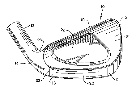
~ eferring first to Figures 1 and 2, an iron type golf
clubhead 10 includes a blade 11, a hosel 12, and a junction 13
which joins the hosel and the blade. The hosel is tubular or
cylindrical and is provided with a bore 14 which is adapted to
receive a conventional gol~ club shaft. The shaft is inserted
into the hosel and secured therein in ~h~ conventional manner.
-2-
-- ` 212~3~9
The blade 11 includes a toe end 15 and a heel end 16and a flat face 17 which extends from the toe end to the heel
end. A plurality of parallel grooves 18 are formed in the face
in the conventional manner. The blade also includes a top edge
19, a sole 20, and a back surface 21. The particular clubhead
illustrated includes a cavity 22 in the back surface. The
bottom of the junction 13 curves upwardly from the sole of the
blade, and the top of the junction includes a generally U-shaped
notch 23.
The grooves 18 are usually designed so that they extend
parallel to a ground plane G when the center o~ the sole rests
on the ground in the proper address position. The toe ends of
the grooves and the heel ends of the groove are aligned along
lines which extend perpendicularly to the grooves.
Referring now to Figures 3-5, the blade 11 is formed
separately from the junction and the hosel. The heel end o~ the
blade terminates in a flat end ~urface 25 which extends
perpendicularly to the face 17 and the grooves 18. A flat, thin
bracket 26 extends $rom the end surface 25 parallel to the face
17. A~ can be ~en in Figure 5, the thickness of the bracket i 3
con~tant along the length of the bracket and the thickness ot
the brack~t in a diraction perpendicular to the face 17 is le~-
than the thickne~s of the blade along the top edge 19.
The bracket has a curved botto~ edge 27 and a U-shap~d
top edga 28 which conform generally to the contour of the
junction 13. The bracket terminates in a straight end edge 29.
A plurality of openings 30 are for~ed in the bracket.
The blade 11 can be ~ormad by conventional forging or
ca~ting techniques. The bracket 26 is formed integrally wit~
the remainder of the blade, and, if necessary, suitable
finishing operations can be per~ormed on the bracket to obtain
the de~ired shape or openings. In the embodiment illustrated,
the entire bracket is generally planar and extends parallel to
--3--
212~329
the face 17. However, for irons which have an offset hosel, the
bracket can curve forwardly beyond the face 17 so that the
completed hosel will have the desired offset relative to th
blade.
The material of the junction 13 and hosel 12 is cast or
otherwise formed around the bracket 26 and abuts the flat end
surface 25 of the blade. During formation of the junction, the
molten or soft material of the junction flows through the
opanings 30 in the bracket to form a secure interconnection
between the junction and the bracket. The bore of the hosel may
be formed while the hosel is formed and extends substantially to
the end 29 of the bracket. Alternatively, the material of the
junction 13 and the hosel 12 can be joined to the blade at the ;~
~urface 25 by welding, brazing, epoxy, copper flash, or
mechanical fit.
The outer surface of the junction merges smoothly with
the outer ~urface of the blade, and a seam line 32 is formed
where the material of the junction meets the material of the
blade. If desired, the seam line can be buffed to render the
seam less perceptibl~. The seam line extends perpendicularly to
the grooves 18. The flat end surface 25 and the sea~ line 32
are spaced about 0.10 to 0.~0 inch, preferably about 0.15 inch,
from the heel ends of the grooves and are substantially aligned
with the inter~ection P (Figure 1) between the axis or
centerline ~ of the hosel and the ground plane G.
The blade is formed from a relatively dense material,
and the junction and hosel are formed from a le~s dense material
so that the weight of the junction and hosel is less than the
weight of the junction and hosel of a conventional club. The
weight of the blade can therefore be in~reased while maintaining
the ovsrall weight of the clubhead within the traditional
range. The extra weight in the blade can be used to increase
the perimeter weighting o~ the cavity backed blade and/or
increase the m~ss behind the sweetspot of the face.
--4--
2125329
The material of the bladé can be corrcsion resistant
~tainless steel, beryllium copper alloy, or other conventional
clubhead materials. The material of the hosel and junction can
be aluminum, titanium, composite material such a~ fiber
reinforced resin, e.g., graphite fibers and epoxy resin, or
other material which is lighter than the material of the blade.
A typical number iron clubhead has about 78-80% of its
weight in the blade area and about 20-22% of its weight in the
hosel and junction area. By forming the clubhead in accordance
with ~he invention, the weight distribution of the clubhead can
be changed so that a substantially higher percentage of the
weight of the clubhead is in the blade. For example, the weight
distribution can be varied as desired so that from 80% to up to
about 95% of the weight is in the blade and only about 20% to 5%
is in the hosel and junction area. More preferably, the weight
of the blade is between about B5 and 95% of the total weight of
the clubhead, and the weight of the hosel and junction is
between about 5 and 15% of the total weight. Even more
pr~ferably, the weight distribution is about 90% of the blade
and about 10% in the hosel/junction area.
Table I describes the weight distribution of a prior
art set o~ conventional Wilson Ul~ra iron clubheads.
TA8L~ I
Conventional Clubhead
No. of Total Weight Weight in % of Weight % of Weigh
Iron Weiaht in_~lade Hosel/Junction in Blade _ in Hosel
(grams) (grams) (grams)
1 236.2 185.3 50.9 78.45 21.55
2 242.3 ~91.55 50.75 79.05 20.95
3 247.2 195.5 51.7 79.09 20.91
4 253.8 200.7 53.1 7g.08 20.92
258.5 202.9 55.6 78.49 21.51
6 26~.3 212.5 53.8 79.80 20.20
7 271.4 216.25 55.15 79.68 20.32
8 279.2 220.70 58.5 79.05 20.95
9 286.7 226.25 60.45 78.92 ~1.08
PW 296.4 235.~5 61.35 79.32 20.20
Sand
W~dgQ 322.9 253.8 69.1 78.60 21.40
60-
Wedge 315.2 245.35 69.85 77.84 22.16
2125~29
, ~
By varying the materials which are used for the blade
and for the hosel and junction, the weight distribution in the
blade and the hosel/junction can be varied as desired while
maintaining the overall weight of the clubhead within the
standard rang For example, the clubheads in Table I were made
from steel which has a density of 0.28 pounds per cubic inch.
An advantageous material for the hosel/junction area is A206
aluminum, which has a density of only 0.101 pounds per cubic
inch.
Dimensions and weights which are referred to herein may
vary within standard manufacturin~ tolerances for cast and
forged clubheads, for example about + 2%.
While in the foregoing spe~i~ication, a detailed
description of a specific embodiment of the invention was set
forth for the purpose of illustration, it will be understood
that ~any of the details herein given may be varied considerably
by those skilled in the art without departing from the spirit
and scope of the invention.