Sélection de la langue

Search

Sommaire du brevet 2125590 

Énoncé de désistement de responsabilité concernant l'information provenant de tiers

Une partie des informations de ce site Web a été fournie par des sources externes. Le gouvernement du Canada n'assume aucune responsabilité concernant la précision, l'actualité ou la fiabilité des informations fournies par les sources externes. Les utilisateurs qui désirent employer cette information devraient consulter directement la source des informations. Le contenu fourni par les sources externes n'est pas assujetti aux exigences sur les langues officielles, la protection des renseignements personnels et l'accessibilité.

Disponibilité de l'Abrégé et des Revendications

L'apparition de différences dans le texte et l'image des Revendications et de l'Abrégé dépend du moment auquel le document est publié. Les textes des Revendications et de l'Abrégé sont affichés :

  • lorsque la demande peut être examinée par le public;
  • lorsque le brevet est émis (délivrance).
(12) Brevet: (11) CA 2125590
(54) Titre français: ACCESSOIRE SERVANT AU NETTOYAGE DES RANGEES DE PLANTATION
(54) Titre anglais: ROW CLEANING ATTACHMENT
Statut: Durée expirée - au-delà du délai suivant l'octroi
Données bibliographiques
(51) Classification internationale des brevets (CIB):
  • A01B 43/00 (2006.01)
  • A01C 05/06 (2006.01)
  • A01C 07/00 (2006.01)
(72) Inventeurs :
  • CLIFTON, KENNETH RALPH (Etats-Unis d'Amérique)
  • RYLANDER, DAVID JAMES (Etats-Unis d'Amérique)
(73) Titulaires :
  • DEERE & COMPANY
(71) Demandeurs :
  • DEERE & COMPANY (Etats-Unis d'Amérique)
(74) Agent: BORDEN LADNER GERVAIS LLP
(74) Co-agent:
(45) Délivré: 1998-07-28
(22) Date de dépôt: 1994-06-10
(41) Mise à la disponibilité du public: 1994-12-17
Requête d'examen: 1994-06-10
Licence disponible: S.O.
Cédé au domaine public: S.O.
(25) Langue des documents déposés: Anglais

Traité de coopération en matière de brevets (PCT): Non

(30) Données de priorité de la demande:
Numéro de la demande Pays / territoire Date
08/079,305 (Etats-Unis d'Amérique) 1993-06-16

Abrégés

Abrégé français

Accessoire servant à nettoyer les rangs de culture pour matériel de semis comportant un coutre monté entre deux roues plombeuses de circonférence uniforme, et à l'arrière de celles-ci. Ces roues sont inclinées indépendamment vers le bas dans le sol au moyen de ressorts en vue de retirer les résidus de culture de la ligne de semis du semoir. D'un diamètre supérieur à celui des roues plombeuses, le coutre est fixé de manière que son côté tranchant coupe les résidus de culture à mesure qu'ils sont tendus entre les roues plombeuses.


Abrégé anglais


A row cleaning attachment for seeding equipment
comprising a coulter mounted between and behind two press
wheels having a uniform circumference. The press wheels are
independently spring biased downwardly into contact with the
ground for holding and pulling the crop residue away from the
planting line of the planting unit. The coulter has a larger
diameter than the press wheels and is located so that the
cutting edge of the coulter cuts the residue material as it is
being tensioned between the press wheels.

Revendications

Note : Les revendications sont présentées dans la langue officielle dans laquelle elles ont été soumises.


The embodiments of the invention in which an exclusive
property or privilege is claimed are defined as follows:
1. A row cleaning attachment for seeding equipment, the
seeding equipment having a furrow opener defining a planting
line, the attachment comprising:
a pair of press wheels located upstream of the furrow
opener, the pair of press wheels straddle the planting line
and form a V-shaped configuration with an open vertex and an
open base, the open vertex lies on the planting line, the
press wheels engage crop residue located on either side of the
planting line and pull the crop material outwardly from the
planting line; and
a coulter is located behind and between the press wheels
along the planting line and passes through the open base of
the press wheels, the coulter is provided with an outer
periphery having a cutting edge that cuts crop residue
tensioned between the pair of press wheels.
2. A row cleaner attachment as defined by claim 1
further comprising two forwardly extending members on which
are pivotally mounted two pivot arms, each pivot arm has a
first end that is pivotally attached to one of the two
forwardly extending members and a second end on which is
rotatably mounted the press wheels.
3. A row cleaner attachment as defined by claim 2
further comprising a forwardly extending member on which is
rotatably mounted the coulter.
4. A row cleaner attachment as defined by claim 3
wherein the press wheels have a uniform circumference and ride
on the soil surface.
5. A row cleaner attachment as defined by claim 4
wherein each pivot arm is independently biassed downwardly by
two independent spring assemblies.
6. A row cleaner attachment as defined by claim 5
wherein each independent spring assembly is provided with an
adjustable bias set pin which contacts the spring assembly and
can be adjusted for adjusting the biassing force applied to
the pivot arms by the spring assemblies.
7. A row cleaner attachment as defined by claim 6
wherein each of the two forwardly extending members on which

the pivot arms are mounted is provided with a stop member for
engaging the pivot arms and preventing further downward
rotation of the pivot arms.
8. A row cleaner attachment as defined by claim 7
wherein each of the two forwardly extending members on which
the pivot arms are mounted is provided with at least two holes
in which the bias set pins are inserted.
9. A row cleaner attachment as defined by claim 8
wherein each spring assembly comprises two springs that
contact the bias set pin and the pivot arms.

Description

Note : Les descriptions sont présentées dans la langue officielle dans laquelle elles ont été soumises.

-' 2125~
A ROW CLEANING ATTACHMENT
BACKGROUND OF THE lNvl~;N~l~loN
1. Field of the Invention:
The present invention is directed to a row cle~n; ng
attachment to be used with agricultural seeding equipment for
cleaning crop residue from a very narrow strip of soil along
the planting line.
2. Background of the Invention:
Agricultural seeding equipment, such as row crop planters
and grain drills, maybe provided with row cleaning attachments
of the kind disclosed in U.S. Patent 4,785,890. Increasingly
farmers are switching to no-till or low-till residue
management practices in which fields are not plowed or tilled
to any appreciable degree between crops. Such practices put
added burdens on seeding equipment. For example, crop residue
and debris encountered by the seeding equipment may adversely
affect seed placement, seed/soil contact, seed emergence and
seed germination.
Double cropping soybeans after winter wheat is a popular
crop rotation system used in the southern portion of the
midwestern United States. The soybeans are typically planted
in freshly cut wheat stubble to preserve soil moisture at
planting and help control erosion. The freshly cut wheat
stubble is slippery and has no chance to weather or
deteriorate. As such it is difficult for the seed openers of
the soybean see~i n~ equipment to cut the stubble and large
amounts of crop residue can be hairpinned into the seed trench
causing poor seed/soil contact and poor see~in~ emergence. In
addition many double cropped beans are planted in narrow rows
(15 inch or smaller). Currently marketed row cleaners
displace too wide a band of residue and therefore are not
compatible with narrow row spacings. Farmers do not want a
wide bare strip of soil, as wide bare strips are susceptible
to rapid drying and crusting when planted in mid-summer.
SUMMARY
It is an object of the present invention to provide a row
cleaning attachment that only disturbs a very narrow strip of

-' 2123~9~
soil through which the furrow opener of the seeding equipment
passes.
The row cleaner of the present invention comprises two
independently spring biassed press wheels which fix the crop
residue and pull it outwardly from the planting line of the
planting unit. A coulter having a cutting edge is located
behind and between the press wheels for cutting crop residue.
Crop residue engaged by both wheels is tensioned by both
wheels pulling it outwardly. The coulter engages and cuts the
tensioned crop material. After the crop residue is cut by the
coulter, the wheels pull the cut crop material further away
from the planting line of the planting unit. The wheels only
clean a very narrow band along the planting line of the
planting unit, so only a very narrow area of soil is exposed
to the sun.
For pulling the crop residue outwardly from the planting
line, the press wheels are arranged in a V-shaped
configuration having an open vertex and an open base. The
imaginary vertex of the press wheels would lie on the planting
line. The press wheels themselves do not intersect the
planting line. The coulter projects into the V formed by the
press wheels through the base of the V. The outer periphery
edge of the coulter comprises a cutting edge that cuts crop
residue tensioned between the press wheels.
The press wheels have a uniform circumference and ride on
the surface of the ground on either side of the planting line.
The press wheels do not project into the ground.
BRIEF DESCRIPTION OF THE DRAWINGS
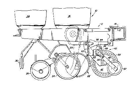
Figure 1 is a side view of a planting unit on which is
mounted the row cleaner attachment of the present invention.
Figure 2 is a top view of the planter attachment of the
present invention.
Figure 3 is an exploded perspective view of the press
wheels of the present invention.
DETAILED DESCRIPTION
Figure 1 discloses an agricultural planting unit 10. The
planting unit is provided with a parallel linkage 11 that is

.
212~9~
mounted to toolbar 12 by U-bolts 14 in a conventional manner.
The planting unit is provided with a seed bin 16 which directs
seeds to a seed meter 18. The seed meter 18 directs the
measured seeds to a seed tube 20 for placing the seeds into
the seed trench. The seed trench of formed by a furrow opener
22. Gauge wheels 24 control the depth of the furrow opener
22. Closing wheels 26 close the trench after the seed has
been deposited into the trench by the seed tube 20. The
illustrated planting unit is also provided with a pesticide
bin 28 for directing pesticide to the ground by applicator 30.
A suitable pesticide meter (not shown) controls the
application of the pesticide.
':
The above disclosed planter is of a relatively
conventional configuration. ~ypically a plurality of planting
units are mounted on toolbar 12 so that a farmer could plant
more than one row in a single pass over the field. Although
the present invention is illustrated as being mounted to a row
crop planting unit 10 it could also be mounted to other
seeding equipment like grain drills, and as such the invention
should not be limited to row crop planters. Each planting
unit, be it on a grain drill or row crop planter, defines a
planting line through which the furrow opener passes ~k;ng
the trench in which the seed tube deposits seed.
The row cleaning attachment 40 is bolted by bolts 42 to
the front of the planting unit 10 ; -~iately beneath the
parallel linkages. The row cleaning attachment 40 comprises
three forwardly ext~nd;ng members 43, 44 and 45 to which are
rotatably mounted bubble coulter 46, and to which are
pivotally mounted press wheel pivot arms 48 and 50. Press
3~ wheels 52 and 54 are rotatably mounted to the pivot arms 48
and 50 by bearing assemblies 56 and 58, respectively. It
should be noted that the present invention is illustrated as
having a bubble coulter but other coulter could also be used
and the invention is not limited to bubble coulters.
The pivot arms 48 and 50 are biassed downwardly by dual
spring assemblies 60 and 62. The first end of each pivot arm
is provided with an aperture 64 through which pivot pin 66 is

~' :
2 1 2 ~3~ 9 ~
lnserted. The pivot pin then extends through a first spring
68 of the respective dual spring assembly 60 or 62. After
passing through the first spring 68 the pivot pin is inserted
through an aperture 70 located on the respective forwardly
extending member 43 or 45. The pivot pin 66 then extends
through the second spring 72 of the respective dual spring
assembly 60 or 62. Washers 74 at each end of the pivot pin
together with locking pins 76 hold the assembly together.
The first spring 68 of each dual spring assembly 60 or 62
has a first end 78 that is inserted into elongated slot 80
located on the respective forwardly extending - h~rs 43 or
45. The second end 82 of the first spring 68 engages biassing
set pin 84 which is mounted in one of three holes 86 formed in
the forwardly extPn~;ng members 43 and 45. By moving the
biassing set pin 84 between the three holes 86 the downward
force on the pivot arms and thereby the press wheels can be
controlled.
The second spring 72 of each dual spring assembly 60 and
62 has a first end 88 which is inserted into a rigid extension
sleeve 90. Extension sleeve 90 is welded to the bottom of the
elongated slot 80. The extension sleeve reduces the nl hPr of
different parts needed for dual spring assemblies by allowing
the same springs to be used in each dual spring assembly. The
second end 92 of the second spring 72 engages biassin~ set pin
84 in the manner described above regarding the first spring
68.
The dual spring assemblies bias the press wheels 52 and ;~
54 downwardly against the ground surface. The mounting
assemblies 56 and 58 of the press wheels are configured first
hold and then pull crop residue away from the planting line
PL. The planting line PL is located between the press wheels.
The press wheels are arranged in a V-shaped configuration
having an open vertex. The imaginary vertex of the press
wheels would lie on the planting line PL.
The three forwardly extending members comprise two parts.
The first part is a U-shaped bracket 94 having forwardly
extending members 43 and 45. The bottom of each forwardly
, . ~ : - . .

-' 212~9(~
extending member 43 and 45 is provided with a stop plate 95.
The dual spring assemblies bias the pivot arms downwardly
against the stop plates 95. The second part is a support
member 96 having a bearing ~-h~r 98 for rotatably mounting
the coulter 46 to the member. Both parts are mounted to the
planting unit by bolts 42.
As shown in the drawings, the central rotational axis of
the coulter 46 is located behind the press wheels 52 and 54.
The outer periphery of the coulter 46 is provided with a
cutting edge 99 which is used to cut crop residue tensioned
between the press wheels 52 and 54.
As the planting unit 10 is pulled forward the press
wheels 52 and 54 contact the ground on either side of the
planting line PL. The press wheels 52 and 54 are rotated by
there contact with the ground. The press wheels 52 and 54
drag the crop residue outwardly from the planting line by
their V-shaped configuration. Crop residue contacting both
press wheels 52 and 54 is tensioned by the outward pull of
both wheels. The cutting edge 99 of the coulter 46 contacts
the tensioned crop residue cutting it and allowing the press
wheels to pull the severed portions outward from the planting
line.
The invention should not be limited by the above-
described embodiment, but should be limited solely by the
claims that follow.

Dessin représentatif
Une figure unique qui représente un dessin illustrant l'invention.
États administratifs

2024-08-01 : Dans le cadre de la transition vers les Brevets de nouvelle génération (BNG), la base de données sur les brevets canadiens (BDBC) contient désormais un Historique d'événement plus détaillé, qui reproduit le Journal des événements de notre nouvelle solution interne.

Veuillez noter que les événements débutant par « Inactive : » se réfèrent à des événements qui ne sont plus utilisés dans notre nouvelle solution interne.

Pour une meilleure compréhension de l'état de la demande ou brevet qui figure sur cette page, la rubrique Mise en garde , et les descriptions de Brevet , Historique d'événement , Taxes périodiques et Historique des paiements devraient être consultées.

Historique d'événement

Description Date
Inactive : Périmé (brevet - nouvelle loi) 2014-06-10
Inactive : CIB de MCD 2006-03-11
Accordé par délivrance 1998-07-28
Inactive : Taxe finale reçue 1998-02-10
Préoctroi 1998-02-10
Un avis d'acceptation est envoyé 1997-09-15
Lettre envoyée 1997-09-15
Inactive : Dem. traitée sur TS dès date d'ent. journal 1997-09-10
Inactive : Renseign. sur l'état - Complets dès date d'ent. journ. 1997-09-10
Inactive : CIB en 1re position 1997-08-11
Inactive : CIB enlevée 1997-08-11
Inactive : CIB attribuée 1997-08-11
Inactive : Approuvée aux fins d'acceptation (AFA) 1997-08-07
Demande publiée (accessible au public) 1994-12-17
Exigences pour une requête d'examen - jugée conforme 1994-06-10
Toutes les exigences pour l'examen - jugée conforme 1994-06-10

Historique d'abandonnement

Il n'y a pas d'historique d'abandonnement

Taxes périodiques

Le dernier paiement a été reçu le 1998-06-09

Avis : Si le paiement en totalité n'a pas été reçu au plus tard à la date indiquée, une taxe supplémentaire peut être imposée, soit une des taxes suivantes :

  • taxe de rétablissement ;
  • taxe pour paiement en souffrance ; ou
  • taxe additionnelle pour le renversement d'une péremption réputée.

Les taxes sur les brevets sont ajustées au 1er janvier de chaque année. Les montants ci-dessus sont les montants actuels s'ils sont reçus au plus tard le 31 décembre de l'année en cours.
Veuillez vous référer à la page web des taxes sur les brevets de l'OPIC pour voir tous les montants actuels des taxes.

Historique des taxes

Type de taxes Anniversaire Échéance Date payée
TM (demande, 3e anniv.) - générale 03 1997-06-10 1997-06-09
Taxe finale - générale 1998-02-10
TM (demande, 4e anniv.) - générale 04 1998-06-10 1998-06-09
TM (brevet, 5e anniv.) - générale 1999-06-10 1999-06-09
TM (brevet, 6e anniv.) - générale 2000-06-12 2000-06-09
TM (brevet, 7e anniv.) - générale 2001-06-11 2001-06-08
TM (brevet, 8e anniv.) - générale 2002-06-10 2002-06-07
TM (brevet, 9e anniv.) - générale 2003-06-10 2003-06-09
TM (brevet, 10e anniv.) - générale 2004-06-10 2004-05-25
TM (brevet, 11e anniv.) - générale 2005-06-10 2005-05-20
TM (brevet, 12e anniv.) - générale 2006-06-12 2006-05-17
TM (brevet, 13e anniv.) - générale 2007-06-11 2007-05-17
TM (brevet, 14e anniv.) - générale 2008-06-10 2008-05-20
TM (brevet, 15e anniv.) - générale 2009-06-10 2009-05-19
TM (brevet, 16e anniv.) - générale 2010-06-10 2010-05-17
TM (brevet, 17e anniv.) - générale 2011-06-10 2011-05-17
TM (brevet, 18e anniv.) - générale 2012-06-11 2012-05-17
TM (brevet, 19e anniv.) - générale 2013-06-10 2013-05-17
Titulaires au dossier

Les titulaires actuels et antérieures au dossier sont affichés en ordre alphabétique.

Titulaires actuels au dossier
DEERE & COMPANY
Titulaires antérieures au dossier
DAVID JAMES RYLANDER
KENNETH RALPH CLIFTON
Les propriétaires antérieurs qui ne figurent pas dans la liste des « Propriétaires au dossier » apparaîtront dans d'autres documents au dossier.
Documents

Pour visionner les fichiers sélectionnés, entrer le code reCAPTCHA :


Pour visualiser une image, cliquer sur un lien dans la colonne description du document (Temporairement non-disponible). Pour télécharger l'image (les images), cliquer l'une ou plusieurs cases à cocher dans la première colonne et ensuite cliquer sur le bouton "Télécharger sélection en format PDF (archive Zip)" ou le bouton "Télécharger sélection (en un fichier PDF fusionné)".

Liste des documents de brevet publiés et non publiés sur la BDBC .

Si vous avez des difficultés à accéder au contenu, veuillez communiquer avec le Centre de services à la clientèle au 1-866-997-1936, ou envoyer un courriel au Centre de service à la clientèle de l'OPIC.

({010=Tous les documents, 020=Au moment du dépôt, 030=Au moment de la mise à la disponibilité du public, 040=À la délivrance, 050=Examen, 060=Correspondance reçue, 070=Divers, 080=Correspondance envoyée, 090=Paiement})


Description du
Document 
Date
(aaaa-mm-jj) 
Nombre de pages   Taille de l'image (Ko) 
Revendications 1997-05-20 2 73
Abrégé 1995-06-07 1 21
Revendications 1995-06-07 2 72
Dessins 1995-06-07 3 142
Description 1995-06-07 5 254
Revendications 1998-05-24 2 73
Revendications 1998-05-31 2 73
Revendications 1998-06-08 2 73
Dessin représentatif 1998-07-23 1 19
Avis du commissaire - Demande jugée acceptable 1997-09-14 1 164
Correspondance 1998-02-09 1 31
Paiement de taxe périodique 1996-06-06 1 70
Demande de l'examinateur 1996-11-28 1 45
Correspondance de la poursuite 1997-04-01 13 1 322
Correspondance de la poursuite 1997-04-01 2 59
Correspondance de la poursuite 1994-06-09 5 205