Note : Les descriptions sont présentées dans la langue officielle dans laquelle elles ont été soumises.
- 1 2126378 ~ ~-
; ~,
The present invention relates to a process and an
apparatus for activating carbon-containing material.
In recent years, activated charcoal, due to its
properties as an adsorbent material with inert
5 characteristics, has been used increasingly in the most
disparate fields, such as for example:
-- in the processing of potable, process and waste
water, where activated charcoal effectively removes odors
and tastes as well as residues of colors and dissolved
lo organic substances;
-- in the purification of air and gases, such as for
example in conditioning systems, in sewage systems, and in
chemical processes;
-- in the preparation of filters for masks, hoodsl
15 cigarettes, etc.;
-- in the food industry, in processes for the
decolorization of sugar, glucose, vegetable oils, fermenting
alcoholic beverages, juices, etc.;
-- in the pharmaceutical industry, to purify raw
20 materials and intermediate compounds;
in the chemical industry, to purify colors and
plasticizers, organic acids, for galvanic deposition baths,
in recovering gold from residues of mining processes, in
catalysis, both as a medium (hydrogenation, desulfurization,
25 vinyl chloride synthesis) and as an actual catalyst
(phosgene, vinyl acetate, etc.);
-- for use as a medicine, on its own or in association
with antiseptics, digestive ferments, etc., in the
2 2~2~378
preparation of tablets or capsules.
Its many uses, combined with the increasingly strict
limits set by new statutory provisions in the field o~
pollution, have caused a considerable increase in the use of
5 activated charcoal. One should also add that processing with
activated charcoal is often cheaper than other purifying
systems, such as thermal or catalytic reheating, scrubbing,
or other adsorption techniques, when the level of the
impurities is less than a few hundred parts per million.
Activated charcoal is obtained by activating carbon
based material derived essentially from bituminous coals,
peat, coconut shells, wood, sawdust, etc. by means of
activation processes which are designated as chemical or
physical.
Chemical activation uses the particular action of some
inorganic compounds (activating agents) during the
carbonization step, which is performed at temperatures of
400 to 600C. The material is initially impregnated with
appropriate chemicals which, when heated, release oxidizing
20 gases that degrade the organic molecules. The main known
activating agents are zinc chloride and phosphoric acid;
positive results have been obtained by using sulfates or
phosphates of alkaline metals, potassium thiocyanide, and
manganese sulfide. Chemical activation is about to be
2s abandoned since the step for the removal of the activating
agent entails considerable ecological problems.
Physical or thermal activation is performed with
gaseous activating agents that selectively oxidize the
carbon-containing material. The treatment, which is usually
30 preceded by carbonization of the raw material so as to
- ` 3 2~2~378
reduce its content of volatile substances, uses air, water
vapor or carbon dioxide. During the activation step, part of
the carbon is burned, consequently increasing porosity.
Oxidation with air is performed at low temperatures,
5 but the exothermic nature of the reaction entails difficulty
in managing it; it is used to produce charcoals having a low
level of activity. Conversely, since treatment with C02 or
H20 is endothermic, it is easy to control and thus more
widely used despite its high process temperatures.
Presently, activated charcoal is almost entirely
produced with the thermal process, using water vapor a~ a
reagent. Thermal activation is performed in reactors
normally used in gas-solid reactions in the chemical
industry in general. Among these reactors, those currently
15 most used are multiple-hearth furnaces, tubular rotary
furnaces and fluid-bed furnaces.
Multiple-hearth furnaces are those most widely used to
activate charcoal and are constituted by a metal tower which
is internally lined with refractory material and in which
20 various tables are arranged. A shaft rotates at the vertical
axis of the tower and has rotating arms fixed thereto; said
arms have inclined vanes which have the purpose of moving
the material. The charcoal, which is loaded from above,
encounters the steam, which is supplied from the lower part,
25 and falls through holes onto the underlying tables since it
is moved by the vanes. These reactors have the advantage of
well-established technology and high reliability, but they
have several problems, including poor efficiency in
reaction, which is linked to the particular type of contact
30 between the phases occurring in this reaction. Very poor
- 4 2126~78
contact leads to long permanence times, with consequent
large volumes and low specific productivity. Furthermore,
apparatuses using multiple-table furnaces are very large and
complex and therefore require large investments and onerous
5 maintenance operations.
Rotary tubular reactors are instead essentially
constituted by a rotating cylinder, at the ends whereof the
charcoal and the steam are loaded in countercurrent. These
apparatuses are simple but have the drawback that they do
~o not provide good contact between the reagents, and this
leads most of all to low productivity.
Fluid-bed furnaces have been adapted to this production
in recent years. These furnaces are internally lined with
refractory material, and a porous plate is arranged in the
15 lower portion of the furnace; the charcoal is fed onto said
plate and the steam passes therethrough. The bed, during
agitation, practically doubles its height, providing
excellent contact between the phases. This type of apparatus
offers, among its many advantages, considerable temperature
20 uniformity, highly effective gas-solid exchange and
therefore low permanence times and considerable potential.
On the other hand, the fluid bed has, among its
disadvantages, the fact that it fragments the product, that
it creates considerable erosion problems inside the reactor,
25 and that it furthermore requires high investment costs.
In addition to the above listed specific disadvantages,
these known types of apparatus for the thermal activation of
charcoal have the drawback of working by direct heat
exchange. The hot fumes that must sustain the endothermic
30 nature of the reaction in fact strike the charcoal directly.
21 26378
Excellent heat exchange is obtained in this manner, but on
the other hand there is the problem of high specific
consumption of charcoal, due to its partial combustion with
any excess oxygen contained in the hot fumes. Furthermore,
5 there is a considerable expenditure of enargy, since it is
necessary to have a reheat unit downstream of the furnace,
where the process gases must be treated in order to provide
the environmental protection conditions required by
applicable statutory provisions.
lo The aim of the present invention is to solve the
problems described above with reference to known types of
apparatus and process for the thermal activation of charcoal
by providing a process and an apparatus for activating
carbon-containing materials that is highly productive with
15 low investment costs.
Within the scope of this aim, an object of the
invention is to provide an apparatus that ensures excellent
steam-charcoal contact with consequent high reaction
efficiencies.
Another object of the present invention is to provide
an apparatus that entails a reduced consumption of charcoal,
with respect to conventional apparatuses, during the
activation reaction.
Another object of the invention is to provide an
25 apparatus for activating carbon-containing materials that
has considerably lower running costs than known apparatuses.
Another object of the invention is to provide an
~pparatus which is structurally simple, dimensionally
compact, and very simple in operation.
6 212~37~
Another object of the invention is to provide an
apparatus that allows to act independently on the reaction
parameterC, i.e. temperatures, permanence time of the
material in the reactor, and weight ratio between the
5 reagents.
With this aim in view, as well as these objects and
others which will become apparent hereinafter, there is
provided, according to the present invention, an apparatus
for activating carbon-containing material, characterized in
10 that it comprises: means for feeding the carbon-containing
material to be activated into a drum-shaped reactor which is
arranged so that its axis is substantially horizontal and
has means for moving the material around and along its axis;
heating means arranged outside said reactor; means for
, 15 injecting a stream of superheated steam inside said reactor;
and means for discharging the activated carbon-containing
¦ material outside said reactor.
Further characteristics and advantages of the apparatus
according to the present invention will become apparent from
2Q the following detailed description of a preferred but not
exclusive embodiment thereof, illustrated only by way of
non-limitative example in the accompanying drawings,
! wherein
figure 1 is a schematic view of the apparatus according
25 to the present invention;
figure 2 is a schematic view of the drum-shaped reactor
of the apparatus according to the invention and of the
heating means;
figure 3 is a schematic and enlarged-scale sectional
'`.:~- ''
7 2126378
view of figure 2, taken along the plane III-III;
figure 4 is a view of a detail of the heating means of
the drum-shaped reactor;
figure 5 is a schematic sectional view of ~igure 2,
5 taken along the plane V-V.
:,
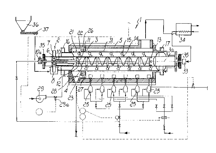
With reference to the above figures, the apparatus
according to the present invention, generally designated by
the reference numeral 1, comprises means 2 for feeding the
carbon-containing material to be activated into a drum-
lo shaped reactor 3 which is arranged so that its axis issubstantially horizontal and has means for moving the
carbon-containing material around and along its axis 3a. The
apparatus comprises heating means which are arranged outside
the drum-shaped reactor 3, means for injecting a stream of
15 superheated steam inside the reactor 3, and means for
discharging the activated carbon-containing material outside
the drum-shaped reactor 3.
The apparatus according to the present invention also
advantageously comprises means for preheating the carbon-
20 containing material to be activated before introducing it inthe reactor 3.
Conveniently, the means for preheating the carbon-
containing material to be activated are constituted by a
preheating drum 4 which is arranged coaxially inside the
25 drum-shaped reactor 3.
The preheating drum 4 and the reactor 3 are rigidly
coupled together in their rotation about the common axis 3a,
are rotatably supported about said axis 3a, and are
partially accommodated inside a heating muffle 5.
8 21 2 63 78
The axial ends of the drum-shaped reactor 3 protrude
from the heating muffle 5, and the axial ends of the
preheating drum 4 protrude from the axial ends of the
reactor 3. Loading ports 6 are formed in the skirt of one of
5 the end regions of the preheating drum 4 that protrude from
the reactor 3 and are distributed around the axis 3a: the
carbon-containing material to be processed passes through
said ports and is introduced in the preheating drum 4.
The means for introducing the carbon-containing
lo material in the preheating drum 4 are preferably constituted
by a wheel 7 which is fixed coaxially around the preheating
drum 4 at the loading ports 6. Said wheel 7 is partially
immersed, with its lower portion, inside a tank 8 for the
carbon-containing material to be processed and, as shown in
15 greater detail in figure 5, has a plurality of vanes 9
extending along substantially spiral-shaped paths that
converge towards the preheating drum 4, so that by rotating
the reactor 3 and the preheating drum 4 about the axis 3a,
the vanes 9 pick up the carbon-containing material that is
20 present in the tank 8 and lift it, conveying it by gravity
to the loading ports 6 of the preheating drum 4.
A screw feeder 10 is accommodated in the portion of the
preheating drum 4 that lies between the loading ports 6 and
the muffle 5; said screw feeder is arranged coaxially with
25 respect to the preheating drum 4 and is driven by means of
an appropriate variable-speed motor lOa arranged outside the
preheating drum 4, so as to cause the advancement of the
carbon-containing material introduced in the first portion
of the preheating drum 4.
Means for moving the carbon-containing material around
212~378
and along the axis 3a are provided inside the preheating
~ drum 4. Said movement means are appropriately constituted by
I a continuous or discontinuous cylindrical helix 11 which is
fixed to the internal surface of the preheating drum 4.
Inside the preheating drum 4 there are also means for
heating the carbon-containing material that has been
introduced said means are advantageously constituted by a
burner 12 which is arranged at the axis 3a and is supplied
through a duct that passes coaxially through the shaft of
lo th~ screw feeder lo.
Discharge ports 13 are formed proximate to the opposite
end of the preheating drum 4, in any case still inside the
muffle 5, and connect the preheating drum 4 to the inside of
the reactor 3.
¦ 15 Means for moving the carbon-containing material aroundand along the axis of the reactor are provided inside the
¦ reactor 3 as well. :
, In practice, the reactor 3 is constituted by a chamber ~1
¦ that has an annular cross-section and runs around the
120 preheating drum ~, and the means for moving the carbon-
containing material are constituted by vanes 14 which are ~ -~
arranged so as to form a continuous or discontinuous
cylindrical helix and are fixed to the outer surface of the
preheating drum 4. Advantageously there are also auxiliary
25 vanes 15 which are fixed to said vanes 14.
on the outside of the muffle 5 there are means for
rotating the reactor 3 of the preheating drum 4 at variable
speed about the axis 3a. More particularly, the drum-shaped
reactor 3 has, at its axial ends, regions 16 and 17 having
30 an increased diameter which rest on motorized rollers 18 and
212~378 ~ ~
on idler rollers 19. The rollers 18 are rotated about their
axis, for example by means of variable-displacement
hydraulic motors, and rotate the drum-shaped reactor 3 by
direct contact. The idler rollers 19 are appropriately
5 mounted on a carriage 20 that can slide parallel to the axis
3a so as to compensate for the axial elongations of the
drum-shaped reactor 3 caused by its heating.
The drum-shaped reactor 3 has, proximate to its axial
end which lies opposite to the end proximate to which the
10 ports 13 for discharge into the preheating drum 4 are
arranged, discharge ports 21 through which the activated
carbon-containing material and the reaction gases are
removed from the drum~shaped reactor 3. More particularly,
the discharge ports 21 are formed inside the heating muffle
15 5 in a chamber 22 which is separated from the region of the
muffle in which the means for heating the drum-shaped
reactor 3 are located. The chamber 22 where the gas
separates from the activated charcoal is provided, in a
downward region, with a port 23, and a hopper 24 for
20 collecting the material delivered by the reactor 3 is
provided at said port 23.
The means for heating the drum-shaped reactor 3 are
constituted by a plurality of burners 25 which are arranged
inside the heating muffle 5 in a region which, as mentioned,
25 is separated by means of a partition 26 from the chamber 22
in which the processed material is discharged.
Conveniently, the gases produced by the reaction of the
activation of the carbon-containing material are also used
to heat the reactor 3. The chamber 22 is in fact connected
30 to the region of the muffle that accommodates the burners 25
11 2126378
through passages 27 which are shaped like an ejector body; a
comburent gas, such as for example air or oxygen, is
injected through said passages 27.
As illustrated in particular in figure 4, coaxially to
5 the passages 27 there is a nozzle 28 which is supplied with
the comburent gas by an impeller 29. The aperture of the
nozzle 28, and therefore the flow-rate of the comburent gas,
as well as its pressure, are adjustable in a per se known
manner, for example by means of a threaded rod 30 and an
lo adjustment valve 29a, from the outside of the heating muf~le
5. In practice, the passages 27 and the nozzles 28 form true
e~ectors that extract the gases produced by the activation
reaction from the reactor 3 and feed them into the heating
muffle 5, burning them.
The means for injecting the stream of superheated steam
inside the reactor 3 are constituted by a plurality of ducts
31 which are connected to the outer surface of the drum-
shaped reactor 3 and end in the drum-shaped reactor 3
through holes 32 formed in the skirt of the reactor 3
20 proximate to the discharge ports 13 of the preheating drum 4
so that the carbon-containing material, during its
advancement inside the reactor from the ports 13 toward the
discharge port 21, is struck by the stream of steam flowing
in the same direction. The ducts 31, which are appropriateIy
25 shaped to compensate for thermal expansions, are connected
to a rotating coupling 33 which is mounted on the end of the
preheating drum 4 which is opposite to the end where the
carbon-containing material is loaded. The rotating coupling
33 is connected to a steam generator 34 which can be heated
30 by means of the fumes that leave the heating muffle 5, which
12 2126378
have an enthalpic content that is sufficient to ensure the
production of the amount of steam required for the
activation process.
Advantageously, to prevent the assembly constituted by
5 the reactor 3 and by the preheating drum 4 from undergoing
excessive flexural deformations due to the high temperatures
of the process, the axial ends of the preheating drum 4 are
appropriately pre-loaded with weights 35.
For the sake of completeness in description, it should
10 be noted that the carbon-containing material to be processed
is conveyed t~ the tank 8 by virtue of known means, such as
for example a loading hopper 36 assisted by a screw feeder
37, whereas the activated carbon-containing material is
removed from the port 23 and subjected to cooling cycles in
15 a per se known manner.
The operation of the apparatus according to the present
invention is as follows.
Due to the combined action of the rotary motion of the
preheating drum and of the presence of the helix 11, the
20 carbon-containing material introduced in the preheating drum
4 advances along said preheating drum 4 up to the discharge
ports 13, thus preheating. It should be noted that the
preheating of the material inside the preheating drum 4
occurs directly.
Through the ports 13, the preheated carbon-containing
material passes into the drum-shaped reactor 3, where it
makes contact with the superheated steam and gradually
advances in~ide the reactor 3 in the opposite direction with
respect to the direction followed inside the preheating drum
30 4. The vanes 14 and 15 control the advancement of the
" 13 2126378
carbon-containing material during the activation reaction,
and at the same time their shape stirs the material, forcing
the steam to pass, during its motion, through the bed of
carbon-containing material, thus striking it directly. In
5 this manner the steam is prevented from flowing only over
the surface of the bed of material arranged on the bottom of
the reactor, facilitating contact between the reacting
phases. In particular, the vanes 15, by virtue of the
rotation of the reactor 3, lift the carbon-containing
10 material and then let it fall, helping to constantly renew
th~ surface of the layer of carbon-containing material that
is in contact with the steam and thus further improving the
effectiveness of the gas-solid exchange. A temperature
substantially comprised between 675C and 1100C is
15 maintained inside the reactor 3, and the activation reaction
occurs substantially at atmospheric pressure.
At the end of the path inside the reactor 3, the
reaction products, together with the excess steam, leave the
reactor 3 through the ports 21. Since the reaction gases are
20 constituted by combustible products, H2 and C0, they are
introduced in the combustion chamber of the muffle 5 through
the passages-ejectors 27 and are burned, providing the heat
required to sustain the endothermic activation reaction. In
practice, the operating conditions of reheating occur inside
25 the muffle 5. In practice, the burners 25 act as pilot
burners and are activated only during startup and to adjust
the reaction temperature, which is maintained, as mentioned,
preferably between 675C and 1100C.
The burned gases generated in the combustion chamber of
30 the muffle 5 leave the muffle 5 with a still high enthalpic
14 2126378
content that is used in the boiler 34 to generate the steam
required for the process. The steam that leaves the boiler
34 is saturated and enters the reactor 3 after flowing
inside the ducts 31, along which the steam is superheated.
In practice it has been observed that the apparatus and
the process according to the present invention fully achieve
the intended aim and objects, since they allow to achieve
high yields with low investment and running costs with
respect to conventional processes and apparatuses.
10 Furthermore, by indirectly heating the carbon-containing
material during the reaction it is possible to work with low
specific consumptions of charcoal according to the final
characteristics to be given to the product.
An additional advantage resides in the high efficiency
15 obtained by the particular reactor, which is furthermore
structurally very compact and constructively relatively
simple.
The apparatus and the process thus conceived are
susceptible to numerous modifications and variations, all of
20 which are within the scope of the inventive concept; all the
details may furthermore be replaced with other technically
equivalent elements.
In practice, the materials employed, as well as the
dimensions, may be any according to the requirements and the
25 state of the art.