Note : Les descriptions sont présentées dans la langue officielle dans laquelle elles ont été soumises.
` ~ 212717)
~ROTH PROCESS AND SYSTEM FOR CONTINUOUS MANUFACT~RE OF
POLYUP~ET~AlilE FOAM SLAB-STOCKS :
Field Of The Present Invent _n
The present invention relates to the production of
5. polymeric foams by using the frothing technique, and
more particularly is directed to a process and a system ~ --
for the continuous production of flexible and rigid
slab-stocks, normally used for providing panelling, soft
cushioning, and the like.
. ~ ~ .'~'!-
10. Backqround Of The Present Invention
Polymeric foams in particular polyurethane foams
are well known. In general their preparation requires -~
the miYing of reactive chemical components, such a~ a
polyol and an i~ocyanate, in the pre~ence of normally ;
15. used additives such as a suitable catalyst, a surfactant -
or cell control agent, and water which chemically reacts
with the isocyanate to produce the carbon dioYide for
~ :.
blowing the foam.
In the continuous production of fleYible foams and
20. pa~rticularly in the production of fleYible foams in
slab-stocks, as currently practised on conventional
machines, it is common practice to spread or pour a
thin layer of the miYture in a liquid state onto a
moving sheet substrate provided on a slightly s10ped
25. conveyor and then the foam is allowed to ri~e freely,
~ 2127~7 ~
due to reaction between the chemical component~, until
the total expansion of the foam is obtained. The foam is
then allowed to cure and thereafter i8 cros~-sawn into
blocks. Convention process and apparatus are described,
5. for esample, in U.S. Patent Nos. 3,325,823 and
4,492.664.
In order to avoid a situation where the liquid mix
underruning the foam, and to allow the production of
uniform blocks, use of a small slope, and high speed
10. for the conveyor and high chemical out put are usually
required. This results in costly and large ~pace
consuming machines, as well as in an excessively high
production rate and very large scale plants.
In an attempt to partially remedy the problems and
15. disadvantages involved by a conventional process, US-
Patent No. 3,786,122 sugge~ts an alternative foamingprocedure, in which liquid reactants are miYed and
introduced in the liquid state, at the bottom of a pre-
foaming trough. This allows the mixture to expand
20. upwardly causing the pre-expànded miYture to flow out of
the ves~el, on a channel-shaped sheet material
travelling on a conveyor device. Although this process
eliminates the use of reciprocating mixing head~ in the
production of a continuous slab of a polymeric foam,
25. nevertheless some problem~ arise due to "build-up~ of
-~ 2127~7 )
the foam in the trough which cause~ a progre~sive
narrowing or reduction of the useful volume of the
trough and consequently a reduction in the residence
time in the through. The partly expanded foam iB still
5. of a relatively high density and low viscosity and
limits the slope angle that can be used for the foaming
conveyor. Consequently, the risk of foam underrunning,
therefore, still exi~t~
Although the main object of the Patent No.
10. 3,788,122 was to employ a conveyor shorter in length,
running at a speed slower than the conveyor in a
conventional machine, the fact that the mixture emerging
from the vessel is still in a liquid state practically
prevents the speed and the length of the conveyor to be
15. reduced to any substantial extent. Therefore the
resulting slab-stock foaming machine was large and
still required large spaces. A Publication PU Handbook
G. HOERTEL Ed. Carl Hanser Verlang - 1985 pages 162-168
describes a further variation of the pouring technique
20. in the attempt to achieve an uniform lay-down ofl a
mixture of polyurethane component~ by a fixed mixhead.
This mixture being discussed by ~oertel is not a froth
nor does blowing occur. According to Hoertel the mixture
is spread onto the whole width of the conveyor by the
25. use of a distribution bar through which the mixture i~
-
212747,
delivered across a broad front. In the same manner the
resulting flow is similar to that resulting from the
trough used in the Patent No. 3,786,122; depending on
the volume of the distribution bar and the chemical
5. reactivity of the foam system, the mixture is delivered
onto a substrate as a clear ~no reaction) or an already'
creamy (reaction started) liquid. Consequently, density
and viscosity of the mixture still depend on the volume
of the distribution bar in which chemical foaming takes
10. place. Therefore, the distribution bar according to
Z~oertel does not substantially differ from the trough
system of IZl~l.S. Patent No. 3,786,122.
The frothing process i8 a well known technique in
polyurethane technology but not in the production of
15. slab stock foam. When frothing, a non-reactive inert
gas, or blowing agent, is mixed under pressure in a
liquid state or in solution with the polyurethane
chemical components in a mixer. The pressure is
subsequently released causing the frothing or pre~
20. expansion.,The vaporization of the blowing agent causes
the cells to grow and to foam the liquid reaction
mixture which cures to form an elastomer.
Typical blowing agents are the various
chlorofluorocarbons ~CFC), however certain environmental
25. problems are associated with the use of CFC materials.
2 1 2 7 ~ 7 ~ -
Therefore, many attempts have been made to produce
foamed polyurethane materials, by frothing with carbon
dioxide ~CO2)-
': ' '''
Carbon dioYide ~CO2) as non-reactive blowing agent,
5. in the frothing technique, has been suggested for
example by ~S Patents Nos. 3,184,419 and 5,120,770.
According to these two patents, the reaction
miYture is subjected to a pressure during mixing, to
maintain the blowing agent in the liquid state.
10. Thereafter the mixture is ejectea at atmospheric
pressure causing a turbulent vaporisation of the blowing
agent. Therefore, while the froth technique and the use
of an inert blowing agent incorporated in a liquid state
into the reaction mixture, allows the manufacture of a
15. foam of reduced density, nevertheless the cell structure
is of very inconsistent quality due to irregular shaped
and oversized cells or bubbles being present.
Although frothing with inert gas, in particular
CO2, is a well known potential technique, up to now no
20. successfully practicable frothing proces~ and system
have been suggested or discovered for use with and in
slab stock foam production.
In an attempt to solve the problem of slab stock
production without use of chlorofluorocarbon blowing
25. agents, and by using the frothing techniques, it has
~ 21 2 7~ 7~
been now discovered that the suitable release of the
mixture under pressure must take place under controlled
conditions. ~se of controlled conditions in the
production of polymeric foam~ positively influences the
5. growth of the cells during initial frothing eYpansion of
the misture, which is of importance in the production of
slab stock.
Presently, the need for a new foaming process and
system in the continuous manufacturing of flexible slab-
10. stock or other continuous foam production lines, in
which the frothing technique and a non-reactive blowing
agent could be practically usable, still eYists.
Ob~ects And Summarv Of The Present Invention
It is an object of the present invention to provide
15. a foaming process as referred above, by which it i8
possible to advantageously use a non-reactive liquid
blowing agent, preferably carbon dioxide, to froth,
without negatively affecting the cellular structure of
the foam, to provide an appropriate bubble f~ee
20. commercial product.
Another object of the present invention is to
provide a process and a system as referred to above, for
continuous foaming, in the production of flexible or
rigid slab-stocks, in which the frothing of the mixture
25. may be usefully performed under controlled conditions
.~ 8
~: 2127~ 7
allowing the spreading of the mixture on a moving
substrate in the form of a high viscous froth, without
involving turbulent vaporisation of the blowing agent.
This also permits production of a low density foam on
5. the order of 14 kg/m3 ~0.87 pcf).
A further object of the invention i8 to provide a
foaming process and system as referred to above, which
make possible the use of a low output plant running at
very low speeds thereby permitting foam lines that are
10. much shorter in length, in ~omparison to conventional or
known machines or production lines or plants, avoiding
limitations of the conventional systems while
maintaining the advantageous features thereof. This also
results in a dramatic reduction of exhaust, from a
15. shortened line operating at slower conditions, 80 that
the volume/hour of exhaust fumes that require scrubbing
or other cleaning effort prior to release is similarly
reduced. Equally important is the lessening of the
amount of factory air that needs to be conditioned
20. thereby reducing energy costs associated with slab stock
production.
The main objectives of the present invention are
therefore the elimination of cloro-fluoro carbons ~CFC)
and volatile organic compounds ~VoC) from the
formulation and substitution thereof with a le88
~ ` 9
212747~ -
expensive component, as well as production of soft, low
den~ity foam, with a very homogeneous cell structure,
free from large bubbles, pinholes and visible defects.
Contrary to general trends of conventional prior
5. art, the invention resides in mixing under pressure a
reactive blend of polymeric chemical components and an
inert, low boiling blowing agent, followed by frothing
the misture, prior to the start of any reaction, under
pressure-controlled conditions through a pressure
10. equalising and frothing device having an elongated
pressure-drop zone extending cross-wise to the moving
direction of a substrate. Then the frothing mixture is
restrained along a frothing passageway or cavity.
Thereafter, reaction of the frothed mixture begins. That
15. frothing passageway or cavity preferably has an output
aperture of larger area relative to the areà of the
aperture or outlet of the pressure-drop zone. According
to the invention, the pre~sure during mixing ranges
preferably from 5 to about 18 bar.
20. I The present invention is unique in the use of a
frothed form of the mixed chemical ingredients
comprising the polymeric foam to form slab stock. The
present invention is unique too in that it uses an
environmentally safe blowing agent to develop the froth
25. in the manufacture of slab-stock foam. Such foam slab
2127 ~7 -~
stock can be either flexible or rigid foam. The
invention employs a specially designed discharge or lay-
down head, called a gate bar, that uniquely aids the
mixed foam ingredients to froth. This frothing occurs in
5. a very controlled way by use of an elongated pressure-
drop zone, as part of the gate bar, and then by havingthe mixed, frothing material pass through a frothing
passageway or cavity wherein gaseous blowing agent is
gradually released into the frothing mixture prior to
10. discharge onto a moving substrate or conveyor. The
discharge head assures the frothed material is aistribu-
ted acros~ the width of the machine, either across a
substantial portion of the slab stock machine or across
a desired ~ortion thereof. The slab ~tock machine can
15. include a complete line or plant in which the frothed
foam will be permitted to chemically react, fully rise,
cure and then be cut into desired pieces.
From experimental tests has been al~o noted that
critical factors for producing a large foam block are
20. the equilibrium between foam profile angle, metering
machine's throughout, conveyor speed and formulation
characteristics, such as vi~co~ity build-up reactivity,
etc. According to present invention, because the
mixture, when reaction begins, is already viscou~ and
25. supports a steep ri~e angle, the foam'~ rising angle is
.i` ` 11 212747~ -
... ~
no longer a limitation on the proce~s conditions. The
froth being di~charged from the frothing cavity is a
homogeneous pre-expanding mixture with a sufficiently
high viscosity to avoid rise angle problems associated
5. with prior production equipment and flexible slab stock
lines. The viscosity is enough to sustain the production
of high blocks, that have fully reacted, even at very
slow speeds with steep fall plate angles. This condition
is accomplished by controlling the expansion phase of
10. the mixture, after the mix head, and allows for the
progressive release of the blowing agent in the reacting
mass. Accordingly, the four critical factors can be
varied to achieve the desired density rather than having
to be linked to a rigid set of parameter~ as was the
15. case with prior foam processes. The speed and size of a
line or plant can be tailored to the needs of the foam
manufacturer with speeds from 1 to 5 meters per minute,
.: .~ ~ , . :, . .
and lengths as short as 20 meters or less, rather than ~ ~
the more conventional length of about 100 meters. This ~ ;-
20. also permits a smaller volume per hour of exhaust to be ~ ~
. , .
dealt with and removed or scrubbed, simpler metering and
plant fabrication, foams made with C02, a smaller volume
of air to be conditioned, and very low densities down to
: :
about 14 kg/m3 or less.
~` 12
~ 2127~ 7~
Brief Description Of The Drawinqs -~
The invention and preferred embodiments thereof,
will be now described in great detail, with reference to
the accompanying drawings, in which:
5. Fig. 1 shows a system which operates according to
the frothing and foaming process of the present
invention;
Fig. 2 is an enlarged view of a frothing device -~
embodying the features of the present invention;
lO. Fig. 3 shows a second system embodying the features
of the present invention.
Fig.4 shows a further system embodying a modified
form of a frothing device;
Fig. 5 is an enlarged view of the frothing device
l5. of previous figure 4;
Fig. 6 shows an enlarged detail of a further
frothing device;
Fig. 7 shows another embodiment of the frothing
device according to the invention.
20. Detailed DescriPtion Of The Present Invention
The essential features of the invention are now
described in great detail with reference first to the
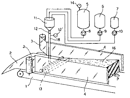
appended figures l and 2. As shown, the apparatus for
performing the process according to the invention, is
25. provided with two side walls 4 arranged to be
13 212747 )
perpendicular-to the conveyor 1. Continuous side papers
3 are arranged to run and move along the inside of each
side wall 4 in the production direction P ~see the
arrow) of the foam. A continuous paper sheet 2 slightly
~:
5. wider than the distance between the side walls 4, is fed
onto the conveyor 1 to provide a foaming path. The
excess layer at each side is turned up 80 as to form a
seal against the bottom edge of the side papers 3. The
. . .
bottom paper 2 and the side papers 3 effectively form a `
10. continuous open-topped trough, which could be, for ;~
example, about two meters wide by 1 meter high. The
- ,: . ....
conveyor 1 may be substantially arranged with a
horizontal disposition or, alternatively, it may be
formed with a small angle such as six degrees.
1~ The apparatus furthermore comprises a mixer 11
having an outlet 12 positioned at a level above the
conveyor 1, for feeding a mixture of reactive chemical
components to a frothing device, generally indicated at
. .,:
13, and schematically shown in the detail of figures 2
20. ' and 5. j ;
,,,
A pressure gauge 12' is provided at the outlet
spout 12 of the mixing device 11 to indicate the
pressure of mixed chemicals which leave the mixing
chamber through the outlet 12. Tank~ 5, 6 and 7 are
25. provided to hold the foam forming chemical components
14
21274~
such as a polyol and an isocyanate as well as
conventionally used chemical additives comprising a low
boiling blowing agent such as C02. From each of the
tanks, the chemical components and blowing agent are fed
5. to the mixer 11 by pipes and respective metering pumps
8, 9 and 10.
According to the embodiment as shown in figure 2,
the outlet spout 12 of the mixer 11 is connected by
tubing 18 to the mixture frothing device 13
10. transversally extending across the conveyor 1. The
frothing device 13 includes drop-pressure generating
means comprising an elongated drop-pressure zone in the
form of an elongated slot 17. It should be understood
that the purpose of the elongated pressure drop zone is
15. to provide a back-pressure and allow the mixing under
pressure of chemical components into the mixer 11 as
well as an equalization of the pressure in the same
frothing device, before the pressure reduction, to
prevent turbulent evaporation of the blowing agent
20. during frothing of the miYtUre. At the same time the
frothing device 13 allows frothing of the mixture under
restrained and pres~ure controlled conditions. The
frothing device 13 al~o assures that the resulting froth
is smoothly delivered onto the substrate 2, 3 while the
25. same mixture is flowing in the moving direction of the
~` ` 15
~--;` 2127~7~
conveyor device.
A~ referred above, and shown in the example of
figure 2, the pressure equalizing and frothing device 13
can, for eYample, comprise a tubular member defining an
5. elongated pressure equalizing chamber 21 having a
longitudinal asis. Chamber 21 is connected at one or
more feeding points, to the mixer 11 by at least one
tubing arrangement 18. The pres~ure equalizing or
tubular chamber 21 i~ provided with a pressure-drop
10. zone, for esample, in the form of the elongated slot 17
which eYtends longitudinally along one side of chamber
21. ~owever, the pressure drop zone could be formed from
other suitably shaped pressure-drop apertures for
flowing the mixture before frothing. As i8 shown in
15- figures 6 and 7, the discharge or gate bar could include
a ~eries of apertures of circular, oblong or rectangular
shape, or a series of elongated, but shorter, slots 80
long as the controlled conditions were produced. The
~lot or more precisely said pressure-drop sone 17 has a
20. restricted cross-sectional area sufficient to cause a
pressure reduction in the mixture emerging from the
chamber 21 during frothing, and a corresponding back
pressure in the mixing device 11 for the purpose
mentioned above.
25. Froth control, to obtain the controlled condition~
~ ` 16 212747~
!
that are aesirea during lay down of the froth, is
accomplished by use of an enlarged cavity, such as is
shown at 19 having an outlet aperture 20 from which the
frothing miYture is delivered onto the moving substrate.
5. The enlarged frothing cavity 19 has a suitable
configuration that will provide flow control over the
frothing mixture and in particular the cross-sectional
area of the output aperture 20 should be greater than
the cross-sectional area of pressure-drop zone, such as
10. the elongated slot 17, which provides communication
between the pressure equalizing chamber 21 and the
frothing cavity 19. The sectional area of the output
aperture 20 should range from ten to hundreds of times,
or more, the sectional area of the pressure-drop zone in
15. the form of the elongated slot 17.
In the embodiment shown in figure 1, the frothing
device 13 is delivering the frothed mixture onto the
substrate 2~3 which is moving on the conveyor 1 along a
substantially horizontal path. The conveyor may be
20. operated atla rate of about 1 to 5 meters per minute, 80
that the full block height may be achieved within a
range of about 1 to 8 meters from the deposit point of
the froth.
The above example of figure 1 refer~ to a system
2~ in which the foam rise upwardly from the bottom of the
17 2127~7~
: ; !
conveyor.
The example of figure 3 refers to a different
system in which the foam i8 allowed to froth onto a
downwardly sloping path which allows the length of the
machine to be greatly reduced. According to the
embodiment, the sloping angle of the conveyor, onto
which the frothing miYture is discharged, is not
critical due to the high viscosity of the froth emerging ~ -
from the frothing cavity. Therefore, underrunning does
10. not occur.
The continuous slab-stock machine of figure 3
continues to employ a main conveyor 1, together with the
associated side walls 4 and side and bottom papers 2 and
3, and that conveyor 1 is in a horizontal position. -~
15. This embodiment also includes a second driven
conveyor 25 inclined at an angle ~, for example of about
,- :.
30 degrees to the horizontal, and positioned between the
side walls and side papers in such a manner that its
lower end i8 i ediately above the main conveyor 1. The
pressure equalizing and frothing device 13, such as the
one described in EYample of figure 1 has been positioned
immediately above tbe upper surface of the conveyor 25
at its highest point. As an alternative to the conveyor
25, it is possible to use a slide surface, such a~ a
fall-plate for establishing the downwardly directed
: ,''. ' '
``` 18 212~47~
path. The angle ~ preferably can vary from about 10- to
about 40^ with a range of about 25- to about 30- being
the preferred angle.
The bottom paper 2 in this case, runs onto and down
the upper surface of the slanted conveyor 25 and then
onto and along the main conveyor 1.
A second continuous paper 22 runs under a roller 23
80 that it just clears the upper surface of the frothing
cavity 19 and in such a manner that the paper 22 rests
10. on and run8 with the top surface of the expanding foam
16.
Optional pressure plates 24 are fitted 80 as to
rest on the top side of the paper 22, if required, to
assist in shaping of the expanding foam.
15. Comparative tests have been conducted in the
continuous manufacture of slab-stocks by means of a
process ana a system according to present invention, in
comparison with a conventional system.
E:XA~?I.E:S ,,'' ~ ~
ExamPle 1 '
According to this comparative eYample, a
conventional continuous slab-stock machine as described
in Figure 1 was used except for the frothing device 13 ~ ;
which had been eliminated. A blend of chemicals,
.: .
25. identified as Blend A in the following Table 1, was made
!~: ` ,': ~ , ,' , ` . ' i.,
19 2~2747~
. . . ~.~ `
and introduced into tank 5. The 80:20 TDI, Part B, was
introduced into tank 6. Tank 7 held stannous octoate
catalyst, Part C.
The pumps 8, 9 and 10 were set to give the outputs
5. as defined in Table 1 for Parts A, B and C
respectively. Conveyor 1 was set to run at a speed of 5
meters per minute~
The foam-forming chemicals, coming from the mixer,
were allowed to pour from the mixing head outlet 12
lO. directly onto the paper 2. The reading on the pressure
gauge 12' was zero.
Expansion of the foam 16 started at a point along
the length of the conveyor 1 about 0.8 meters from the
mixing head 11. This represented a time of about 12
l5. seconds from mixing.
The foam was fully expanded by a point about 8
meter~ from the mixing head 11. This repre~ented a time
of about 105 seconds from mixing.The height of the foam
block after it had cured was 0.8 meters. The den~ity of
20. 1 a sample of foam cut from the block was 21.5 kg/m3. The
cell structure of the foam was of a consi~tent guality
with few irregular ~haped cell~, oversized cells or
voids being present.
''` 20 ~27~7j
TABLE 1
===================================================
Example~ Example
1 - 3 4
_____
Part~Output Output
by in in
weightkg/min kg/min :
=================================_============= :
PART A 120 24
Polyether Polyol, 3500 mw 100.00 :
Water . 4.50
Amine catalyst, Niax Al0.10 : :
Silicone, Tego~tab B2370 1.20
PART B ~ 62.4 12.5
80:20 TDI 55.2
PART C 0-25 0-05
The catalyst, ~tannous octoage 0.22
====================================================
NIAX i~ a Trade mark of ~nion Carbide
TEGOSTAB is a Trade Mark of T~ Gold~chmidt
~blowing agent having comparatively low co~t)
~ 21 2 127 47 j
!
ExamPle 2
According to this comparative example, the same
slab-stock foam machine as used in Example 1 wa~
utilized. In this case the blend of chemicals designated
5. Part A in Table 1, which was in the tank 5 was saturated
with carbon dioxide gas at pressure, by addition of a
quantity of liquid carbon dioxide. Sufficient liquid
carbon dioxide was added to achieve a pressure in tank
5, as indicated by the pressure gauge 14, of 6 bar.
10. The slab-stock foam machine was operated in the
same manner as described in Example 1.
This time, the chemicals left the miYing head
outlet tube 12 in the form of a turbulent froth. It was
also noticed that large bubbles of gas were forming in
15. the foam after being deposited on the bottom paper 2.
The pressure indicated by the pressure gauge 12' on the
outlet 12, was zero.
The foam expansion was completed at a distance of
about 7 meters from the mixing head 11.
20. I When the foam block had cured, it was found to have
a height of 0.9 metres, indicating that more expansion
had occurred than in Example 1.
The density of a sample of foam cut from the block
, . ~
was found to be 19 kg/m3.
25. The cell structure of the foam was inconsistent,
`` 22
212747::)
there being present in the foam large ovaloid voids or
pin holes up to 30 millimeters high by up to 10
millimeters diameter. The presence of these
irregularities in the cell structure made the foam
5. commercially unacceptable.
ExamPle 3
According to the invention the same slab-stock
frothing foam machine as used in Example 1 and 2 wa~
employed, except that a frothing device 13 according to
the invention, was fitted to the mixing head outlet ~12)
as to equalize the pressure of the foam formlng
chemicals across the width of the conveyor ~1) before
allowing them to froth by reducing their pressure on
passing through pressure drop zone 17 of the pressure
15. equalising chamber 21.
The pressure equalizing, frothing device
illustrated diagrammatically in Figure 2, consisted of a
1.9 meter length of steel tube 21 of internal diameter
millimeters. Along the length of the pressure
20. equalizing chamber 21, in the form of a steel tube was
cut a slot 17 of a height of O.S millimeter, and a
length of 1.85 meters. An inlet tube 18 was fitted onto
the slotted tube 21, which wa~ in turn connected to the
miYing head outlet 12.
25. A frothing cavity 19 in the form of a diverging
:.'.'~
~ ~ 23 212747~ -
diffuser~baffle 19 was attached to the outside of the
gate bar or the pressure equalization chamber 21 80 as
to form a diverging enclosed path from the elongated
slot 17 to the rectangular outlet 20 of the
5. diffuser/baffle. The dimensions of the outlet aperture
of frothing cavity were 1.85 meters wide by 0.2 meters
high. The length of the diffuser baffle form of the
frothing cavity from the slot to the outlet aperture was
0.5 meter.
10. The slotted tube, with the diffuser/baffle, was
fitted onto the slab-stock foam machine 80 that the
outlet aperture 20 was just above the bottom paper 2 and
facing down the conveyor 1 in the direction of
production as shown by arrow P.
15. The gate bar 60 could have the configuxation shown
in figures 6 and 7. In figure 6 the bar had a
rectangular outer shape as well as a rectangular cross-
sectional inner chamber 62. A series of elongated slots,as are shown at 64, 66 and 68, for esample, could be
20. used to provide the desired outlet from the gate bar 160
and the desired pressure drop. In figure 7 the gate bar
70 is provided with a circular cros~-~ectioned interior
chamber 72 from which a series of tubular outlet
apertures, as shown at 74, 76 and 78, for example,
25. axially extend in the flow direction to provide the
~'5~
~24 2127~7)
desired openings and pressure drop. ~ -
The slab-stock foam machine was run in the ~ame
manner as for Example 2. The pre~sure in the tank 5 was
again 6 bar as shown by pressure gauge 14; the pre~sure
in the miYing chamber was about 18 bar.
We have found that the pressure drop in the gate ~-
bar, or the pressure equalizing chamber 21 should be a
significant part of the total pressure drop from the
mixing chamber onwards.
10.This time, the foam emerged from the rectangular
aperture outlet 20 as a smooth froth. There was no -
evidence of large bubbles being present in the expanding
foam. The pressure indicated by the pressure gauge 12' -~
on the miYing head outlet tube 12 was 6 bar.
15.Foam expansion was completed at a distance shorter
than 7 meters from the outlet aperture of the outlet 20.
In consequence of the high viscosity of the froth,
according to the invention it is possible to reduce the
velocity of the conveyor and to dramatically reduce the
20. overall length of the line and therefore of the entire
plant in comparison to a conventional one, without -
causing underrunning problems. ;~
When the foam block had cured, it was found to have
a height of 1 meter. The density of a sample of foam cut
25. from the block was found to have a density of 17 kg/m3.
~ ~ .
~ 2 ~ 274 7~ -
The cell structure was fine and contained no large
voids. The foam quality was judged to be commercially
acceptable.
ExamPle 4
~.... ,
5., According to the invention the same chemical recipe
was used in Example 3, with 6 bar pressure in the tank
S containing the polyol blend/carbon dioxide mixture, in
pressure gauge 12'.
In this case, however, the outputs of the pumps 8,
10. 9 and 10 were reduced to one fifth of the outputs used
in Esample 3, as shown in Table 1 and the slot 17
reduced to a height of 0.4 mm.
The conveyor~ 1 and 21 were both run at a surface
speed of 1 meter/minute.
15. The expanding foam 16 in this case reached full
expansion at a distance of about 1.2 meters from the
outlet 20.
The height of the cured foam block was 1 meter. The
density of a sample of foam cut from the block was
20. measured to be 17 kg~m3. The cell ~tructure was fine and
similar to the foam made in Example 3. It contained no
large voids. The quality was judged to be commercially
acceptable.
The examples 3 and 4 in this specification clearly
25. demon8trate the efficiency of the process according to
` 26
`-`` 2~27~7;3 ~
the present invention by controlling the pre~sure drop
and the frothing of the mixture in continuou~ production
of polymeric foam material.
Example 5
5. The same chemical recipe has been u~ed in the
Example 4, except for the C02 content that ha~ been
increa~ed as described below. The embodiment ha~ been
modified in order to pump the liquid C02 in a continuous
way rather than pre-mixing it in the tank with the
10. polyol. A pump 54, ~hown in Fig. 4, has been added in
. ~
order to mix the liquid C02 from the tank 55 in the
polyol stream with the aid of a static mixer 530 A
pressure reducing valve 56 has been introduced in order
to assure that the pressure in the polyol line is
15. maintained that will keep the C02 in a liquid state at
the working temperature before the static mixer 53. The
,. . . .
liquid C02 ha~ been pumped in the polyol stream at an ;~
output to correspond to a weight ratio of 4% (C02 on
polyol~. The liquid C02 could be pumped as well in the
20. isocyanate ~tream. The slot 17 has been further reduced
in height to about 0.3 mm. The pressure gauge 12'
indicated a pres~ure of 15 bar~. All the other
parameter~ were maintained as in Example 4.
The height of the cures block wa~ 1.2 meters and
25. the den~ity was 14 kg/m3. The c:ell structure wa~ good.
`-~.' ~.~..
` , 27 2127~7~
Experimental tests conducted for a long time
demonstrated the real possibility to use C02 as primary
blowing agent in an effective manner, having a smooth
and homogeneous frothing of the reactant mixture on the
5. moving substrate, as well as the foaming of the material
while running on the conveyor at a comparatively low
velocity, thus resulting in a machine of substantially
reduced length and output in respect of machines which
make use of a conventional process or frothing
10. technique.
In conventional mechanical mixing of flexible
polyurethane foams, it is well known that it is
necessary to add small amounts of nucleating gas to the
liquid reactants during mixing. The purpose of the
15. nucleating gas is to provide nucleation sites for cell
formation at the start of foaming. Typically, nucleating
. ~ .
gas such as air or nitrogen would be added at a rate of
0.3 to 3 N litres per minute for a mixing throughput of
100 kg/minute of chemical reactants. ~ `
20. 1 According to the invention we have also found that
when liquid c?rbon dioxide is introduced into the liquid
reactants as an auxiliary blowing agent, it is still
advisable to add a nucleating gas. The gas, as would be
expected, must be introduced into the mix at a
25. sufficiently high pres~ure to overcome the pressure in
~ 28 2127~7~
.
the mixer. This pressure, as previou~ly mentioned, can
be about 5 to 18 bar.
We have further found that the quantity of
nucleating gas can be considerably higher than in the
5. case of conventional mechanical mixing of flexible
polyurethane foam. At a pressure of 5-18 bar in the
mixing head and a chemical throughput of 100 kg/minute,
we have found it possible to add nucleating gas ~eg.
nitrogen) at the rate of 10 - 40 N litres/minute. If the
10. lower addition rates typical of conventional mechanical
mixing are used, the foam cell structure i~ very coarse,
of low porosity and the foam product is not of
commercial quality.
With reference now to Figs 4 and 5, an alternative
5. form of the apparatus and the frothing device are shown.
According to the example of Figure 4, in accordance
with the present invention, the liquid CO2 contained in
.: . . .
the tank 55, by mean~ of a metering pump 54, is directly
injected in the flow of polyol fed from the tank 5 as in ;~
20. the example of figure 1. More precisely the liquid CO2 ;
is fed into the flow of polyol upstream a ~tatic mixer
53 connected to the high pre~sure mixer 11 for the
polyurethane component~ by means of a pressure-reducing ~-
.. -- . .
valve 56. The valve 56 serves to ensure that the
25. pressure in the polyol line be such to maintain the CO2
;~ 29
~ 212797~
in the liquid state, at the working temperature. The
liquid C02 could be differently introduced into the flow
of isocyanate fed from tank 6, in figure 1.
Reference 13 in Figure 4 indicates an alternative
5. embodiment of the pressure equalising and frothing
device for the polyurethane mixture, shown in detail in
Figure S. The tube 18 in figure 5, still comes from the
mixing chamber 11, as in the embodiments shown in
Figures 1-3 and the pressure euqalisation chamber or
10. gate bar 21 is employed. ~ere the chamber 21 has a
rectangular cross-sectional shape and sha~es other than
circular or rectangular could be used. The gate bar also
includes a pressure reduction aperture 17. Aperture 17
opens into a modified frothing cavity, generally
15. indicated at 40. Frothing cavity 40 is comprised of a
top wall 42 that is attached to the gate bar and extends
outwardly for a distance of about 10 mm. Wall 42
terminates at wall 44 positioned at an angle of about
90- with respect to wall 42. Wall 44 extends downwardly
20. for~about 30 mm and extends past the~outlet of slot 17i.
Accordingly, the emerging frothing mixture will
intersect walls 42 and 44 and have its direction turned
90- relative to the flow through slot 17. We have found
that ending the frothing cavity at this point, that i~
25. at the end of wall 44, and a portion of the rear wall
2127~
48, can produce re~ults that are #atisfactory for
controlling frothing and for providing suitable back
pressure on mixing chamber 11. We prefer, however, to
continue the frothing cavity by continuing rear wall 48
for a distance of about 40 mm, by having a bottom wall
S0 extend away from rear wall 48, at an angle of about
90-, for a distance of about 50 mm. and by having top
wall 46 extend from wall 44 at an angle of 90- and for a
distance of about 40 mm. Walls 46 and 50 are positioned
10. to be substantially parallel although they could diverge
. ,. :, ~
at a slight angle of about 10- to about 20-. ~ - ;
~::
By employing flow diverting walls 46 and 50 the
frothing mixture makes another 90- turn, this time
relative to the direction the frothing mixture is ;~ -
.. ... ~ .
15. flowing by reason of walls 42, 44 and the top portion of
rear wall 48. Passage of the frothing mixture through
the frothing cavity allows frothing to begin and occur,
initially, under pressure controlled conditions. Passage
by the frothing mixture through the frothing cavity
20. helps the initial frothing process to develop without
the turbulence assoclated with direct injection systems.
The resulting froth emerges in a smooth flowing manner
from the outlet and produces a smooth, free flowing
transition onto the moving substrate in non-turbulent
25. condition as a creamed froth. Distribution i8 enhanced
~ 31 212747~ -
and the further transition from frothing to reaction of ; -
the chemical ingredients, and foam growth as in
generally indicated at 52, also occurs smoothly and more
completely. ~.
5. As Figure 3 shows, the frothing cavity can be used
with the moving continuous paper sheet and, where
desirable, can also be used with the top side paper
sheet 22.
It is however evident that different or equivalent
10. solutions are possible, in respect to the examples
previously described, without departing from the
innovative principles of the present invention as
claimed.