Sélection de la langue

Search

Sommaire du brevet 2128853 

Énoncé de désistement de responsabilité concernant l'information provenant de tiers

Une partie des informations de ce site Web a été fournie par des sources externes. Le gouvernement du Canada n'assume aucune responsabilité concernant la précision, l'actualité ou la fiabilité des informations fournies par les sources externes. Les utilisateurs qui désirent employer cette information devraient consulter directement la source des informations. Le contenu fourni par les sources externes n'est pas assujetti aux exigences sur les langues officielles, la protection des renseignements personnels et l'accessibilité.

Disponibilité de l'Abrégé et des Revendications

L'apparition de différences dans le texte et l'image des Revendications et de l'Abrégé dépend du moment auquel le document est publié. Les textes des Revendications et de l'Abrégé sont affichés :

  • lorsque la demande peut être examinée par le public;
  • lorsque le brevet est émis (délivrance).
(12) Demande de brevet: (11) CA 2128853
(54) Titre français: CHARGEUR POUR PILES CYLINDRIQUES
(54) Titre anglais: BATTERY CHARGER FOR CYLINDRICAL BATTERIES
Statut: Réputée abandonnée et au-delà du délai pour le rétablissement - en attente de la réponse à l’avis de communication rejetée
Données bibliographiques
(51) Classification internationale des brevets (CIB):
  • H02J 07/10 (2006.01)
  • H02J 07/00 (2006.01)
(72) Inventeurs :
  • FLACK, ROBERT (Canada)
(73) Titulaires :
  • PURE ENERGY BATTERY CORPORATION
(71) Demandeurs :
  • PURE ENERGY BATTERY CORPORATION (Canada)
(74) Agent: SMART & BIGGAR LP
(74) Co-agent:
(45) Délivré:
(22) Date de dépôt: 1994-07-26
(41) Mise à la disponibilité du public: 1995-08-05
Licence disponible: S.O.
Cédé au domaine public: S.O.
(25) Langue des documents déposés: Anglais

Traité de coopération en matière de brevets (PCT): Non

(30) Données de priorité de la demande:
Numéro de la demande Pays / territoire Date
U 94.00035 (Hongrie) 1994-02-04

Abrégés

Abrégé anglais


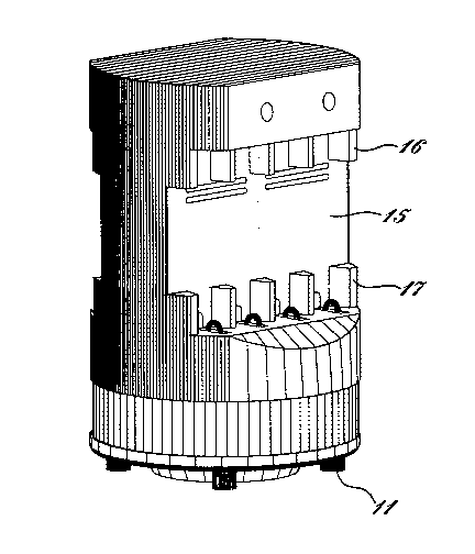
Battery charger for cylindrical cells which comprises a
substantially cylindrical housing with respective bottom and
upper parts separated by a pair of opposing recesses. In
operation the housing is arranged in upright position and
the recesses have planar rear faces extending in parallel
with each other and with the axis of symmetry of the hous-
ing. Spaced guiding ribs are provided at upper and lower end
zones of the faces to laterally guide the cells to be in-
serted. Contact members are arranged at upper and lower end
walls of the recesses between the ribs to spring-bias the
cells inserted. The bottom part is capable of locating a
mains transformer. Slots are defined in lower and upper
parts of the housing which define an airflow cooling
channel.

Revendications

Note : Les revendications sont présentées dans la langue officielle dans laquelle elles ont été soumises.


-5-
Claims:
1. Battery charger, comprising a substantially cylind-
rical housing having respective bottom and upper parts sepa-
rated by a pair of opposing recesses, in operation said
housing is arranged in upright position, said recesses have
planar rear faces extending in parallel with each other and
with axis of symmetry of said housing, spaced guiding ribs
are provided at upper and lower end zones of said faces to
laterally guide cells to be inserted, contact members being
arranged at upper and lower end walls of the recesses bet-
ween said ribs to spring bias the cells inserted, said bot-
tom part is capable of locating a mains transformer, slots
are defined in said housing to define an airflow cooling
channel.
2. The battery charger as claimed in claim 1, wherein
said slots are provided at upper zone of said rear planar
surfaces of said recesses and at bottom surface of said bot-
tom part, said bottom part comprising short legs keeping a
distance between said slots at the bottom surface and any
support surface on which said battery charger is standing.
3. The battery charger as claimed in claim 1, wherein
said upper part has a pair of parallel planar faces above
said recesses and at least one of said planar faces comprise
display means indicating charge state of cells charged.
4. The battery charger as claimed in claim 1, wherein
one of said recesses serving as holder of cells that cannot
be charged when being inserted in the holder recess.
5. The battery charger as claimed in claim 1, wherein at
one end wall of said recess spring guiding slots are provid-
ed between said ribs, and arched biasing springs that serve
as contact members are lead through the guiding slots.

-6-
6. The battery charger as claimed in claim 1, wherein
said bottom part is formed to locate a toroidal transformer.

Description

Note : Les descriptions sont présentées dans la langue officielle dans laquelle elles ont été soumises.


2128~53
Battery charger for cylindrical batteries
The present utility model relates to a battery charger
of the household type with built in mains transformer and
cord with a plug in connector which is capable of holding
and receiving a plurality of cylindrical batteries mainly of
the "AA" and "AAA", "C" and "D" types.
With increasing number of household electric and elect-
ronic appliances more and more battery cells are used. Re-
chargeable cells are often preferred to primary cells, since
they can be used through a large number of cycles, and they
are therefore substantially cheaper compared to the use of a
corresponding number of primary cells and constitute smaller
load to the environment as well. In a household where a plu-
rality of rechargeable cells is used, a battery charger is
also required.
Battery chargers are generally arranged in a plastic
housing provided with a compartment for the cells to be
charged, and the electrical components of the charger comp-
rise a mains transformer, a rectifier, one or more charging
circuits and preferably display means e.g. light emitting
diodes (LEDs) which give optical information on the status
of the charging process. Smaller battery chargers can be
plugged in the mains receptacle, while larger ones consti-
tute self supporting units connected to the line voltage by
means of a cord.
During the operation of the charger heat is generated,
and the design of the charger should provide appropriate
cooling so that the temperature of the electrical components
and of the cells must remain within acceptable limits.
Further requirements imposed on a battery charger are easy
handling, mechanical stability and pleasing appearance.
The primary object of the present utility model is to
provide a battery charger which can well meet all these re-
quirements.
This objective has been achieved by providing a battery

2128853
charger that comprises a substantially cylindrical housing
with respective bottom and upper parts separated by a pair
of opposing recesses. In operation the housing is arranged
in upright position, the recesses have planar rear faces
which extend in parallel with each other and with the axis
of symmetry of the housing. Spaced guiding ribs are provided
at upper and lower end zones of the faces to laterally guide
cells to be inserted, furthermore contact members are ar-
ranged at upper and lower end walls of the recesses between
the ribs to spring-bias the cells inserted. The bottom part
is capable of locating a mains transformer and slots are de-
fined in the housing to define an airflow cooling channel.
In a preferable embodiment the slots are provided at the
upper zone of the rear planar surfaces of the recesses and
at the bottom surface of the bottom part which comprises
short legs for keeping a distance between the slots at the
bottom surface and any support surface on which the battery
charger is standing.
It is preferable if the upper part has a pair of paral-
lel planar faces above the recesses and at least one of the
planar faces comprise display means indicating charge state
of cells charged.
The available space can be utilized in such a way that
one of the recesses serves as holder of cells only, i.e.
these cells cannot be charged but only stored.
In a still preferable embodiment at one end wall of the
recess spring-guiding slots are provided between the ribs,
and arched biasing springs that serve as contact members are
lead through the associated guiding slots.
It is preferable from the point of view of utilizing
available space and increasing stability if the bottom part
of the housing is formed to locate a toroidal transformer.
The battery charger will now be described in connection
with a preferable embodiment, in which reference will be
made to the accompanying drawings. In the drawing:

212X853
FIG. 1 is the perspective view of the battery charger;
FIG. 2 shows the battery charger in side view;
FIG. 3 shows the battery charger in elevation view; and
FIG. 4 shows the battery charger in top view.
The battery charger 10 has a substantially cylindrical
housing which stands in upright position on four short legs
11. Respective recesses 12, 13 are formed at two opposing
sides of the housing which have profiles best shown in FIG.
2. Each recess has a planar rear surface 14, 15. Short sepa-
ration ribs 16, 17 project from upper and lower end zones of
the planar surfaces spaced to guide insertion of cylindrical
AA size cells. Four cells can be inserted at each side of
the housing. The separation ribs 16, 17 have wedge-shaped
lateral surfaces narrowing in forward direction, and the
outer surfaces of the outermost ribs are constituted by the
cylindrical surface of the housing. The recesses 12, 13 have
narrow horizontal upper and lower walls 18, 19. The lower
walls 19 have small slots at locations that correspond to
the middle zones of the spacings defined between the ribs 17
and arched contact springs 20 extend through each slot. Flat
contact members 21 with slightly projecting spherical tips
are mounted on the upper walls 18 between the upper ribs 16.
The contact members 21 are arranged in respective recesses
which are only slightly wider than the tip representing the
positive pole of a cell, whereby there will be no contact
when a cell is inserted with incorrect polarity.
If a cell is inserted in a slot with correct polarity,
the two end contacts thereof will be spring biased between
the upper contact member 21 and the lower contact spring 20,
and the biasing force is provided by the fact that the cell
pushes the contact spring 20 in downward direction. The four
ribs ensures lateral support for the inserted cell.
Horizontal cooling slots 22 are provided at the upper
zones of the planar surfaces 12, 13 which together with
slots at the bottom of the housing (not shown in the draw-
ing) form inlets and outlets of an airflow cooling channel

2 i28853
defined in the housing. The legs 11 provide a spacing
between the slots at the bottom part and any support surface
on which the battery charger is standing, so that air can
freely flow therethrough.
The battery charger is capable of receiving and charging
eight AA cells. In embodiments designed for charging four
cells only, the recess for the other four cells can well be
used to store already charged cells. The recesses designed
for cell storage only are not provided with upper contacts
21 and the contact springs 21 serve as biasing members.
The housing has respective rectangular planar faces 23,
24 above the recesses 12, 13 in which, at the charger side,
light emitting diodes (LEDs) 25, 26 can be arranged which
indicate the charging state of the cells inserted. When the
left LED 25 lights, the charging process goes on, and when
the right LED 26 lights, the cells are fully charged.
The housing comprises respective inclined planar sur-
faces 27, 28 starting at the outer edges of the horizontal
walls 19, 20 which has no other specific function than of-
fering a more pleasing appearance.
The wide circular bottom portion of the housing spaced
from the support surface by the legs 11 locates the heaviest
and largest component of the battery charger, the mains
transformer, and such a form facilitates the use of a toro-
idal transformer. The transformer arranged in the lower part
of the housing increases mechanical stability and it is
thereby far away from other electronic components which can
well be located in the head portion above the recesses. The
heat and magnetic field of the transformer is well separated
from any sensitive component.
The housing offers several places for the arrangement of
labels and inscriptions. Favorable locations for this pur-
pose are the mantle surface 29 of the lower part of the
housing, the two planar faces 23, 24, the top surface 30 and
for warnings and other messages the planar rear surfaces 14,
15 of the recesses which will be visible when no cell is in-
serted.

Dessin représentatif
Une figure unique qui représente un dessin illustrant l'invention.
États administratifs

2024-08-01 : Dans le cadre de la transition vers les Brevets de nouvelle génération (BNG), la base de données sur les brevets canadiens (BDBC) contient désormais un Historique d'événement plus détaillé, qui reproduit le Journal des événements de notre nouvelle solution interne.

Veuillez noter que les événements débutant par « Inactive : » se réfèrent à des événements qui ne sont plus utilisés dans notre nouvelle solution interne.

Pour une meilleure compréhension de l'état de la demande ou brevet qui figure sur cette page, la rubrique Mise en garde , et les descriptions de Brevet , Historique d'événement , Taxes périodiques et Historique des paiements devraient être consultées.

Historique d'événement

Description Date
Inactive : CIB de MCD 2006-03-11
Le délai pour l'annulation est expiré 2000-07-26
Demande non rétablie avant l'échéance 2000-07-26
Réputée abandonnée - omission de répondre à un avis sur les taxes pour le maintien en état 1999-07-26
Demande publiée (accessible au public) 1995-08-05

Historique d'abandonnement

Date d'abandonnement Raison Date de rétablissement
1999-07-26

Taxes périodiques

Le dernier paiement a été reçu le 1998-07-07

Avis : Si le paiement en totalité n'a pas été reçu au plus tard à la date indiquée, une taxe supplémentaire peut être imposée, soit une des taxes suivantes :

  • taxe de rétablissement ;
  • taxe pour paiement en souffrance ; ou
  • taxe additionnelle pour le renversement d'une péremption réputée.

Les taxes sur les brevets sont ajustées au 1er janvier de chaque année. Les montants ci-dessus sont les montants actuels s'ils sont reçus au plus tard le 31 décembre de l'année en cours.
Veuillez vous référer à la page web des taxes sur les brevets de l'OPIC pour voir tous les montants actuels des taxes.

Historique des taxes

Type de taxes Anniversaire Échéance Date payée
TM (demande, 3e anniv.) - petite 03 1997-07-28 1997-07-25
TM (demande, 4e anniv.) - petite 04 1998-07-27 1998-07-07
Titulaires au dossier

Les titulaires actuels et antérieures au dossier sont affichés en ordre alphabétique.

Titulaires actuels au dossier
PURE ENERGY BATTERY CORPORATION
Titulaires antérieures au dossier
ROBERT FLACK
Les propriétaires antérieurs qui ne figurent pas dans la liste des « Propriétaires au dossier » apparaîtront dans d'autres documents au dossier.
Documents

Pour visionner les fichiers sélectionnés, entrer le code reCAPTCHA :


Pour visualiser une image, cliquer sur un lien dans la colonne description du document. Pour télécharger l'image (les images), cliquer l'une ou plusieurs cases à cocher dans la première colonne et ensuite cliquer sur le bouton "Télécharger sélection en format PDF (archive Zip)" ou le bouton "Télécharger sélection (en un fichier PDF fusionné)".

Liste des documents de brevet publiés et non publiés sur la BDBC .

Si vous avez des difficultés à accéder au contenu, veuillez communiquer avec le Centre de services à la clientèle au 1-866-997-1936, ou envoyer un courriel au Centre de service à la clientèle de l'OPIC.


Description du
Document 
Date
(aaaa-mm-jj) 
Nombre de pages   Taille de l'image (Ko) 
Abrégé 1995-08-04 1 22
Description 1995-08-04 4 210
Revendications 1995-08-04 2 50
Dessins 1995-08-04 2 49
Dessin représentatif 1999-10-21 1 30
Courtoisie - Lettre d'abandon (taxe de maintien en état) 1999-08-22 1 187
Taxes 1998-07-06 1 49
Taxes 1997-07-24 1 50
Taxes 1996-07-24 1 48