Sélection de la langue

Search

Sommaire du brevet 2134893 

Énoncé de désistement de responsabilité concernant l'information provenant de tiers

Une partie des informations de ce site Web a été fournie par des sources externes. Le gouvernement du Canada n'assume aucune responsabilité concernant la précision, l'actualité ou la fiabilité des informations fournies par les sources externes. Les utilisateurs qui désirent employer cette information devraient consulter directement la source des informations. Le contenu fourni par les sources externes n'est pas assujetti aux exigences sur les langues officielles, la protection des renseignements personnels et l'accessibilité.

Disponibilité de l'Abrégé et des Revendications

L'apparition de différences dans le texte et l'image des Revendications et de l'Abrégé dépend du moment auquel le document est publié. Les textes des Revendications et de l'Abrégé sont affichés :

  • lorsque la demande peut être examinée par le public;
  • lorsque le brevet est émis (délivrance).
(12) Brevet: (11) CA 2134893
(54) Titre français: METHODE ET CHAMBRE DE COMBUSTION POUR LA COMBUSTION D'UN PREMELANGE DE GAZ
(54) Titre anglais: METHOD AND COMBUSTOR FOR THE COMBUSTION OF A PREMIXED GAS
Statut: Périmé et au-delà du délai pour l’annulation
Données bibliographiques
(51) Classification internationale des brevets (CIB):
  • F23D 14/02 (2006.01)
  • F23D 14/66 (2006.01)
  • F23L 07/00 (2006.01)
  • F23R 03/10 (2006.01)
  • F23R 03/28 (2006.01)
(72) Inventeurs :
  • MANDAI, SHIGEMI (Japon)
  • TANAKA, KATSUNORI (Japon)
  • SATO, NOBUO (Japon)
  • TANIMURA, SATOSHI (Japon)
(73) Titulaires :
  • MITSUBISHI JUKOGYO KABUSHIKI KAISHA
(71) Demandeurs :
  • MITSUBISHI JUKOGYO KABUSHIKI KAISHA (Japon)
(74) Agent: GOWLING WLG (CANADA) LLP
(74) Co-agent:
(45) Délivré: 1999-09-07
(86) Date de dépôt PCT: 1994-03-08
(87) Mise à la disponibilité du public: 1994-09-15
Requête d'examen: 1994-11-01
Licence disponible: S.O.
Cédé au domaine public: S.O.
(25) Langue des documents déposés: Anglais

Traité de coopération en matière de brevets (PCT): Oui
(86) Numéro de la demande PCT: PCT/JP1994/000363
(87) Numéro de publication internationale PCT: JP1994000363
(85) Entrée nationale: 1994-11-01

(30) Données de priorité de la demande:
Numéro de la demande Pays / territoire Date
72948/1993 (Japon) 1993-03-08

Abrégés

Abrégé anglais


An object of the present invention is to overcome the
disadvantages of a conventional combustor having a fuel-air
premixing nozzle wherein variation in combustion rate
resulting from variation in the fuel concentration of the
premixed gas cause variation in flame length and may
eventually lead to the development of combustive vibration.
This invention provides a combustion method and combustor
which is characterized in that a fluid (8) containing no
fuel is fed between a premixed gas layer (2) formed by
injecting a premixed gas through a premixing nozzle (1) and
a hot gas layer (5) formed from a portion of the hot gas
resulting from the combustion of the premixed gas, the hot
gas layer (5) circulating or staying in a region downstream
of the outlet of the premixing nozzle (1).

Revendications

Note : Les revendications sont présentées dans la langue officielle dans laquelle elles ont été soumises.


THE EMBODIMENT OF THE INVENTION IN WHICH AN EXCLUSIVE PROPERTY
OR PRIVILEGE IS CLAIMED ARE DEFINED AS FOLLOWS:
1. A combustor, comprising:
a pilot nozzle arranged in the centre of said combustor and having the
discharge end at a predetermined axial distance for injecting pilot fuel in a
direction
away from the longitudinal axis of said combustor and for generating a first
layer of
hot gas;
an intermediate nozzle arranged around said pilot nozzle and having the
discharge end at same said axial distance for feeding a neutral fluid in said
direction
away from said longitudinal axis and for forming a mid-temperature second
layer
around said first layer; and
a premixing nozzle arranged around said intermediate nozzle and having the
discharge end at same said axial distance for injecting premixed gas in a
direction
parallel to said longitudinal axis and for forming a third layer of premixed
gas around
said second layer, the combustion of said premixed gas being controlled in a
downstream region by the temperature of said second layer.
2. The combustor of claim 1, further comprising a tip at said discharge end of
said pilot nozzle for directing said neutral fluid between said third layer
and said first
layer.
3. A combustion method for burning premixed gas in a combustor, comprising
the steps of:
forming a central layer of hot gas by injecting fuel in a direction away from
the
longitudinal axis of said combustor;
injecting premixed gas in a direction parallel to the longitudinal axis of
said
combustor for forming an exterior layer that is coaxial and about said central
layer;
and
feeding a neutral fluid between said central and said exterior layers in said
direction away from the longitudinal axis of said combustor for forming a
mid-temperature layer between said central and said exterior layers, the
combustion of

said premixed gas being controlled in a downstream region by the temperature
of
said mid-temperature layer.

Description

Note : Les descriptions sont présentées dans la langue officielle dans laquelle elles ont été soumises.

X134893
DESCRIPTION
Title of the Invention
METHOD AND COMBUSTOR FOR THE COMBUSTION OF A PREMIXED GAS
Technical Field
This invention relates to a method for the combustion
of a premixed gas in a combustor having a fuel-air premix-
ing nozzle and useful for effecting low-NOX combustion and
a combustor therefor. This invention can be applied to
such combustors as gas turbine combustors, boilers, and
furnaces for use in chemical industry.
Background Art
Recently, in order to reduce the NOx content of
exhaust gas from gas turbine combustors and the like, there
is commonly employed a combustion method in which fuel is
premixed with combustion air and the resulting premixed gas
is burned under lean combustion conditions. This method
for the combustion of a premixed gas can eliminate areas
having uneven fuel concentrations and also local areas
burning at higher temperatures, resulting in a marked
reduction in the amount of NOx produced.
FIG. 3 illustrates a part of a burner based on the
conventional method for the combustion of a premixed gas.
In this figure, reference numeral 1 designates a premixing
nozzle, 2 designates a premixed gas, 3 designates a flame
holder, 4 designates a flame, 5 designates a circulating or
- 1 -

2134893
staying hot gas, 6 designates a pilot nozzle, and 7 desig-
nates a pilot fuel.
The premixed gas 2 injected through the premixing
nozzle 1 into the combustion chamber burns so as to go
round the flame holder 3, thus forming downstream a circu-
lating hot gas 5 serving for flame holding.
In this method for the combustion of a premixed gas,
the combustion rate of the premixed gas (i.e., the velocity
at which the flame advances into the unburned mixture)
becomes higher as the temperature of the premixed gas is
elevated and as the fuel concentration of the premixed gas
is increased. In particular, the fuel concentration may
cause marked variation in the resulting combustion rate.
Such variation in combustion rate causes variation in flame
length and may eventually lead to the development of com-
bustive vibration.
Disclosure of the Invention
The present invention has been made for the purpose
of solving the above-described problem and has for its
object the provision of a method and combustor for the
combustion of a premixed gas which can minimize the devel-
opment of combustive vibration due to variation in the fuel
concentration of the premixed gas.
In order to accomplish the above-described object,
the present invention provides:
- 2 -

2 1348 ~ 3
A combustor, comprising: a pilot nozzle; a fuel-air premixing nozzle for
inj ecting a premixed fuel-air gas and forming a premixed fuel-air gas layer
around and
coaxially said pilot nozzle; a passage for feeding a neutral fluid containing
no fuel,
said passage disposed between said pilot nozzle and said fuel-air premixing
nozzle;
and a tip on the discharge end of said pilot nozzle for directing said neutral
fluid
between said premixed fuel-air gas layer and a hot gas layer formed by the
combustion of said premixed fuel-air gas, said hot gas layer circulating or
staying in a
downstream the outlet of said premixing nozzle.
A combustion method for burning premixed gas in a combustor, comprising
the steps of: forming a first layer of hot gas in a central region of said
combustor;
injecting a premixed gas in a second layer that is coaxial and about said
first layer;
and feeding a neutral fluid between said first and second layers, for forming
a third
mid-temperature layer in between said premixed gas and said hot gas.
By the above-described means, a neutral fluid is fed
between the premixed gas layer and the hot gas, so that a
flame is not propagated directly from the hot gas to the
premixed gas. Instead, a mid-temperature gas is generated
by the mixing and diffusion of the hot gas and the neutral
fluid. Thereafter, the premixed gas is burned as a result
of the mixing and diffusion of the mid-temperature gas and
the premixed gas.
The mechanism by which the premixed gas is burned is
such that the hot gas and the premixed gas intermingle with
each other, during this process the premixed gas is heated
- 3 -
Ci..

X134893
by the heat transferred from the hot gas, and combustion is
initiated when the combustion starting temperature is
reached.
Thus, according to the present invention, the pre-
mixed gas is burned under mixing and diffusion rate con-
trol, as contrasted with an ordinary premixed flame in
which combustion is effected by flame propagation. Conse-
quently, it is possible to achieve combustion which is
little affected by the fuel concentration of the premixed
gas. As used herein, "diffusion" means that the hot gas
and the premixed gas intermingle with each other, and "rate
control" means the controlling of the rate of such diffu-
sion. "Diffusion rate control" means the controlling of
the rate at which the hot gas and the premixed gas inter-
mingle with each other.
Moreover, since the hot gas and the neutral fluid are
mixed to generate a mid-temperature gas which is then mixed
with the premixed gas, the flame temperature in this mixing
region is low and the production of NOx in this region is
minimized.
Furthermore, since the premixed gas is burned under
diffusion rate control, the main flame is long, and heat
generation or heat generation quotient can be spread in
space, so that combustive vibration can be prevented. The
reason why combustive vibration can be prevented is that
- 4 -

2134893
the combustion pressure is reduced by dispersion of the
heat generation and, moreover, the variation of flame
length relative to the total flame length becomes smaller
as a result of the prolongation of the flame.
As used herein, "heat generation quotient" means the
per area combustion (dQ/dx) of fuel (Q) with respect to the
axial distance (x) of a combustor.
Hrief Description of the Drawings
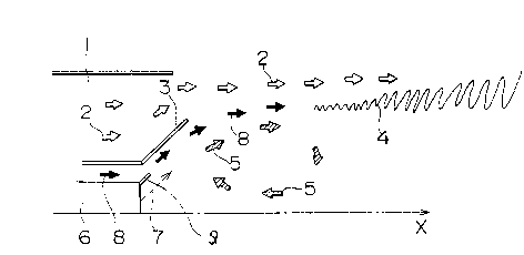
FIG. 1 is a schematic diagram illustrating an exem-
plary burner to which the present invention has been ap-
plied;
FIG. 2 is a graphical representation of experimental
data showing the effects of the present invention; and
FIG. 3 is a schematic diagram illustrating a burner
based on the conventional method for the combustion of a
premixed gas.
Best Mode for Carrying Out the Invention
FIG. 1 illustrates an exemplary burner for carrying
out the method of the present invention. In this figure,
the same elements as shown in FIG. 3 are designated by the
same reference numerals and no detailed explanation thereof
is given.
Referring to FIG. 1, a passage for feeding a neutral
fluid 8 is formed between a premixing nozzle 1 and a pilot
nozzle 6. The orifice for injecting the neutral fluid 8
- 5 -

213489 3
into the combustion chamber is configured so as to cause
the neutral fluid 8 to'flow out along the inner wall sur-
face of a flame holder 3 and the outer wall surface of a tip 9 defined at the
discharge
end of the pilot nozzle 6. The neutral fluid 8 is a fluid containing no fuel
and may
comprise, for example, air, exhaust gas, steam or the like.
In the arrangement of FIG. 1, a neutral fluid is fed
between a layer of a premixed gas 2 injected through the
premixing nozzle 1 and a circulating hot gas 5, so that the
premixed gas 2 injected through the premixing nozzle 1 does
not come into direct contact with the hot gas 5. The
neutral fluid 8 is first mixed with the hot gas 5 to gener-
ate a mid-temperature gas. Then, in a downward region,
this mid-temperature gas is mixed with the premixed gas 2
to form a flame 4.
Thus, since the hot gas 5 does not come into direct
contact with the premixed gas 2 fed through the premixing
nozzle 1, it is unlikely that a flame is propagated direct-
ly from the hot gas 5 to the premixed gas 2 and ignites the
premixed gas forcibly before the premixed gas diffuses
sufficiently, as is the case with conventional burners.
That is, the premixed gas 2 separated from the hot gas 5 by
the neutral fluid 8 can be burned under diffusion rate
control, so that a long main flame results. This means
that the heat generation quotient can be spatially spread
and small to prevent combustive vibration.
- 6 -

2134893
FIG. 2 is a graph showing the states of combustive
vibration when combustion was effected in a burner using
air as the neutral fluid 8 according to the method of the
present invention and in a conventional burner. In this
graph, the ordinate shows the internal pressure fluctuation
of the combustor which serves as a measure of combustive
vibration, and the abscissa shows the proportion of the
pilot fuel (i.e., the pilot fuel 7 for the formation of a
diffusion flame) to the total fuel (i.e., the main fuel
plus the pilot fuel). FIG. 2 indicates that, regardless of
the proportion of the pilot fuel, the internal pressure
fluctuation ratio is lower in the presence of a neutral
fluid (the present invention) than in the absence of a
neutral fluid (the~prior art). That is, FIG. 2 indicates
less combustive vibration in the presence of a neutral
fluid, demonstrating the effects of the present invention.
The present invention is not limited to the burner
design illustrated in FIG. 1, but comprehends all
combustors involving the formation of a circulating flow
wherein a neutral fluid is fed between the circulating flow
and the premixed gas. For example, the present invention
can be applied to combustors having various flame-holding
plates and combustors forming a circulating flow or a
stagnation point in a region having an abruptly expanded
flow path.

Dessin représentatif
Une figure unique qui représente un dessin illustrant l'invention.
États administratifs

2024-08-01 : Dans le cadre de la transition vers les Brevets de nouvelle génération (BNG), la base de données sur les brevets canadiens (BDBC) contient désormais un Historique d'événement plus détaillé, qui reproduit le Journal des événements de notre nouvelle solution interne.

Veuillez noter que les événements débutant par « Inactive : » se réfèrent à des événements qui ne sont plus utilisés dans notre nouvelle solution interne.

Pour une meilleure compréhension de l'état de la demande ou brevet qui figure sur cette page, la rubrique Mise en garde , et les descriptions de Brevet , Historique d'événement , Taxes périodiques et Historique des paiements devraient être consultées.

Historique d'événement

Description Date
Inactive : CIB de MCD 2006-03-11
Le délai pour l'annulation est expiré 2004-03-08
Lettre envoyée 2003-03-10
Accordé par délivrance 1999-09-07
Inactive : Page couverture publiée 1999-09-06
Inactive : Taxe finale reçue 1999-06-02
Préoctroi 1999-06-02
Un avis d'acceptation est envoyé 1999-03-22
Lettre envoyée 1999-03-22
Un avis d'acceptation est envoyé 1999-03-22
Inactive : Renseign. sur l'état - Complets dès date d'ent. journ. 1999-03-16
Inactive : Dem. traitée sur TS dès date d'ent. journal 1999-03-16
Inactive : Approuvée aux fins d'acceptation (AFA) 1999-02-19
Toutes les exigences pour l'examen - jugée conforme 1994-11-01
Exigences pour une requête d'examen - jugée conforme 1994-11-01
Demande publiée (accessible au public) 1994-09-15

Historique d'abandonnement

Il n'y a pas d'historique d'abandonnement

Taxes périodiques

Le dernier paiement a été reçu le 1999-02-03

Avis : Si le paiement en totalité n'a pas été reçu au plus tard à la date indiquée, une taxe supplémentaire peut être imposée, soit une des taxes suivantes :

  • taxe de rétablissement ;
  • taxe pour paiement en souffrance ; ou
  • taxe additionnelle pour le renversement d'une péremption réputée.

Les taxes sur les brevets sont ajustées au 1er janvier de chaque année. Les montants ci-dessus sont les montants actuels s'ils sont reçus au plus tard le 31 décembre de l'année en cours.
Veuillez vous référer à la page web des taxes sur les brevets de l'OPIC pour voir tous les montants actuels des taxes.

Historique des taxes

Type de taxes Anniversaire Échéance Date payée
TM (demande, 4e anniv.) - générale 04 1998-03-09 1998-01-27
TM (demande, 5e anniv.) - générale 05 1999-03-08 1999-02-03
Taxe finale - générale 1999-06-02
TM (brevet, 6e anniv.) - générale 2000-03-08 2000-02-07
TM (brevet, 7e anniv.) - générale 2001-03-08 2001-02-19
TM (brevet, 8e anniv.) - générale 2002-03-08 2002-02-18
Titulaires au dossier

Les titulaires actuels et antérieures au dossier sont affichés en ordre alphabétique.

Titulaires actuels au dossier
MITSUBISHI JUKOGYO KABUSHIKI KAISHA
Titulaires antérieures au dossier
KATSUNORI TANAKA
NOBUO SATO
SATOSHI TANIMURA
SHIGEMI MANDAI
Les propriétaires antérieurs qui ne figurent pas dans la liste des « Propriétaires au dossier » apparaîtront dans d'autres documents au dossier.
Documents

Pour visionner les fichiers sélectionnés, entrer le code reCAPTCHA :


Pour visualiser une image, cliquer sur un lien dans la colonne description du document. Pour télécharger l'image (les images), cliquer l'une ou plusieurs cases à cocher dans la première colonne et ensuite cliquer sur le bouton "Télécharger sélection en format PDF (archive Zip)" ou le bouton "Télécharger sélection (en un fichier PDF fusionné)".

Liste des documents de brevet publiés et non publiés sur la BDBC .

Si vous avez des difficultés à accéder au contenu, veuillez communiquer avec le Centre de services à la clientèle au 1-866-997-1936, ou envoyer un courriel au Centre de service à la clientèle de l'OPIC.


Description du
Document 
Date
(aaaa-mm-jj) 
Nombre de pages   Taille de l'image (Ko) 
Abrégé 1995-10-27 1 22
Revendications 1995-10-27 1 22
Dessins 1995-10-27 3 42
Description 1995-10-27 7 227
Description 1999-02-02 7 261
Revendications 1999-02-02 2 49
Dessins 1999-02-02 3 28
Dessin représentatif 1999-05-16 1 6
Dessin représentatif 1999-08-31 1 6
Avis du commissaire - Demande jugée acceptable 1999-03-21 1 164
Avis concernant la taxe de maintien 2003-04-06 1 174
Correspondance 1999-06-01 1 29
Taxes 2000-02-06 1 29
Taxes 1998-01-26 1 28
Taxes 1999-02-02 1 33
Taxes 1997-02-03 1 31
Taxes 1995-12-27 1 29
Correspondance de la poursuite 1994-10-31 11 272
Rapport d'examen préliminaire international 1994-10-31 14 432
Correspondance reliée au PCT 1995-02-14 2 62
Correspondance de la poursuite 1998-12-01 2 64
Correspondance de la poursuite 1998-10-08 2 78
Correspondance de la poursuite 1998-03-05 3 122
Demande de l'examinateur 1998-04-08 2 47
Demande de l'examinateur 1997-09-15 2 46
Correspondance de la poursuite 1997-08-26 1 33
Demande de l'examinateur 1997-05-22 1 62
Correspondance de la poursuite 1997-05-06 2 90
Correspondance de la poursuite 1997-05-06 2 96
Demande de l'examinateur 1996-11-25 2 61
Demande d'entrée en phase nationale 1994-10-31 6 265