Note : Les descriptions sont présentées dans la langue officielle dans laquelle elles ont été soumises.
_ 2137886
r ~ t
A DOUBLE-HEADED TOOTHBRUSH
TECHNICAL FIELD
The invention relates generally to toothbrushes, and more
particularly to a novel construction of a toothbrush with
05 one brushhead on either end of an element, half of the
element being slidably concealed in a pear-shaped recepta-
cle cover.
BACKGROUND ART
Toothbrushes for cleaning teeth, with the bristle-carrying
brushhead aligned with the handle, are commonly known
objects. Though it is universally recognised that the most
efficient way to clean the teeth is to move the brush up
and down, presently available toothbrushes from the market
do not facilitate this movement, the axis of the brushhead
being in line with the axis of the handle.
US Patent No. 611788 of October 4 1898 by Isaac N Lincoln
disclosed a folding toothbrush, with a jointed handle, one
part provided with bristles, and the other part consisting
of a receptacle for tooth powder, a series of perforations
extending longitudinally from either end of the receptacle.
US Patent No. 4033007 and 4370773 respectively dated July 5
1979 and February 1 1983 by Joseph Hadery disclosed a
toothbrush with an upright, self support handle having a
213`7886
diametrically enlarged hollow base of a size to receive and
store a brushhead therein.
Australian Patent No. AU-A-58049/86 by Raymond Ernest and
Stephen J Ginsberg dated December 3, 1987 disclosed a modu-
05 lar oral hygiene system with a handle comprising generallyparallel front and rear portions connected by a middle
portion which forms an angle of about 30 to about 50
degrees with said front and rear portions.
US Patent No. 5165135 and UK Patent No. 2224928 dated
respectively November 24 1992 and April 8 1992 by Chan
Boon Su disclosed a toothbrush comprising essentially: an
elongate handle, an elongate bristle-carrying head on the
distal end of the said handle, a suitable means of turning
the brushing head about an axis parallel to the longitudi-
nal axis of the brushing head, and the longitudinal axis ofthe head forming an angle to the longitudinal axis of said
handle.
The subject of this disclosure is a toothbrush having one
brushhead attached to either end of an elongate element,
with each half of the element further comprising an outer
portion and a holder portion integrally connected by a
middle portion shaped like a goose-neck.
2137886
The longitudinal axis of the bristle~carrying brushhead is
disposed at an angle to the longitudinal axis of the
adjacent outer section of the element; and the plane con-
taining the longitudinal axis of the outer section of the
05 element is disposed at an angle to the plane containing the
longitudinal axis of the holder section of the element.
The first half of the element with an attached brushhead
turned in one direction is the mirror-image of the second
half with an attached brushhead turned in the opposite
direction, and the element substantially assumes an extend-
ed "M" shape.
SUMMARY OF THE INV~N~l~lON
It is an object of the invention to encourage brushing the
teeth in an up and down manner.
It is another object of the invention to provide a tooth-
brush capable of efficiently brushing the buccal and
lingual surfaces of the teeth.
It is another object of the invention to provide a tooth-
brush that is easy and economical to manufacture and that
lends itself to mass production.
It is yet another object of the invention to avoid turning
the brushhead.
21378~6
These objects are achieved by three working models dis-
closed in the following description. To those skilled in
the art, other models and modifications are possible fol-
lowing the disclosure of this invention. In one preferred
OS model, a bristle-carrying brushhead is attached at either
end of an elongate element, half of the element with the
brushhead being slidably concealed within a cavity formed
therein a receptacle cover which pivotally supports said
element at its centre. The longitudinal axis of the
bristle-carrying brushhead is disposed at an angle to the
longitudinal axis of the adjacent portion of the element.
In another model, the elongate element with two bristle-
carrying brushheads is used directly without the receptacle
cover.
Yet another model comprises separately one half of the
element with its brushhead turned in one direction, and the
other half of the element with its brushhead turned in the
opposite direction.
SPECIFIC EXAMPLE
The foregoing and other objects and advantages will be
apparent from the description below of the two models: one
provided with a receptacle cover and the other without.
2137886
The characteristics and the purposes will be clearly seen
in the accompanying drawings.
Figure (la) shows the front view of a toothbrush made
according to the invention comprising an elongate element
05 (lO) carrying a bristle-carrying brushhead at either end.
Figure (lb) shows the back view of the element as shown in
Figure (la).
Figure (lc) shows a first side view of the element as shown
in Figure (la).
Figure (ld) shows a second side view of the element as
shown in Figure (la).
Figure (2a) shows the side cross section view of a first
asymmetrical half representing the front half of the recep-
tacle cover.
Figure (2b) shows the side cross section view of the second
asymmetrical half representing the back half of the recep-
tacle cover.
Figure (2c) shows the side view of a fully assembled recep-
tacle cover.
Figure (2d) shows the back view of the cover as shown in
Figure (2c).
2137886
-- 6 --
Figure (2e) shows the front view of the cover as shown in
Figure (2c).
Figure (3a) shows the front view of the preferred model
according to the invention, in first alternate position,
05 with half of the elongate element concealed in a receptacle
cover.
Figure (3b) shows the back view of the toothbrush as shown
in Figure (3a).
Figure (3c) shows a first side view of the toothbrush as
shown in Figure (3a).
Figure (3d) shows a second side view of the toothbrush as
shown in Figure (3a).
Figure (4a) shows the front view of the toothbrush accord-
ing to the invention, in second alternate position, with
the element rotated a full turn.
Figure (4b) shows the back view of the toothbrush as shown
in Figure (4a).
Figure (4c) shows a first side view of the toothbrush as
shown in Figure (4a).
ZO Figure (4d) shows a second side view of the toothbrush as
shown in Figure (4a).
2l3788e
-- 7
For the sake of convenience and clarity, common numerals
are used to refer to common parts or components described
in the invention. Where it is necessary to differentiate
them, a suffix "a" or "b" is added to the common numerals.
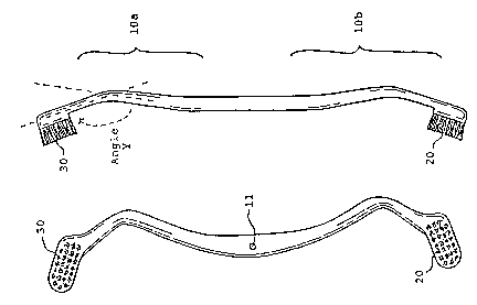
05 With reference to Figures (la), (lb), (lc), and (ld), the
element (10) in one model of the toothbrush according to
the invention is elongate. The element (10) comprises one
curved portion (lOa) integrally moulded with a second
mirror-image curved portion (lOb), so that the element (10)
looks similar to an extended "M" shape. Substantially at
the junction of the two portions (lOa, lOb), there is
provided a central hole (11) whereby a pivoting element
from a receptacle cover (not shown) is applied, when it is
desirable to cover half of the element (10). Otherwise, as
in another model, the central hole (11) is not provided and
the element (10) with double brushheads (20, 30) will be
used directly as a handle of the toothbrush.
The curved portion (lOa, lOb) of the element further com-
prises outer (14) and holder (12) sections connected inte-
grally with a middle section (13) which forms generally agoose-neck with said outer (14) and holder (12) sections.
The goose-neck middle section (13) allows for smooth brush-
ing unhampered by the confines of the mouth.
2137886
-- 8
The extreme end (151 of said outer (14) section is enlarged
and flattened. A bristle-carrying brushhead (20, 30) is
ultrasonically attached to this enlarged and flattened end
(15), such that a substantial section of the bristle-carry-
05 ing brushhead (20, 30) projects away from the adjacentouter section (14). It is therefore important for the
brushhead (20, 30) and the enlarged end (15) to be made of
the same plastic material.
The longitudinal axis of the enlarged end (15) and the
brushhead (20, 30) is preferably at an angle "x" to the
longitudinal axis of the adjacent outer section (14) of the
element (10). The angle "x" is preferably about 100 to 175
degrees from the longitudinal axis of the outer section
(14) of the element (10). The plane containing the longi-
tudinal axis of the enlarged end (15) and the brushhead(20, 30) is also disposed at a sloping angle "y" to the
plane containing the longitudinal axis of the holder sec-
tion (12) of the element (10). The angle "y" is preferably
about 100 to 175 degrees from the plane containing the
longitudinal axis of the holder section (12) of the element
(10) .
Now referring to Figures (2a), (2b), (2c), (2d), and (2e),
a receptacle cover (40) is formed from two asymmetrical
halves (41, 42) which is ultrasonically fused at its mating
213`7886
t
edges (46, 47). There is preferably provided a squarish
window (45) towards its base on the first half (41), to
expose the brushhead inside the receptacle cover (40) for
the convenience of applying tooth paste. The first half
05 (41) is conveniently described as the front half of the
cover. Towards the narrow end of the first front half (41),
there is integrally and inwardly provided a short protru-
sion which acts as a pivot element (43). There is no
window (45) on the second half (42). The second half (42)
can be conveniently described as the back half of the
cover. An opening (44) is provided at a corresponding
position towards the narrow end of the back half (42), in
order to receive the end of the pivot element (43).
When the element (10) is provided with the receptacle cover
(40) as shown in Figures (3a), (3b), (3c), (3d), (4a),
(4b), (4c) and (4d), this pivot element (43) connects, the
two halves of the cover (41, 42). One brushhead (20, 30)
is exposed while the other brushhead (30, 20) is slidably
concealed in the cavity (48) formed between the two asym-
metrical halves (41, 42) when they are fused together. Thefirst and second halves (41, 42) are preferably pear-
shaped. To allow for free rotation of the curved portions
(10) of the element in and out of the cover, the sides of
the cover (40) are advantageously open.