Note : Les descriptions sont présentées dans la langue officielle dans laquelle elles ont été soumises.
2I3S61'~
....
Case 1143
CYLINDRICAL ELECTROMECHANICAL TRANSDUCER
The present invention concerns electromechanical
transducers exhibiting a configuration of the cylindrical
type and being adapted in particular to serve as stepping
motors. Specifically, the present invention concerns
electromechanical transducers having a diameter on the
order of some centimeters.
BACKGROUND OF THE INVENTION
Such electromechanical transducers of small
dimensions and cylindrical configuration are utilised in
various applications and in particular in
telecommunication systems, in the audiovisual domain, in
the medical domain, in robotics or again in security
systems.
From patent document US 3 952 219 there is known a
motor of cylindrical configuration and including three
longitudinal stator pieces defining an arc of a circle
centered on the axis of rotation of the rotor. The three
stator pieces are maintained between two flanges, each
including a hole for the rotor shaft onto which is secured
the permanent. magnet. Three windings are mounted
respectively on first portions of the three stator pieces.
Other portions of such stator pieces are located facing
the permanent magnet of the rotor. The stator pieces are
radially positioned by the dog points provided at the ends
of the stator pieces, such dog points being introduced
into notches provided to this effect in the two flanges of
the motor.
Such motor, although of relatively easy assembly,
exhibits a certain number of problems. Initially, the
rotor shaft traverses the motor longitudinally which is
detrimental for the rotational stability of the rotor.
Additionally, to bring about a mechanical coupling with an
external arrangement, it is necessary to attach a gear
213861
,,", 2
onto the rotor shaft following assembly of the motor.
Next, the form of the pole pieces generates a relatively
substantial leakage flux and the permanent magnet of the
rotor is not magnetically positioned according to the
direction of the axis of rotation of such rotor. There is
thus no axial magnetic positioning of the rotor.
Thereafter, the two flanges serving to hold the stator
pieces are not united with one another. From this fact,
the structure of the motor is not stable, which spoils the
yield of such motor.
There is also known from patent document DE 1 613 302
a motor comprising a rotor with a permanent magnet
comprising a mounting formed from a central body, a flange
located at one end of the central body and an external
cylindrical portion rising up from the edge of the flange.
This motor includes three stator pieces, each bearing an
energization winding on a first portion and having a
second portion located facing the permanent magnet of the
rotor.
The motor further comprises a magnetic flux return
disc secured to the central body with the help of a
securing screw and a closing cover for the housing in
which the permanent magnet is located. Such permanent
magnet is mounted on a shaft, a first pivot of which is
arranged in a bearing provided in the above-mentioned
flange. Such shaft traverses the cover in order to permit
the transmission of a force moment. The flange is located
at the central body side relatively to the rotor permanent
magnet. Three openings are provided in such flange, such
openings being respectively traversed by the three stator
pieces.
The portion forming the polar expansion of each of
said stator pieces is further separated from the central
axis of the rotor than the portion on which the winding is
mounted. This configuration generates poor magnetic flux
coupling of the winding with the magnetic flux of the
permanent magnet. Once again, such motor exhibits poor
axial centering of the rotor, the latter being drawn in
2138617
3
the direction of the flange. In order to maintain the
rotor in a predetermined axial position, an abutment is
necessary at the end of the pivot engaged in the bearing
provided in the flange, which increases the friction on
the shaft of the rotor and consequently diminishes the
yield of the motor.
It will be noted that the windings are provided on a
first side of the flange while the polar expansions and
the permanent magnet of the rotor are arranged on the
other side of such flange. The stator pieces are radially
positioned with the help of openings provided in the
flange. However, such motor does not exhibit axial
positioning means of the stator pieces. In a particularly
disadvantageous manner, the windings are squeezed between
the magnetic flux return disc and the flange. The securing
of the magnetic flux return disc brings about a crushing
of the windings and a longitudinal displacement of the
stator pieces. Furthermore, the windings are brought in
once the stator pieces are arranged in the openings
provided in the flange. The construction of this motor is
thus of small reliability and its assembly is complicated.
Finally, it will be noted that in order to transmit a
force couple, it is necessary to mount a gear on the rotor
shaft once the cover is assembled on the stator pieces.
The purpose of the present invention is to overcome
the drawbacks described hereinabefore in furnishing a
reliable electromechanical transducer having a cylindrical
configuration adapted for small motors and capable of
being mass produced for a low manufacturing cost.
SUMMARY OF THE INVENTION
Consequently, the present invention has as object an
electromechanical transducer comprising a stator and a
rotor capable of turning around a rotation axis and
including a permanent magnet, said stator comprising
magnetic coupling means serving to couple magnetically at
2138617
"..." 4
least a first winding to the permanent magnet, said
magnetic coupling means comprising .
- a first polar expansion and a second polar
expansion each partially defining a stator hole traversed
by said rotor, such first and second polar expansions
being separated from one another by zones of high magnetic
reluctance,
- a first polar arm and a second polar arm each
having a first end and a second end, such first and second
polar arms having their said first ends magnetically
coupled respectively to said first polar expansion and to
said second polar expansion and having their second ends
magnetically coupled to one another, said first and second
polar arms being oriented in a direction substantially
parallel to said rotation axis, said first winding being
borne by the first polar arm. The stator furthermore
comprises a mounting including an elongated central body
having a longitudinal central axis substantially merged
with the rotation axis of the rotor and also including an
end flange integral with the central body substantially
perpendicular to the longitudinal central axis thereof.
The transducer according to the invention is characterized
in that the polar arms and the polar expansions are
located below the upper surface of the flange relative to
the central body, the polar expansions bearing axially
against a surface of such flange.
Thanks to the characteristics of the invention
mentioned hereinabove, the assembly of the
electromechanical transducer is easy and the various pole
portions can be solidly secured to the mounting so as to
be positioned axially and radially.
According to a specific characteristic of the
invention, the second ends of said polar arms are
magnetically coupled to respective magnetic contact lugs
belonging to the magnetic coupling means basically located
in a plane perpendicular to the rotation axis of the
rotor.
213861
In a specific embodiment, the magnetic contact lugs
are mechanically coupled among themselves by a ring of low
magnetic reluctance belonging to the magnetic coupling
means arranged to bear against such magnetic coupling
lugs. Additionally, each of the polar arms forms, together
with the respective polar expansion and the respective
magnetic contact lug, one and the same pole piece.
According to three principal embodiments of the
invention, there is respectively provided a three phase
transducer, a two phase transducer and a single phase
transducer.
Other characteristics and advantages of the invention
will be described hereinafter with the help of the
following description prepared with reference to the
attached drawings given by way of non-limiting examples.
BRIEF DESCRIPTION OF THE DRAWINGS
- Figure 1 is a side view of a three phase
electromechanical transducer according to the invention;
- figure 2 is a longitudinal cross section of the
electromechanical transducer shown on figure 1;
- figures 3 and 4 are cross sectional views of the
electromechanical transducer shown on figures 1 and 2
respectively according to the section lines III-III and
IV-IV;
- figure 5 shows the magnetic schematic of the
electromechanical transducer shown on figures 1 to 4;
- figure 6 is a side view of a two phase
electromechanical transducer according to the invention;
- figure 7 shows the magnetic schematic of the
electromechanical transducer shown on figure 6;
- figure 8 is a longitudinal cross section of a
single phase electromechanical transducer according to the
invention;
- figures 9 and 10 are cross section views of the
electromechanical transducer shown on figure 8
respectively according to the section lines IX-IX and X-X.
z~~~~~~
6
DESCRIPTION OF THE PREFERRED EMBODIMENTS
In referring hereinafter to figures 1 to 5, there
will be described a three phase electromechanical
transducer according to the invention.
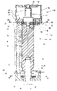
Such transducer comprises a stator 2 and a rotor 4
capable of turning around a rotation axis 6 determined
relative to stator 2.
Stator 2 includes three pole pieces 8, 10 and 12.
Each of the pole pieces 8, 10 and 12 comprises
respectively a polar arm 14, 16 and 18, a polar expansion
20, 22 and 24 and a magnetic contact lug 26, 28 and 30.
The polar expansions 20, 22 and 24 are separated from one
another by gaps 31 forming high magnetic reluctance zones
and are angularly shifted from one another through an
angle of 120°.
The polar arms 14, 16 and 18 bear respectively
energization windings 32, 34 and 36. Such polar arms 14,
16, and 18 are oriented in the direction of the rotation
axis 6 of rotor 4.
Rotor 4 includes a bipolar permanent magnet 38 having
radial magnetization and a gear 40 serving to couple
mechanically such rotor 4 to a mechanical wheel (not
shown) serving for the transmission of a force moment.
The three polar expansions 20, 22 and 24 extend in a
common plane 42 perpendicular to the rotation axis 6.
The stator 2 also includes a non-magnetic mounting 44
comprising an elongated central body 46 having a central
longitudinal axis 48 merged with the rotation axis 6 of
rotor 4. Mounting 44 further comprises a cage 50 formed by
a flange 52, a lateral wall 54 and a cover 56. Flange 52
and wall 54 are formed together with the elongated central
body 46 in a single piece.
Rotor 4 is maintained in position in the direction of
the rotation axis 6 by means of a first bearing 58
arranged in the central elongated body 46 and a second
bearing 60 provided in cover 56. In this embodiment, the
2138~1'~
7
permanent magnet 38 is located in the stator opening 62
defined by the polar expansions 20, 22 and 24.
The magnetic contact lugs 26, 28 and 30 are located
in a plane 61 perpendicular to the rotation axis 6 and are
magnetically coupled among themselves by means of a ring
64 of low magnetic reluctance. Here it will be noted that
the three magnetic contact lugs are arranged in a manner
such that ring 64 is not indispensable in order to assure
magnetic coupling among the pole pieces 8, 10 and 12.
Nevertheless, its presence enables reinforcing the
magnetic coupling and enables increasing the machining
tolerances of the pole pieces 8, 10 and 12.
Ring 64 and pole pieces 8, 10 and 12 are fixedly
assembled to mounting 44 of the stator by means of a base
66 exhibiting an annular projection 68. Additionally,
there is provided an elastic ring 70 serving to maintain
the ring 64 bearing against the magnetic contact lugs 26,
2 8 and 3 0 .
Base 66 is secured to the elongated central body 46
of mounting 44 by means of a securing screw 72.
Additionally, the pole pieces 8, 10 and 12 are maintained
fixed to the mounting 44 and positioned relative to one
another by means of pins 74, 76 and 78 projecting from the
flange 52. Such pins 74, 76 and 78 are housed in notches
provided to this effect in the polar expansions 20, 22 and
24. The maintenance in fixed position of the polar
expansions 20, 22 and 24 is assured conjointly by pins 74,
76 and 78 and by an annular portion 80 provided in the
stator hole 62, such annular portion 80 belonging to the
mounting 44 and forming an intermediate portion between
the elongated central body 46 and flange 52.
It will be noted that according to an advantageous
characteristic of the invention, plane 42 in which extend
the three polar expansions 20, 22 and 24 is located below
the upper surface 83 of flange 52 relative to the central
body 46. The flange 52 serves as abutment for the pole
pieces 8, 10 and 12, the polar expansions 20, 22 and 24
bearing against the surface 81 of flange 52. It is also
8
possible to provide other variants in which the flange
exhibits blind cavities in which the polar expansions are
at least partially housed, Such blind cavities can be
arranged in order to position the polar expansions in a
manner such that the pins 74, 76 and 78 can then be
eliminated.
The annular portion 80 serves to couple materially
the central body 46 to the flange 52 and at the same time
to center the polar expansions 20, 22 and 24. Although
such annular portion 80 increases slightly the gap between
the polar expansions, it plays an important role in the
construction of the transducer according to the invention.
The pole pieces can be applied laterally during the
assembly, then brought to bear against flange 52.
Thereafter, base 66 is applied against the pole pieces and
an axial force is exerted on such pole pieces by means of
screw 72 which is screwed into mounting 44. Thus, the pole
pieces 8, 10 and 12 are maintained by an axial pressure
between the flange 52 belonging to mounting 44 and base 66
solidly secured to the mounting by an appropriate securing
means.
The electromechanical transducer described
hereinbefore exhibits by way of example a diameter of
about 7 mm. and a length along the rotation axis 6 of
about 20 mm. Such transducer is arranged in a compact
manner and is formed entirely from parts of little cost,
easily obtainable in an industrial manner. Additionally,
the assembling of the pole pieces 8, 10 and 12 and of the
rotor 4 with mounting 44 presents no technical difficulty.
In particular, the positioning of the pole pieces 8, 10
and 12 is easily brought about. It will be further noted
that the assembly of windings 32, 34 and 36 is also easily
brought about, such windings being respectively mounted on
the polar arms 14, 16 and 18 before assembly of the pole
pieces 8, 10 and 12 with the mounting 44 of stator 2.
According to an embodiment not shown, the permanent
magnet of the rotor is a multipolar magnet adapted to be
located within the stator opening or in a plane
2138617
9
neighbouring the plane 42 in which extend the polar
expansions 20, 22 and 24. In particular, the multipolar
magnet can be located below the plane 42 from the side of
the elongated central body. In the case of axial
magnetization, a magnetic plate for the return of the
magnetic flux can be assembled, if necessary, with the
multipolar magnet or be placed in the bottom of the
housing arranged in the mounting 44 for rotor 4. It will
be further noted that the profile of the polar expansions
defining the stator hole can take any form whatsoever and,
for example, define a circular crown.
On figure 5 has been shown a magnetic schematic of
the electromechanical transducer described hereinbefore
with the help of figures 1 to 4. On such figure 5 have
been shown schematically the permanent magnet 38 of rotor
4, the three polar expansions 20, 22 and 24, the three
polar arms 14, 16 and 18 and the three windings 32, 34 and
36.
Each of the polar arms 14, 16 and 18 is magnetically
coupled respectively by a first end 84a, 84b and 84c to
the respective polar expansion 20, 22 and 24. Each of the
three polar arms 14, 16 and 18 has its respective second
end 86a, 86b and 86c coupled to the second ends of the
other two polar arms as has been schematically shown on
this figure 5.
In the embodiment described hereinbefore, the
magnetic coupling between the second ends 86a, 86b and 86c
is advantageously provided by the three magnetic contact
lugs 26, 28, 30 associated with the ring 64 of low
magnetic reluctance.
Electrical energization of the three windings 32, 34
and 36 is brought about in a known manner by any control
appropriate to this type of transducer as known to the
person skilled in the art. Energization of an
electromechanical transducer showing a magnetic schematic
equivalent to that shown on figure 5 is known to the
person skilled in the art of transducers of small
dimensions, in particular of the horological type. Thus
' 2138617
the electrical energization of the electromechanical
transducer according to the invention described
hereinbefore, will not be described in detail in the
present document.
It will however be noted that the transducer
described hereinbefore can be utilised in a synchronous
operating mode or in a stepping mode in accordance with
the type of energization selected. In the case of a
stepping mode operation, it is possible to provide
positioning notches in the polar expansions 20, 22 and 24.
On figure 6 is shown a two phase electromechanical
transducer according to the invention.
Such two phase electromechanical transducer is
distinguished from the three phase electromechanical
transducer described hereinbefore solely by the fact that
it includes only two energization windings 32 and 36 and
that consequently one of the polar arms 16 bears no
winding. Given that this embodiment of an
electromechanical transducer according to the invention is
identical in construction to the three phase
electromechanical transducer described with the help of
figures 1 to 4, the references on figure 6 will not again
be described here in detail.
On figure 7 is shown the magnetic schematic of the
two phase electromechanical transducer shown on figure 6.
As has just been mentioned, the sole difference from the
magnetic schematic of the three phase electromechanical
transducer described hereinbefore with the aid of figure 5
resides in the fact that such electromechanical transducer
is provided solely with two windings 32 and 36. Different
types of energization of the two phase transducer having a
magnetic schematic corresponding to that shown on figure 7
are known to persons skilled in the art, in particular
persons skilled in the art of transducers of a horological
type. The references mentioned on figure 7 and already
described previously will not again be described here.
The two phase electromechanical transducer shown on
figure 6 can be energized in a synchronous mode or in a
213861'
,~, 11
stepping mode. In this latter case, positioning notches in
the polar expansions 20, 22 and/or 24 are advantageously
provided, the arrangement of such positioning notches
being known to persons skilled in the art.
Referring hereinafter to figures 8 to 10, there will
be described a single phase electromechanical transducer
according to the invention.
Such single phase transducer comprises a rotor 4
capable of turning around a rotation axis 6 and a stator
92 comprising a first pole piece 94 and a second pole
piece 96. Each of such pole pieces 94 and 96 is formed
respectively by a polar arm 98, 100, a polar expansion
102, 104 extending in a plane 105 perpendicular to the
rotation axis 6 of rotor 4 and a magnetic contact lug 106,
108.
The polar expansions 102 and 104 are separated from
one another by two gaps 109 forming two zones of high
magnetic reluctance.
The two magnetic contact lugs 106 and 108 are
magnetically coupled together with the help of a ring 64
of low magnetic reluctance.
Stator 92 furthermore includes a mounting 110
comprising a cage 112 equivalent to cage 50 for the two
phase and three phase embodiments described hereinbefore.
Additionally, mounting 110 comprising an elongated central
body 46, a base 66 and a securing screw 72 serving to
secure such base 66 to the central body 46 identical to
the two phase and three phase embodiments described
hereinbefore.
The low magnetic reluctance ring 64 is again applied
against the magnetic contact lugs 106 and 108 with the
help of an elastic ring 70 forming a spring. The pole
pieces 94 and 96, in particular the polar expansions 102
and 104, are positioned and maintained in position with
the help of two pins 114 and 116 housed in notches
provided to such effect in the polar expansions 102 and
104, such pins 114 and 116 projecting from flange 118 of
cage 112 in a manner equivalent to the embodiments
213861'
."~ 12
previously described. Flange 118 is materially coupled to
the central body 46 by a ring 80 provided between the
magnet 38 of rotor 4 and the polar expansions 102 and 104.
Each of the two polar arms 98 and 100 bears a
respective winding 120, 122. Such polar arms 98 and 100
exhibit an orientation parallel to the rotation axis 6 of
rotor 4, which is merged with the central axis 48 of the
elongated central body 46.
The electrical energization of windings 120 and 122
can be effected in a known manner, either in series or in
parallel.
Here it will be noted that it is also possible to
provide a variant (not shown) for this embodiment with a
single winding borne by one of the two polar arms 98 or
100. However, the variant shown on figure 8 with two
windings 120 and 122 is more advantageous as far as
concerns the space taken up by the transducer, given that
for a same flux generated in the pole pieces 94 and 96
with a given electrical energization, the two windings 120
and 122 each exhibit a dimension less than the resulting
dimension for a single winding borne by one of the two
polar arms 98 or 100. On the other hand, manufacture with
a single winding is less burdensome.
The single phase electromechanical transducer
described here is particularly adapted to a stepping mode
of operation. In a known manner, two positioning notches
122 and 124 are provided in the polar expansions 102 and
104 and serve to position the permanent bipolar magnet 38
of rotor 4 in two rest positions which are advantageous
for operation of such single phase transducer.