Sélection de la langue

Search

Sommaire du brevet 2139910 

Énoncé de désistement de responsabilité concernant l'information provenant de tiers

Une partie des informations de ce site Web a été fournie par des sources externes. Le gouvernement du Canada n'assume aucune responsabilité concernant la précision, l'actualité ou la fiabilité des informations fournies par les sources externes. Les utilisateurs qui désirent employer cette information devraient consulter directement la source des informations. Le contenu fourni par les sources externes n'est pas assujetti aux exigences sur les langues officielles, la protection des renseignements personnels et l'accessibilité.

Disponibilité de l'Abrégé et des Revendications

L'apparition de différences dans le texte et l'image des Revendications et de l'Abrégé dépend du moment auquel le document est publié. Les textes des Revendications et de l'Abrégé sont affichés :

  • lorsque la demande peut être examinée par le public;
  • lorsque le brevet est émis (délivrance).
(12) Brevet: (11) CA 2139910
(54) Titre français: DISPOSITIF D'AERATION
(54) Titre anglais: VENTING DEVICE
Statut: Durée expirée - au-delà du délai suivant l'octroi
Données bibliographiques
(51) Classification internationale des brevets (CIB):
  • B65D 39/08 (2006.01)
  • B65D 90/34 (2006.01)
(72) Inventeurs :
  • KNOOP, ROBERT D. (Etats-Unis d'Amérique)
(73) Titulaires :
  • CUSTOM METALCRAFT, INC.
(71) Demandeurs :
  • CUSTOM METALCRAFT, INC. (Etats-Unis d'Amérique)
(74) Agent: GOWLING WLG (CANADA) LLP
(74) Co-agent:
(45) Délivré: 1999-08-03
(22) Date de dépôt: 1995-01-10
(41) Mise à la disponibilité du public: 1995-07-26
Requête d'examen: 1995-02-07
Licence disponible: S.O.
Cédé au domaine public: S.O.
(25) Langue des documents déposés: Anglais

Traité de coopération en matière de brevets (PCT): Non

(30) Données de priorité de la demande:
Numéro de la demande Pays / territoire Date
08/186,063 (Etats-Unis d'Amérique) 1994-01-25

Abrégés

Abrégé français

Dispositif d'aération à bouchon de bonde doté d'une configuration de fente filetée et conçu pour être utilisé notamment sous une pression interne d'ouverture dans un conteneur de liquides. Selon un mode de réalisation, plusieurs fentes sont espacées à intervalles égaux autour de la partie filetée du collet du bouchon de bonde, l'extrémité supérieure des fentes étant placée sous les filets supérieurs de la partie du collet. Le nombre et la largeur des fentes dépendent de la capacité du conteneur.


Abrégé anglais

A bung plug venting device having a threaded slot configuration for use such as in relieving internal pressure in a container for liquids is disclosed. In one embodiment, a plurality of slots are spaced at equal intervals around the threaded neck portion of the bung plug, with the upper end of the slots being positioned below the upper threads of the neck portion. The number and width of the slots will depend on the capacity of the container.

Revendications

Note : Les revendications sont présentées dans la langue officielle dans laquelle elles ont été soumises.


The embodiments of the invention in which an
exclusive property or privilege is claimed are defined
as follows:
1. A bung plug venting device for a container,
comprising:
a head portion; and
a threaded neck portion extending from said
head portion for engagement with an opening in said
container;
said threaded neck portion having a recessed
interior defined by an outer circumferential wall
portion and including at least one slot located in the
outer circumferential wall portion of said threaded
neck portion, the depth of said at least one slot
corresponding to the thickness of the threads on the
threaded neck portion, said at least one slot extending
from below the upper threads of said threaded neck
portion axially downwardly to a position adjacent a
bottom wall of said threaded neck portion and being
separated from said recessed interior by said outer
circumferential wall portion, whereby, upon rotation of
said bung plug toward the open condition, said bung
plug may then relieve internal pressure within said
container by allowing transfer of air or other gas to
take place through said at least one slot without
complete removal of said bung plug from said container.
2. The venting device of claim 1 wherein a
sealing gasket fits around the upper end of said
threaded neck portion so as to abut the head portion of
said device.
3. The venting device of claim 1 wherein the
outer circumferential portion of said threaded neck
portion includes a plurality of slots.
- 6 -

4. The venting device of claim 3 wherein said
plurality of slots are equally spaced at intervals
around the circumference of said threaded neck portion.
5. The venting device of claim 1 wherein said at
least one slot extends from approximately two threads
down from the exposed upper end of said threaded neck
portion downwardly to intersect curved sides of a
bottom wall of said threaded neck portion.
6. The venting device of claim 1 wherein said
head portion includes an outer recessed portion, said
recessed portion having a crossbar handle member for
opening and closing said bung plug.
7. The venting device of claim 6 wherein said
handle member is in the form of a stamped plate having
a raised bar portion.
8. A bung plug venting device for a container,
comprising:
a head portion of a generally planar shape
for engaging the walls of an opening in said container;
and
a threaded neck portion extending from said
head portion for engagement with said opening;
said threaded neck portion having upper and
lower ends and with at least one slot located in the
outer circumferential portion of said threaded neck
portion, wherein the depth of said at least one slot
corresponds to the thickness of the threads on the
threaded neck portion, said at least one slot having an
upper end located below the upper threads of said
threaded neck portion and with said at least one slot
extending along said outer circumferential portion to a
position adjacent said lower end of said threaded neck
portion, whereby, upon rotation of said bung plug
toward the open condition, said bung plug may then
- 7 -

relieve internal pressure within said container by
allowing transfer of air or other gas to take place
through said at least one slot without complete removal
of said bung plug from said container.
9. The venting device of claim 8 wherein the
width of said at least one slot is selected based upon
the capacity of said container.
10. The venting device of claim 8 wherein said at
least one slot extends axially along said outer
circumferential portion of said threaded neck portion.
- 8 -

Description

Note : Les descriptions sont présentées dans la langue officielle dans laquelle elles ont été soumises.

~1399i~
DENTING DEVICE
BACKGROUND AND SUNIMA_R_Y O~ THE INVENTION
The present invention relates to a venting device for use with
containers. More particularly, the present invention relates to a
bung plug venting device having a threaded slot configuration for
use in relieving internal pressure prior to filling or discharge of
a container, with venting to the atmosphere.
Previous venting devices for use with containers are
described, for example, in the following U.S. patents: 169,150 to
Cornish; 354,859 to Gillette; 599,300 to Mohn; 2,468,340 to
Mirassou; 2,816,681 to Taylor; 2,840,105 to Routledge; 3,184,091 to
Hoffman; 3,343,710 to Wehle et al.; 3,760,977 to MacKinnon;
4,026,512 to Holt; and 4,441,622 to Von Holdt.
By the present invention, there is provided an improved
venting device in which a bung plug seals a filling or discharge
opening in a container, with the bung plug having a threaded slot
configuration to relieve internal pressure and to allow controlled
venting to the atmosphere without complete removal of the bung
plug. In one embodiment, a plurality of slots are spaced at equal
intervals around the circumference of the bung plug and the number
and width of the slots will depend on the capacity of the
container. The depth of the slots in general corresponds to the
depth of the threads on the plug.
It is therefore one object of the present invention to provide
an improved bung plug venting device which is capable of relieving
a container of the air or other gas pressure within the container

~13991~
without having to be removed and while still providing a secure
fit.
It is another obj ect of the present invention to provide a
bung plug venting device which is easy to clean and service.
It is yet another object of the present invention to provide
an improved bung plug venting device which prevents a substantial
amount of air pollutants from reaching material inside a container
during the venting process.
It is a further object of the present invention to provide a
bung plug venting device whose venting capacity may be varied by
varying the number and width of the venting slots on the bung plug.
Fig. 1 is a perspective view showing a bung plug venting
device as installed in a container in accordance with the present
invention.
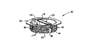
Fig. 2 is a perspective view showing the bung plug venting
device of the present invention.
Fig. 3 is a plan view of the venting device of Fig. 2.
Fig. 4 is a side elevation of the venting device of Fig. 2.
Fig. 5 is a bottom view of the venting device of Fig. 2.
DESCRIPTION OF THE PREFERRED EMBODIMENTS
In the embodiment of the present invention as shown in Figs.
1 through 5, there is provided a bung plug venting device 10,
- 2 -

2139910
constructed of stainless steel or other similar material,
threadably mounted in the top wall of a container 11. As shown in
Fig. 2, the device 10 includes a head portion 12 and a threaded
neck portion 14. Located at equally spaced intervals around the
circumference of the threaded neck portion 14 are a plurality of
milled slots 16. The depth of the slots 16 generally corresponds
to the thickness of the threads 17 on the threaded neck portion
14. In one embodiment, as shown in Figs. 4 and 5, a sealing gasket
18 fits around the upper end of the threaded neck portion 14 and
abuts the head portion 12. The head portion 12 includes an outer
rim 30 which surrounds a recessed central area 28 and located
within the recessed area 28 is a crossbar handle member 20 for
screwing and unscrewing the bung plug 10. In one embodiment of the
invention, as shown in Fig. 3, the handle member 20 is in the form
of a stamped plate 24 having a raised bar portion 26 centrally
located on the plate 24, with the plate 24 being welded or
otherwise secured to the bottom wall 22 of the neck portion 14 of
the device 10.
The slots 16 are milled into the radially outer surfaces 15 of
the threaded neck portion 14. In one embodiment, the slots 16
extend from approximately two threads down from the upper end on
the threaded portion 14 downwardly to intersect the curved sides of
the bottom wall 22 of the neck portion 14. This configuration
provides sufficient threads for sealing and, when the plug is
unthreaded approximately two threads, the internal pressure is then
relieved at a predetermined rate based on the width "w" and the
- 3 -

2139910
number of slots 16. This permits the bung plug 10 to be ventilated
at varying rates. The number of slots 16 as well as the width of
the slots 16 is determined by the capacity of the container 11.
In one embodiment of the invention, the threaded neck portion
14 of the device 10 had a diameter of approximately 2 inches and
the gasket 18 was of a polyseal material having an inner diameter
of approximately 2 inches. In this embodiment, the height of the
device 10 was approximately 13/16 inch and the height of the top of
the slots 16 from the bottom wall 22 of the neck portion 14 was
approximately 7/16 inch.
In use, when the bung plug 10 is screwed in tightly in the
position as shown in Fig. 1, there is a complete seal on the
container il. The gasket 18 seals any possible leakage along the
threaded neck portion 14. As the crossbar handle member 20 is
turned so as to unscrew the bung plug 10 for ventilation, the bung
plug l0 maintains a complete seal on the container 11 up until the
moment when the two upper threads in the threaded neck portion 14
rise above the upper surface of the container 11, at which point
the presence of the milled slots 16 causes the contents of the
container 11 to be ventilated or de-pressurized, depending on the
pressure conditions of the contents of the container 11. The bung
plug 10 may then be returned to its secure seal on the container 11
by turning the crossbar handle member 20, thus having relieved the
container 11 of pressure and having ventilated the contents of the
container 11 without having removed the bung plug 10 itself.
The invention may be embodied in other specific forms without
- 4 -

1339I0
departing from the spirit or essential characteristics thereof.
The present embodiments are therefore to be considered in a11
respects as illustrative and not restrictive, the scope of the
invention being indicated by the appended claims rather than by the
foregoing description, and a11 changes which come within the
meaning and range of equivalency of the claims are therefore
intended to be embraced therein.
What is claimed and desired to be secured by Letters Patent
is:
- 5 -

Dessin représentatif
Une figure unique qui représente un dessin illustrant l'invention.
États administratifs

2024-08-01 : Dans le cadre de la transition vers les Brevets de nouvelle génération (BNG), la base de données sur les brevets canadiens (BDBC) contient désormais un Historique d'événement plus détaillé, qui reproduit le Journal des événements de notre nouvelle solution interne.

Veuillez noter que les événements débutant par « Inactive : » se réfèrent à des événements qui ne sont plus utilisés dans notre nouvelle solution interne.

Pour une meilleure compréhension de l'état de la demande ou brevet qui figure sur cette page, la rubrique Mise en garde , et les descriptions de Brevet , Historique d'événement , Taxes périodiques et Historique des paiements devraient être consultées.

Historique d'événement

Description Date
Inactive : Périmé (brevet - nouvelle loi) 2015-01-10
Accordé par délivrance 1999-08-03
Inactive : Page couverture publiée 1999-08-02
Inactive : Taxe finale reçue 1999-04-26
Préoctroi 1999-04-26
Un avis d'acceptation est envoyé 1999-02-17
Lettre envoyée 1999-02-17
Inactive : Approuvée aux fins d'acceptation (AFA) 1999-01-28
Inactive : Renseign. sur l'état - Complets dès date d'ent. journ. 1997-09-26
Inactive : Dem. traitée sur TS dès date d'ent. journal 1997-09-26
Demande publiée (accessible au public) 1995-07-26
Exigences pour une requête d'examen - jugée conforme 1995-02-07
Toutes les exigences pour l'examen - jugée conforme 1995-02-07

Historique d'abandonnement

Il n'y a pas d'historique d'abandonnement

Taxes périodiques

Le dernier paiement a été reçu le 1999-01-08

Avis : Si le paiement en totalité n'a pas été reçu au plus tard à la date indiquée, une taxe supplémentaire peut être imposée, soit une des taxes suivantes :

  • taxe de rétablissement ;
  • taxe pour paiement en souffrance ; ou
  • taxe additionnelle pour le renversement d'une péremption réputée.

Les taxes sur les brevets sont ajustées au 1er janvier de chaque année. Les montants ci-dessus sont les montants actuels s'ils sont reçus au plus tard le 31 décembre de l'année en cours.
Veuillez vous référer à la page web des taxes sur les brevets de l'OPIC pour voir tous les montants actuels des taxes.

Titulaires au dossier

Les titulaires actuels et antérieures au dossier sont affichés en ordre alphabétique.

Titulaires actuels au dossier
CUSTOM METALCRAFT, INC.
Titulaires antérieures au dossier
ROBERT D. KNOOP
Les propriétaires antérieurs qui ne figurent pas dans la liste des « Propriétaires au dossier » apparaîtront dans d'autres documents au dossier.
Documents

Pour visionner les fichiers sélectionnés, entrer le code reCAPTCHA :


Pour visualiser une image, cliquer sur un lien dans la colonne description du document. Pour télécharger l'image (les images), cliquer l'une ou plusieurs cases à cocher dans la première colonne et ensuite cliquer sur le bouton "Télécharger sélection en format PDF (archive Zip)" ou le bouton "Télécharger sélection (en un fichier PDF fusionné)".

Liste des documents de brevet publiés et non publiés sur la BDBC .

Si vous avez des difficultés à accéder au contenu, veuillez communiquer avec le Centre de services à la clientèle au 1-866-997-1936, ou envoyer un courriel au Centre de service à la clientèle de l'OPIC.


Description du
Document 
Date
(aaaa-mm-jj) 
Nombre de pages   Taille de l'image (Ko) 
Description 1995-07-25 5 168
Abrégé 1995-07-25 1 14
Revendications 1995-07-25 4 97
Dessins 1995-07-25 2 61
Revendications 1996-08-29 3 96
Dessin représentatif 1999-07-26 1 6
Dessin représentatif 1998-08-03 1 7
Avis du commissaire - Demande jugée acceptable 1999-02-16 1 163
Correspondance 1995-03-05 11 371
Correspondance 1999-04-25 1 27
Taxes 1999-01-07 1 29
Taxes 2000-01-05 1 31
Taxes 1998-01-07 1 39
Taxes 1997-01-01 1 35