Note : Les descriptions sont présentées dans la langue officielle dans laquelle elles ont été soumises.
~t ~322
-1- Docket: 0116-95
VENTILATING ELEMENT FOR ROOFS
Background of the Invention
Field of the Invention
The invention relates to a ventilating element with a ventilator cap
5 for mounting on the ridge, hip or arris area of a roof, and which has at
least one elastically flexible sealing member that extends along a
longitudinal edge area of the cap.
Description of Related Art
Use of foam sealing members in ventil~ting elements for roofs are
10 known. The disadvantage is that for varied spacing differences and/or
sharp-edged transitions the foam, due to its structure, is not able to achieve
sufficient tightness. In addition it is also disadvantageous that the foam
undergoes an aging process and embrittles as time passes, so that age and
functional endurance are not ensured. Finally, foam requires strong
15 compression which makes it difficult to place, also accessible areas are
exposed to bird damage and weathering. Cementing the sealing members
of foam to the fan cover also entails the risk that the adhesive will detach
and the sealing members fall off.
- 2 - Docket: 01 16-95
In U.S. Patent No. 5,332,393, a ventilator cap is disclosed in which
a sealing element extending over the length of the cap on an underside
thereof is formed of a fine-fiber brush with a carrier part and a pluraIity
of elastic brush fibers in as flowtight a packing as possible. To minimi7e
the e~fects of UV radiation and considerable temperature changes (which
can cause the fibers to become embrittled, lose their resilience and break
off easily, thereby reducing the packing density and sealing efficiency of
the sealing element), a protective element is provided on an outer side of
the sealing element which influences the elasticity of the brush fibers as
little as possible. The fibers can be of the same length or can have lengths
which produce a stepped or wedge-shaped inside contour. However, here,
the disadvantage exists that the free ends of the brush fibers, therefore the
individual fiber tips, can bend, for example, when they abut obstacles such
as rough spots or edges, by which the sealing integrity is jeopardized. The
brush fibers have the property of very easily lining up, by which flow-tight
packing is no longer ensured, and moreover this makes a visually poor
impression.
On the basis of the foregoing, it is a principal object of the
present disclosure to devise a ventilating element of the
aforementioned type which is simply built, which ensures an optimum
seal, and which is homogeneously adapted to any roofing material.
The sealing member being formed is a looped filament seal.
This configuration has the advantage that undesirable
disorientations of the filaments are prevented. This is because the
loop structure has no free filament ends, and there is always a
curvature in the end region which, on the one hand, prevents
~'
3 Docket: 0116-95
unintentional back-hooking, and on the other hand, imparts a certain
coupling effect to adjacent loops, so that overall interlinking and
interlacing of the individual loops are present, benefitting each
other, especially by holding one another down, and preserving a
close, flow-tight packing. This ensures optimum integrity. The
loop filament seal, thus, has a very uniform behavior. There is
essentially no compression in the subject matter of the invention,
so that the loop filament seal is very easy to install and does not
heavily load parts mechanically. The loop filament seal consists of
filament material having an elasticity which ensures the sealing
function is established by placing the individual filaments on top
of one another, by overlapping them and so forth.
In one embodiment, the loop filament seal has loops in which
the front and back filaments do not overlap one another, the front
filament of a loop is defined as the portion which runs to the free
end of the loop; the back filament is the portion of the loop which
runs back from the free end. If there is no overlapping in a loop,
it is a so-called "meander'l arrangement; this does not mean that
adjacent loops do not overlap, which is, of course, the case for
reasons of seal integrity. Rather, in a meander arrangement, the
filaments of a loop are placed such that the front and back
filaments do not overlap or cross one another.
However, it is possible, as an alternative, for the loop
filament seal to have loops in which the front and back filaments
overlap. In this way, a so-called "mesh" loop is formed.
All possibilities of loop formation can, of course, also be
implemented in any combination on the ventilator cover, so long as
c ~
.*. . . .
- 4 - Doc~et: OI 16-95
the loop formation always leads to the individual fibers cross
linking with one another.
In accordance with a first aspect of the invention there is
provided, a ventilating element for roofs, with a ventilator cover
in one of a ridge, hip and arris area, at least one elastically
flexible sealing member being disposed along a longitudinal edge
thereof, wherein the sealing member is formed of loop filament seal
having a multiplicity of filament loops, and wherein at least some
of the loops are interconnected by means of transverse filaments.
In accordance with a second aspect of the invention there is
provided, a ventilating element for ventilating of ridge, hip and
arris areas of a roof, comprising a cover member having a central
fastening portion intermediate and interconnecting a pair of side
wall portions, each side wall portion having an elastically flexible
sealing member being disposed along a longitudinal edge thereof;
wherein the sealing member comprises a loop filament seal having a
multiplicity of filament loops arranged to produce an essentially
airflow-tight seal; wherein rows of loops are arranged in layers
which are held together at an end of the layers by a holder, the
holder and each layer extending along the longitudinal edge; and
wherein the loops are in a folded over form, the holder holding rows
of folded over loops at a fold thereof.
Embodiments of the invention will now be described with
reference to the accompanying drawings wherein:
Fig. I shows a cross section through a ridge area of the roof of a
building with a ventilator element mounted thereon;
Fig. 2 shows a schematic representation of filament patterning for
a sealing member;
n
D
_ 4a - ~'
'~_
Fig. 3 shows a schematic representation of the holder for the
filament member of Fig. 2;
Fig. 4 shows another embodiment of the sealing member in a
schematic representation in the mounted state;
Fig. S shows a modified form for an arrangement according to the
embodiment shown in Fig. 4 in the mounted state;
~,,
~40~22
..,~.
- 5 - Docket: 0116-95
Fig. 6 shows the sealing member of Fig. S in an intermediate stage
of being mounted;
Fig. 7 shows a schematic representation of filament patterning
according to another embodiment in an unmounted state;
S Fig. 8 shows the arrangement of Fig. 7 in the mounted state;
Fig. 9 shows the sealing member of Fig. 3 in the mounted state;
Fig. 10 shows an embodiment of a sealing member having angled
loops;
Fig. 11 shows an embodiment of a sealing member having helicoidal
or spiral loops;
Fig. 12 shows an embodiment of a sealing member having plaited
loops;
Fig. 13 shows a schematic representation of a sealing member which
has bunched loops in an unmounted state;
Fig. 14 shows the embodiment of a sealing member according to
Fig. 13 in a mounted state;
Fig. 15 shows a schematic of loop filaments of a sealing member
;~ which are provided with transverse filaments, the loop filaments being cut
into sections;
Fig. 16 shows an embodiment according to Fig. 15, but with an
endless filament;
Fig. 17 shows an embodiment according to Fig. 10, but with
transverse filaments;
Fig. 18 shows a sealing member with loops of uniform loop length
in an intermediate stage of being mounted;
Fig. 19 shows a sealing member corresponding to the embodiment
of Fig. 18, however with different loop length,
- 6 - Doc~et: 01 16-95
Fig. 20 shows the embodiment of Fig. 18 in the mount~d state;
Fig. 21 shows a perspective representation of another sealing
member;
Fig. 22 shows a perspective representation of the sealing mémber
according to another embodiment;
Fig. 23 shows a perspective representation of a sealing member with
different lengths of the loop such that a wedge-shaped profile is formed;
Fig. 24 shows another embodiment of a sealing member provided
with loops of different length, by which a stepped profile is formed;
Fig. 25 shows an embodiment of a sealing member with loops which
run diagonally in an intermediate stage of being mounted;
Fi~. 26 shows a diagonal loop embodiment as in Fig. 2~, however,
with loops of different length on one side;
Fig. 27 shows the embodiment of Fig. 25 in the mounted state;
Fig. 28 shows an embodiment of a sealing member with loops which
run in an extreme diagonal position;
Fig. 29 shows a seaIing member in which the loops assume a
tangled position, and therefore, are mostly randomly oriented; and
Fig. 30 shows a device for preparing a sealing member
embodying the invention.
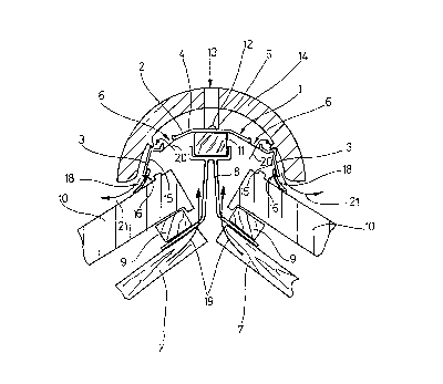
Detailed Description of the Preferred Embodiments
Fig. 1 shows a cross section through the roof of a house
in the area of the ridge. The invention relates to a
ventilating element 1 which however can be used not only
in the ridge area of the roof, but can also be used in
J I .
:. . ~ f ,
- 7 - Docket: 0116-95
other areas, for example, in the area of the hip or arris. Ventil~ting
element 1 is designed as a one-piece ventilator cover 2 which has side
walls 3 and ceiling wall 4 formed therebetween. Ceiling wall 4 is
penetrated on both sides of an attachment area 5 by ventilation openings 6.
The ridge area of the roof has angled panels 7 on which a lath
holder 8 is attached. In the attachment area of lath holder 8 are laths 9
which are used for hanging and holding roof covering material 10. Lath
holder 8 bears ridge joint panel 11 on which ventilator cover 2 is attached
by screws 12 in attachment area 5. Screws 12, at the same time, partially
attach ridge brace 13 which is used to hold ridge covering 14.
In the area 15 inside of side walls 3 of ventilator cover 2 sealing
members 16 are attached. This can be done, for example, by means of a
clip connection, a push-in connection, an adhesive conn~tion or a screw
connection. Sealing members 16 are used to seal, essentially flow-tight,
mostly irregularly sized gaps 18 between the lower end of side walls 3 of
ventilator cover 2 and roof covering material 10. To vent the roof, the air
can rise in the manner of arrows 19, pass through ventilation openings 6
of ventilator cover 2 (arrows 20) and exit to the outside in the area between
ridge covering 14 and the upper side of the respective sealing member 16
(arrows 21).
Each sealing mernber 16 is formed as
loop filament seal n. Each loop filament seal 22 is comprised of a
number of loops 23 which consist of filament material 24. Filament
material 24 is, preferably, a plastic material.
Each loop 23 consists of a front filament 25 and a back filament 26
which merge with one another in free end area 27 in turning area 28, i.e.,
D:
~ 1~0322
,~ .
- 8 - Docket: 0116-95
a one-piece, arc-shaped loop end 29 is formed on each loop 23 in turning
area 28.
Fig. 2 illustrates that individual loops 23 are formed by means of a
meandering continuous filament 30. If they are associated with a holder 31
according to Fig. 3, this is done preferably such that a clamping sheet 32
is placed under this meandering arrangement intermediate the longitudinal
extension of loops 23 and a retaining strip, for example wire 33, is placed
on the meandering arrangement such that it runs centrally to the clamping
sheet 32. If clamping sheet 32 is now folded centrally along its length,
wire 33 is pinched and with it the meandering arrangement is folded by an
angle of 180, by which continuous filament 30 is held in the area of
clamping sheet 32. Then, the arrangement according to Fig. 9 is formed,
i.e., a plurality of loops 23 are held by holder 31, front and back filan-.ents
25, 26 running roughly parallel to one another, i.e., they are held without
crossing. Of course, Fig. 9 only schematically illustrates a portion of the
loop filament seal 22 formed in this way, since only a few loops 23 are
shown. In reality, a plurality of these loops 23 are arranged on top of one
another in densely packed form and also in many layers and different
lengths so that overall a flow-tight packing is formed.
Fig. 4 shows one embodiment which corresponds essentially to the
embodiment of Fig. 9, however front and back filaments 25, 26 are laid to
cross so that a configuration approximating a figure eight results overall.
The embodiment of Fig. 5 differs from that of Fig. 4 in that the
front and back filaments 25, 26 cross twice producing just over a full
figure eight for each loop 23.
Fig. 6 illustrates the arrangement of Fig. 5 in which loop 23 is in
the intermediate state shown in Fig. 3, and as relative to the embodiment
g - Docket: 01 16-95
of Fig. 3, it is held by means of clamping sheet 32 and wire 33 and is to
be folded over centrally by 180~.
The embodiment of Fig. 7 shows a configuration of loops 23 in the
manner of a series of the lower case script letter 1. Preferably, to form a
configuration of this type continuous filaments 30 are likewise used. They
are held according to Fig. 8 by means of holder 31 in the area of their one
end.
Fig. 10 shows an embodiment in which loops 23 are not aligned in
a position which runs essentially perpendicular to the longitudinal extension
of holder 31 as is in the preceding embodiments. Instead, individual
loops 23 form an acute or obtuse angle with the longitudinal extension of
holder 31 in the mounted state and thus, diagonally to the longitudinal
extension of ventilator cover 2. Acute and obtuse angles can also be
provided alternatingly or in a stochastic distribution, by which th~
crosslinking effect is intensifi~d. Preferably loops 23 are arranged such
that they cross one another, as shown in Fig. 10. Obtaining a high packing
density is a general prerequisite for entry and flow sealing and applies to
all embodiments from Fig. 1 through Fig. 30.
Fig. 11 shows another embodiment of a loop filament seal 22 in
which individual loops 23 are formed by filaments 34 which run
helicoidally and spirally. Another embodiment of loop filament seal 22
is shown in Fig. 12 in which loops 23 are formed by filaments 34
which run in the manner of a plait or braid.
Fig. 13 shows loops 23 which are held together as bunches 36 by
means of a suitable gathering element 35. Individual bunches 36 are held
to form an overall loop filament seal by means of holder 31 (Fig. 14)
which can be formed, preferably, as a clamping sheet 32 and wire 33
~;
3 2 2
.. "
-
~ - 10- Docket: 0116-9S
which is then folded as with the prior embodiments to hold the individual
bunches 36 in an overlapping arrangement.
Fig. 15 shows an embodiment which corresponds to that of Fig. 9
with the difference that the individual loops 23 are crosslinked to one
S another by means of separate transverse filaments 37. The transverse
filaments 37 can, likewise, be formed as loops 38.
While in the embodiment of Fig. lS cut-off filaments 34 are used,
~_ in the embodiment of Fig. 16, a continuous filament 30 is used which
forms both the loops 23 and the linking loops 38. Due to transverse
filaments 37 reinforcement of the crosslinking of loops 23 is engendered.
Fig. 17 shows an embodiment in which loops 23 run at acute or
obtuse angles to the longitudinal extension of mount 31 and in which
transverse filaments 37 are not parallel to the longitudinal extension of
holder 31, as is the case in the embodiments of Figs. 15 and 16. Instead,
lS the transverse filaments 37 run at an angle, i.e., diagonally, to the
longitudinal extension of holder 31, and thus, diagonally to the longitudinal
extension of ventilator cover 2. It is also possible to form different angles,
for which an angular offset can be periodically provided or is randomly
stipulated.
Fig. 18, again, illustrates an arrangement based upon the Fig. 3
embodiment, in which, however, the packing density of the individual
loops 23 is illustrated, i.e., individual loops 23 which lie adjacent to one
another fit into one another and thus crosslink to form an integral structure.
The embodiment of Fig. 19 differs from that of Fig. 18 in that the
loops 23 used have loop lengths of different size, by which a stepped or
wedge-shaped path of the profile of loop filament seal 22 is established.
3 ~ 2
..~,
-1 1 - Docket: 01 16-95
Fig. 20 shows the sealing member of Fig. 18 in the finished state.
That is, after folding over of the clamping sheet 32.
To illustrate the dimension of thickness of loop filament seal 22,
Fig. 21 shows a perspective representation. It can be clearly seen that
5 clamping sheet 32 has a U-shaped profile when folded. The individual
loops 23 lie next to one another, within one another, and on top of one
another in an closely packed arrangement.
Fig. 22 shows another embodiment in which holder 31 is formed not
as a clamping sheet 32, but as a plastic part which is used for attachment
10 of individual loops 23, and in ~vhich loops 23 can be attached by cementing
or bonding.
Fig. 23 shows loop filament seal 22 formed in a wedge-shaped
profile which is formed by corresponding!y placin~g long loops 23 on top
of one another such that the smallest packing density is established on the
15 end of loops 23 and the largest packing density is established in the area
of holder 31.
The embodiment of Fig. 24 differs by loops 23 being arranged such
~,_ that they yield a step-shaped profile of loop filament seal 22. To form an
arrangement which corresponds roughly to that of Fig. 8, loops 23 are
20 placed as shown in ~ig. 25. They have the configuration of a large
multiple figure eight, holder 31 being located in the area of the crossing
points of the figure eight.
The embodiment according to Fig. 26 corresponds approximately to
the embodiment of Fig. 25, however the loop lengths being different only
25 on one side of the not yet folded-over loop arrangement; on the other side
are loops 23 of equal length. It is also possible to proceed such that the
individual loops 23 are laid down in a multiple Fig. 8.
- 12- Docket: 0116-95
Fig. 27 shows the embodiment according to ~ig. 2~ in the finished
state.
Fig. 28 shows an embodiment of the loop filament seal 22 in
which individual loops 23 assume an extreme angular position
relative to the longitudinal extension of holder 31, by which
manifold overlapping and interlinking appear.
Fig. 29 shows an embodiment of the loop ~ilament seal 22 in
which individual loops 23 assume a random orientation to one
another, i.e., a type of felt effect is achieved, by which extreme
coupling of indivldual loops 23 is present.
Finally, Fig. 30 illustrates one possible production
process for loop arrangements of loop filament seal 22.
Preferably, a plurality of dispenser rolls 39 are provided on which filament
material 24 is wound as continuous filaments 30. By means of a filament
layering apparatus 40 which has eyes 41 according to the number of
continuous fibers 30, and through which continuous filaments 30 run, loops
are formed, in which at the same time several loops 23 can be layered.
This is done by moving filament layering apparatus 40 accordingly by
means of device 42, which is neither shown nor described in detailed, since
the construction of such apparatus, itself, forms no part of this invention.
Likewise, the device which draws off continuous filaments 30 in the
layering process is not shown for reasons of simplification.
... ..
., ,