Note : Les descriptions sont présentées dans la langue officielle dans laquelle elles ont été soumises.
214~.4'~ 3
METHOD AND DEVICE FOR COATING A MATERIAL WEB
BACKGROUND OF THE INVENTION
Field of the Invention
The invention relates to methods and devices for
coating running webs of material, and particularly to
methods and devices for coating at least one side of a
material web by premetering an application medium onto an
applicator roll and transferring the medium onto the web in
a gap formed by the applicator roll and a counter element.
Describtion of Related Technolocrv
In the art of paper finishing, various methods
and devices are known for coating a paper web with an
application medium. The coating of the web may be
performed by applying the medium directly onto the fiber
web which loops around a portion of a periphery of a body
with rotational symmetry. Another coating method includes
premetering an application medium onto a surface of a body
with rotational symmetry. In both cases, the application
process includes two successive steps: 1) the coating is
applied in excess utilizing an application nozzle; and 2)
excess coating composition is removed utilizing an
equalizing system, typically in the form of a doctor
element; or successive doctor and blade devices. The
composition transfer or metering may be performed, for
example, in a film press. In conventional film presses,
the application medium is applied onto the surface of the
applicator roll, in which case the metering is usually
21414' 3
2
achieved by successive doctor devices. The premetering
devices are disposed on the framework of the applicator
roll and can be pressed onto the surface of the applicator
roll with the aid of cylinders or similar devices. The
premetering device may include a nozzle applicator system
in which a sizing or coating composition flows through a
special distributor (flow spreader) system into a pressure
chamber of the applicator nozzle. Such a device may also
include a doctor bar device. The application medium
arrives into the application chamber through a slotted
nozzle of the pressure chamber. The amount of sizing or
coating composition is controlled with the aid of a doctor
bar or a blade to which pressure can be applied.
Such devices may be complicated in structure,
particularly with respect to the application and metering
system and may be problematic since they utilize a metering
element that can get worn down. Therefore, keeping the
amount of film constant with respect to a function of time
can present problems and cannot be directly influenced. A
transverse profile of an applied medium on an applicator
roll can be kept constant only by tedious profile
adjustment work. Otherwise coating composition application
along a width of the machine does not necessarily occur
uniformly. Furthermore, at high solid contents or in the
case of extremely absorbent papers, there is a danger of
the formation of profile ridges, which may cause a
limitation of the minimum amount of coating composition
that may be applied. The use of a metering element that is
21414' 3
3
readily worn leads to short life spans of such a metering
element and thus to undesirable shutdown time of the
machine necessitated for replacing the metering element.
Furthermore, control of the amount of coating composition
applied to a roll is not possible without replacement of
the metering element or without tedious adjustment work.
SUMMARY OF THE INVENTION
It is an object of the invention to overcome one
or more of the problems described above. It is also an
object of the invention to keep constant the amount of film
to be transferred onto a fiber web as a function of time
and with respect to the width of the machine, that is,
transversely to the direction of movement of the fiber web.
Moreover, it is an object of the invention that the amount
of coating composition film to be applied should be
controllable for certain web widths. Furthermore, an
object of the invention is to minimize the wear of a
metering element and thus to achieve a longer time period
between required changes of the metering element. An
object of the invention is also to provide for low
operating costs and suitability for use for both coating
and starch application.
According to the invention, the metering element
is preferably strongly built, easy to handle, show little
tendency to be damaged, suitable for use at high
application velocities, easy to operate and should have
only a very small number of wearing parts.
CA 02141473 2002-07-10
4
The invention concerns a method for at least one-sided coating of s material
web
with as application medium in a two-clement applicator devioa having at least
one
applicator roll and a counter elcmeat defining a gap thr~oup~t which the
material meb is
conveyed. The inventive method includes the steps ofpremetaring the
application
3 madium onto the applicator roll and traasfetring tbo application medium onto
the material
wcb in the gap. hremetering of the application medium to the applicator device
is
pettormed by at Icast one free jot.
In an aepoct of tha prasrnt invention, tire is provided a method of coating at
least
one sido of a fibrous web with an application medium in a two-element
application
device comprising two applicator elementr which aro driven in opposite
direttioas and
togs form a gap through which tho ~bmua web is led, in which math4d the
application medium is pro-tnetcred onto at lean ono of said applicator
elamaats and is
tranaii!xrCd to the fibrous web in the gap, charactazwzed in that the pro-
metering is carried
1 S vut by means of at least one ~ jet of application medium, aimed directly
at a surface of
said at lean one applicator elemeont.
rn another aspect ef the prat invention, t6ecn is prawidod ~ for coating
at laast one side of a fibrous web with an spplicatjoa a:edium co~mpriaing:
two applicator oIdments, together forming a gap for the fibrous web to be Ied
tluough, wherein said applicator elemanta are driven in opposite directions;
wherein at least one of said applicator elements is assigned an applicator
unit;
such that
the applicator wait includes at least one device for producing a free jet
which
2S premeters the application medium onto s surface of ire ::signed applicator
element.
1n yet another aped of the prasent invention, tfi~ere is provided apparatus
for
coating at Iaest one side of a fibrous web with as application medium
comprising:
two applicator elements, together forming a gap for the $bmus web to be led
thtnugh, whareia said agpl~~ator ~xemex~ts arc driven in opposite directions;
CA 02141473 2002-07-10
4(a)
whe~reix~ at least one e~f said applicator elements is assigned an applicator
unit;
suoh that the alrplicatar unit is implcrnented as an open haadbox which
supplies the
application mewdium onto the surface of its assigned applicator element;
the opeon hoadbox iacluding a means for pre-metering the quantf ty of
application
medium applied to said surface.
In yet ~othor aspect of the invcntlon, there is provided a marhod of costing
at
least one aide of a fibrous web with an application medium in a two-element
application
dovioo compria,ing two applicator elements which are driven in opposite
directions aad
t0 together form a gap through which the fibrous web is led, in which method
the
spplication matdium is pro-metered onto at least one of said applicator
claments and is
trensfa~x~od to W a $braus web in the gap, charncterizad in that the pre-
metering is carried
out by an open ;headbox including means for rnetcriag a quantity of
application medium
applied egad at least one applfcator element.
Other object ~tcui advantages aftho invention will ba apparent to tboso
sldllod is
the att from the: following detailed description taken in conjunction with the
drawings and
the appendai cl;alma.
I~RII:?F DESCRIPTIO1~T O~ T DRAWINGiS
1!'~g. 1 is a soheunatic sectional view of a device according to the
invention.
hig. I is a schematic sectional view of a second embodiment of a device
according to the invention.
z5 Hig. 3 is a schematic sectional view of a third embodimeutt of a device
according to the invention.
F'ig. 4 is a schernatie sectional view ofa fourth embodiment of a device
according to the inv~on.
F'~(g. 5 is a sohematie sectional view of a fifth embodiment of a device
3a ~oording to the invention.
21414 3
DETAILED DESCRIPTION OF THE INVENTION
According to the invention, premetering of a
coating or other application medium is performed utilizing
a two-element applicator device that introduces the medium
5 onto the surface of an applicator roll, at least
indirectly, that is, both directly as well as indirectly,
by application of the application medium with the aid of at
least one free jet. The use of a free jet provides the
advantage of direct control of the applied amount and thus
the thickness of the applied film on the surface. Also,
the applied amount and film thickness may be altered by
changing certain parameters of the jet, for example,
discharge cross-section, discharge velocity and application
angle of the free jet, in relation to the rate of rotation
of the applicator roll.
The free jet can be directed either directly onto
the surface of an applicator roll or onto the surface of a
transfer roll, which, again, transfers the application
medium at least indirectly, that is, directly or through
another transfer roll, onto the surface of the applicator
roll. The latter variation (indirect application) also
provides the advantage of further metering action,
especially the extension of the applied film based on the
velocity difference of the surfaces of the applicator roll
and the transfer roll obtained by suitable adjustment of
the ratio of the diameters of the applicator roll and
transfer roll.
21414' 3
6
According to the invention, a device for
performing at least one-sided coating of a material web
with an application medium includes first and second
applicator elements driven in opposite directions and
defining a gap for the passage of a material web
therebetween. Also, an applicator unit cooperates with at
least one of the applicator elements. The applicator unit
includes an apparatus for producing a free jet. The free
jet thus indirectly premeters an application medium onto
the surface of the applicator element cooperating with the
free jet. The apparatus for producing a free jet can be
assigned directly to the applicator element (the free jet
is directed directly onto the surface of the applicator
element) or can be assigned to this indirectly by
connecting at least one transfer element before it.
Preferably, the two-element applicator device is
designed in the form of a two-roll applicator arrangement,
that is, two applicator rolls with parallel axes are driven
in opposite directions and form a press gap through which
the material web is conveyed. The application of the
application medium onto the web is accomplished by passage
of the web through the press gap during which the
application amount that was premetered onto the surface of
the applicator roll is transferred onto the web. Such a
device is suitable for one-sided coating, as well as for
two-sided coating of fiber webs with application
composition. The same or different application media can
be applied to opposite sides of the web. According to the
CA 02141473 2002-07-10
7
invention, the following is possible:
1 ) The application of a medium is performed directly, i.e., directly onto the
surface of an applicator roll; and
2) The application is done here indirectly, i.e., onto the suxfaea of x
transfer
roil assigned to the applicator roll.
Possibility (2) above provides the advantage of additional tnatcring action
with
suitablo design of the ratio of the diantetera of the applicator roll xnd the
transfer znll, as a
rule, in the form of stretching or extending the film by the transfer roll.
This is 8spc~cially
advantageous when a particularly thin applied film is desired on the surfisce
of the fiber
web.
'There are two prePcrrcd variations fur the design of the device for produci»g
a
free jet:
1 ) A free-jot nozzle device; and
2) A clwcd headbox with a pressure-loaded central oontainear and a va~iably
adjustable outlet opening.
The flee jec nozzle device is a pure applicator device with its own supporting
body, which includes, for example, a flow spreader and a slotted nozzle
extending over
the width of the machine (i.e,, the length of an applicator roll}. This device
may be
designed ae disclosed is US Patent Nos. 3,418,970, 3,521,602 and 4,231,318.
The
application of a medium is
21414' 3
8
performed without the nozzle coming in contact with the
surface of the applicator element. The free-jet nozzle
device can be displaced in a radial direction with respect
to the surface of the applicator roll and can be rotated
around a certain axis in such a way that the application
angle can be varied and adjusted with respect to the
surface of the applicator roll. Preferably, the nozzle
device is disposed with respect to a surface of an
applicator roll (as shown in U.S. Patent No. 3,418,970) in
such a way that a converging gap is formed in the direction
of application, that is, in the direction of the movement
of the roll, between the surface of the applicator or
transfer roll and the free-jet nozzle device.
Furthermore, a nozzle channel of the nozzle
device, i.e., a connecting line or tube between the flow
spreader and the nozzle exit can be curved. The curvature
of such a channel runs essentially in a direction
converging to the applicator roll or transfer roll. Then,
in this method, a low-air layer lies against the roll and
an air-rich layer is toward the outside thereof.
The metering action of the two systems during
application is determined by various factors. These
include:
1) The flow or discharge cross-section from the
free-jet nozzle or headbox container;
2) The discharge velocity of the application
medium;
214 ~ 9~'~ 3
3) The pressure in the flow spreader or
container; and
4) The rate of rotation of the applicator roll.
A change in the discharge cross-section and in
the rate of rotation of the applicator roll or transfer
roll can be realized simply with constructional measures,
while the change of the discharge velocity should be
considered as a function of the discharge cross-section and
of the design of the nozzle or of the container (especially
the cross-sectional changes between the flow spreader or
container and discharge cross-section).
According to another aspect of the invention, the
two-element applicator device can include an applicator
roll, which, together with a belt moving therearound, forms
an extended press gap for the passage of a material web
therethrough. Then, preferably, the application of the
free jet is onto the surface of the applicator roll, but
application onto the web can also be considered under
certain circumstances. Such a device is also suitable for
one-sided and two-sided coating of material webs.
Preferably, according to the invention, devices
for producing the free jet are disposed in the vicinity of
the surface of the applicator roll or transfer roll which
lies in the direction of rotation of the rolls, in the
region before the press gap inlet. Arrangement in areas
that are removed from the inlet of the press gap are also
conceivable. In this case, preferably, additional
equalization devices, for example, in the form of air
to _ 2149.4" ~
brushes, are used on the roll surface to make the applied
film uniform.
Application of a medium according to the
invention with the aid of a free jet onto the surface of an
application element provides the advantage of direct
controllability of the premetering of the application
medium onto the surface of an applicator element and thus
of premetering of the applied amount to be transferred in
the press gap. Furthermore, the system according to the
invention provides the advantage that the amount of film to
be applied can be kept constant as a function of time and
along the width of the roll. The application and metering
system is characterized by a low number of wearing parts
and thus by longer time periods between the required change
of the metering elements. The adjustability of the size of
the discharge openings as well as changes in position with
respect to the applicator element can be realized easily
from the constructional point of view. The method
according to the invention is suitable for coating
compositions as well as for starch.
For application of a medium according to the
invention with the aid of an open headbox, additional
precautions are taken in order to achieve the desired
direct influence on metering. Additional damping or other
perturbing elements can be included in the discharge area
from the open container.
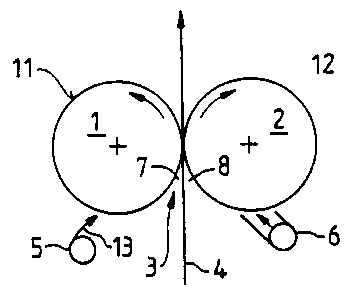
With reference to the drawings, Fig. 1 shows a
two-roll applicator device with a free-jet nozzle device
CA 02141473 2002-07-10
11
assigned to ono of the applicator rolls and a short dwell time applicator
(SDTA) with a
doctor assigned to the other applicator roll. An applicator roll 1 and an
applicator roll 2,
which ere arranged so that their axes arc parallel to each other and arc
supported
rotatably. The rolls l and 2 define a roll gap 3 for the passage of a material
or fiber web,
especially a paper web 4 therethroltgh. The two applicator rolls 1 and 2 ere
driven in
directions opposite to each other and indicated by arrows a and b.
Essentially, an
applicator unit or apparatus 5, b for a flowable medium is disposed in the
vicinity of the
roll periphery of each roll 1, ~ that moots f3~om down upward. ?he fiber web 4
is guided
thmugh tho roll gap 3 from down upward. In regions '1, 8, which are forrtled
by the roll
L O gap 3 with the fiber web 4, a film of a flowable modium is applied through
the roll
surfaces, onto both aides of the ljber web 4. By passing the fiber web 4
upward through
tho roll gap 3, the application medium, for example, a coating composition, is
applied at
the desired thickness onto the fiber web 4 corresponding to the distances of
the rolling
circles of both the rolls 1 and 2.
The applicator apparatus 5 is designed as a free-jet nozzle device. The nozzle
channel of the free jet nozzle devioo 5 is preferably curved. The froe jet
indicated by an
arrow 13 is shown Schematically. The applicator apparatus 6 is designed as an
STDA
with doctor, for example, as disclosed in DE 42 34 276 published on March 17,
I99a.
The coating composition i~ applied on each roll surface 11
21414' ~
12
and 12 of the rolls 1 and 2.
Fig. 2 shows an embodiment of a device according
to the invention which is analogous to the device shown in
Fig. 1. However, the device of Fig. 2 also includes
additional equalizing devices. Therefore, the same
reference numbers are used for the same elements in both
Figs 1 and 2. However, in Fig. 2, the fiber web 4 is
guided through the press gap 3 from the top toward the
bottom. In the region of the lower area of the part of the
roll periphery or of the roll surfaces 11, 12 of each roll
1, 2, which runs from down upward, an applicator unit 5a
and 5b, respectively, is disposed for the application
medium, for example, a coating composition. In this case,
in regions 7, 8, formed by the roll gap with the fiber web,
a film of a flowable medium is applied onto the fiber web
4 through roll surfaces 11 and 12, respectively. In
addition, in the vicinity of the roll surfaces 11 and 12,
respectively, which are disposed downstream of the
applicator devices 5a and 5b with respect to the direction
of rotation of the rolls as indicated by arrows a' and b',
additional equalizing devices 14 and 15, respectively, are
provided in the form of air brushes. The air jets produced
by the air brushes 14 and 15 make the applied coating
composition more uniform before it is transferred onto the
fiber web 4 in the roll gap 3.
Fig. 3 illustrates a two-roll applicator device
according to the invention having additional transfer rolls
which rotate in a direction opposite to that of the
21414' 3
13
applicator rolls, and define a gap therewith. The basic
structure of the device of Fig. 3 corresponds to the
structure of the device shown in Fig. 2 and therefore the
same elements have been assigned the same reference
numbers. Transfer rolls 16 and 17, with respective
applicator devices 5a and 5b, in the form of at least one
free-jet nozzle, are assigned to the applicator rolls 1 and
2, respectively. The applicator rolls 1 and 2 and
respective transfer rolls 16 and 17, define gaps 30 and 31,
respectively. Each of the transfer rolls 16 and 17
preferably have a smaller diameter than the respective
applicator rolls 1 and 2. As a result, there is always a
velocity difference between the surfaces 11 and 18 as well
as the surfaces 12 and 19, between applicator rolls 1 and
2 and transfer rolls 16 and 17, respectively. This
velocity difference contributes to stretching or extending
of the coating or other application film and thus to an
additional metering effect.
Fig. 4 illustrates a two-roll applicator device
with a closed headbox cooperating with one applicator roll
and an open headbox cooperating with the other applicator
roll. In particular, Fig. 4 shows the possibility of
premetering a coating composition directly onto an
applicator roll of a two-roll applicator device using a
closed headbox 19. The basic structure of the two-roll
applicator device corresponds to that shown in Figs. 1 to
3 and therefore the same elements have been assigned the
same reference numbers. Introduction of a coating composi-
2141~'~~
14
tion onto the roll 2 is performed directly onto the surface
12 of the applicator roll 2. The headbox 19 includes a
pressurizable container 20 with a discharge line 21
extending essentially over the entire width of the machine.
The flow-through cross-section of the discharge line 21 has
a variable cross-section, but is constant over the width of
the application.
The application of a medium onto the applicator
roll 1 is performed with the aid of an open headbox 25,
which has, for example, a central open container 26 with a
separating weir and a discharge element 27 through which
coating composition flows onto the surface 11 of the
applicator roll 1.
In order to adjust metering action, additional
means are necessary at the headbox (not shown). They are,
for example, a diaphragm assigned to the discharge element
27, which acts as a damper.
Fig. 5 shows a two-element applicator device
consisting of a roll and belt cooperating with a free-jet
nozzle device. Fig. 5 shows a two-element applicator
device which includes an applicator roll 1, which forms an
extended press gap 23 with a revolving belt or wire 22. A
free-jet nozzle device 5a is assigned to cooperate with the
applicator roll 1 and is disposed in the vicinity thereof.
The rotating endless belt 22 is coated by passing the belt
through a container 28 filled with a medium, for example,
a sizing suspension, and the amount of sizing that is
carried away by the belt 22 is equalized with a blade 24,
214 ~. 4'~ 3
which is disposed downstream of the container 28 with
respect to a direction of movement of the belt 22.
The embodiment of the device according to the
invention shown in Fig. 5 is preferably suitable for two
s sided coating with different application media, while the
embodiments shown in Figs. 1 to 4 are preferably suitable
for two-sided coating with the same application medium.
However, here, too, one can consider different and/or only
one-sided coating. The embodiments shown in Figs. 1 and 4
10 provide the possibility to assign the same applicator units
to the two applicator elements.
The foregoing detailed description is given for
clearness of understanding only, and no unnecessary
limitations should be understood therefrom, as
15 modifications within the scope of the invention will be
apparent to those skilled in the art.