Note : Les descriptions sont présentées dans la langue officielle dans laquelle elles ont été soumises.
21~236~
~. ~-...-..
A~en~'~ Ref: F'OO~PC~
Fl LTER J UG
This invention relates to a filter jug of the type which includes a water filter medium
and to a container for the filter medilJm to be used in the jug. Such jugs are filled
with water, e.g. from a domestic tap and the water is passed through via the filter
medium so as to improve the quality of the water for drinking. The filter medium is
typically housed in a moulded canister having perforations for the passage of water
~ therethrough, the canister being received in a suitably shaped chamber. The filter
medium needs to be replaced periodiocally and the used filter in its canister must be
discarded .
GE~-A-606923 discloses a portable filter unit comprising a container of perviousfabric having an upper compartment for the impure water and a lower compartment
for the filtered water, the compartments being separated by a filter through which
the water flows. GB-A-654012 discloses a filtering device comprising a reservoir for
filtered liquid, an inner perforated cage within ~he reservoir and a removable
container of granulated filter medium inside the cage. GB-A-71203~ discloses a
filtering device in the form of a beaker having a permeable base and a packing of
active carbon between two perforated surfaces located near the base. GB-A-
2192808 discloses a filter to remove impurities from water to transport live fish. The
filter comprises a column with an inlet near the base and an outlet near the top, the
column containing arcuate apertured channels containing sausage-like filter bagscontaining particulate filtration medium. US^A-4094779 discloses a filtration system
utilising an inverted upper chamber mounted on a stand above a lower chamber, a
filter containing active carbon being disposed between the two filters. US-A-
. ~E~O S~EEI
,.,.
-` 21~2362
I . ~....
4605499 discloses a filter unit comprising a pouch containing filter medium and
means to suspend the pouch in the mouth of the container to receive water.
I ~
EP A 0349315 discloses a filter cartridge for a liquid purifier. comprising a cup like
container having a depending baffle. In use liquid passing through the cover flows
downwardiy inside the baffle, passing through liquid treatment medium with which
the cartridge is filled, and then upwardly between the outside of the baffle and the
, ~ ~ .
container wall~ EP-A-0285908 discloses a container to purify water having a
receiving chamber conta,ning a filter cartridge filled with purifying agent~ the
cartridge having a foil closure that is pierced by a projection in the chamber.
;`'`~
There: remains a need for an efficient filter jug that can be easily used and
;~ maintained and which includes a filter element which is efficient in use and can be
discarded in an environmentally acceptable way.
Accarding to the one aspect of the invention, there is provided a filter jug to contain
water or other liquid, the jug comprising a first compartment to receive liquid from a
supply, a second compartment to hold filtered liquid to be poured from an outlet of
the second compartment and a filter chamber through which liquid must pass from
the first compartment to the second compartment. the filter chamber having a
r~ removable lid with a projection extending into the chamber and the chamber
~,
containing a filter medium, characterised in that the filter medium is present in a
flexible bag having a liquid-pervious wall and that the projection of the removable
lid of the filter chamber is shaped and dimensioned to extend into the chamber to
. ~
; ~ urge the flexible bag against the walls of the chamber so as to eliminate air gaps
-,
~ ~; through which water could bypass the filter medium in the bag~
`.
~,
~,
A~'N~E~ SHEE~
::
- 21~2362
- 2A -
Preferably the bag 5 is made of textile or synthetic material throughout so that the
bag can be inserted in the chamber in any orientation.
AMENDED SHEET
21 4 2 3 6 2 PCI/GB93/01685
In ~1 preferred feature, the filter chamber includes deformations to engage or support the
flexible bag. Ln a preferred embodirnent the chamber includes a removable wall, typically
the top, and having a projection extending into the charnber and shaped to urge the flexible
bag aga~nst the other walls of the chamber so that ~here are no gaps through which liquid can
bypass the filter medium.
Preferably, the filter medium is adapted to remove solids and/or gases from the liquid to be
treated.
In a particularly preferred feature the first compartment is a removable inner housing
dimensioned for reception in the upper part of the second compartment. Preferably. the filter
chamber depends from the underside of the ~lrst compartrnent.
In another aspect the invention provides a container containing a particulate filter medium for
.
use in a filter jug characterised in that the container comprises a flexible bag having a wall of
liquid-pervious material.
Advantageously, the bag is forrned from a single blar,~k of substantially rectangular form
which has been folded along the transverse centre axis and sealed along its margins and at its
overlapping edges whereby only a single transverse seal is forrned so that the flexible bag
may be compacted in a filter chamber without overlapping wall portions of the bag which
would restrict access of the liquid to the contained flter medium.
In a much preferred feature, means are present to record the usage of the filer mediurn or the
passage of time since the filter medium was installed. Preferably, the means comprises a
marked rotary wheel mounted on a lid for the jug.
.
` SUBSTITUTE SHEET
.~ WO 94/042A5 21~ 2 ~ 6 ~ - PCr/GB93/01685
~,
In order that the invention may be well understood it Will now be described by way of
example with reference to the accompanying diagramrnatic drawings, in which:
Figure 1 is a side elevation of the container in assembled condition;
Figure 2 is an exploded perspective view of the container of Figure l;
Figure 3 is a side elevation, partly in section, of the area marked III on Figure 2;
Figure 4 is a side elevation, partly in section, of the area marked IV OII Figure 2;
Figure S is a partial exploded view of another embodirnent of the invention;
Figure 6 is a plan view of the lid of the filter chamber of Figure 5, and
Figure 7 is a vertical sectional elevation of the filter charnber of the embodirnent of
Figure 5.
The same reference numerals are used to describe the sarne parts of the different
embod~nents~
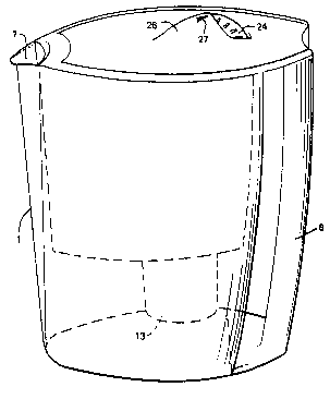
The container comprises a juglike main housing 1~ The housing is of rounded triangular
shape as seen in plan, having a front wall 2 and a rear wall 3. The housing forms the second
compartment of the jug. A top e~tension 4 and a parallel bottom e~tension 5 project from
the rear wall 3 on to which the sides of a handle 6 can be engaged. The top of the front wall
.
~ WO 94/04245 214 2 3 6 2 PCI/GB93/01685
~;,,` S
of housing 1 defines a spout 7. An inner housing g forrns the first compartment and
comprises a body of substantially the sarne shape as the main housing, but of relatively
reduced height, having a flat front face 9 at the top of which is a flat ledge 10 having a
concavely curved edge 11 which in co-operation with the spout 7 defines an outlet. The top of
the inner housing 8 has side shoulders 12. ~he upper periphery of compartrnent 8 engages the
upper periphery of compartment 1 when the former i~ positioned in the latter.
A cylindrical extension 13 depends below a hole 14 in the floor 15 of the inner housing and
- defines a fil~er charnber or sump. As can be seen in Figure 2, the floor 15 has a depression 16
in the region of the hole 14, and a disc shaped lid 17 is present to fit over the hole. The floor
18 of the extension 13 has an upwardly-extending frustoconical column 19 in the top of which
are holes 20. The extension 13 thus def~es a charnber having a perforate region in its floor,
adapted to receive a sealed fle~ible bag B containing a filter treatrnent agent. The bag has a
water-pervious wall made of textile or like material resembling a tea bag, and contains say
charcoal or like water treatment agent. The bag is sealed by a s~ called transwrap seal the
effect of which is to avoid e~ccess wall material.
A lid 21 is dimensioned to fit over the main housing 1 by engaging the shoulders 12 on the
inner housing and aligned shoulders 22 on the handle 6. The lid 21 has a concave front wall
23, leaving an open area to overlie the spout 7.
A wheel 24 is mounted on an axle 25 (Figure 4) below the lid. A shroud 26 is present on top
of the lid, dimensioned so ~hat only part of the wheel is exposed. The wheel is marked with
numerals 1 to 31, corresponding to the maxirnum days in the month, and is used to indicate, in
co-operation with a marker 26A on the shroud the day in the month which the treatment
agent was last replaced. (The agent should usually be replaced monthly).
SUBSTITUTE SHEET
Wo 94/~424s 21 4 2 3 6 ;~ pcr/GB93/ol68s f-~
To add the treatment agent B the lid 21 and 17 are removed, the bag B dropped in the
charnber and lid 17 is replaced. Water is then run in through the housings to flush the system
through. The marker is then set tO the date. The jug is filled with water from the usual
htchen tap and then lid 21 is replaced. Because the inner housing 8 and the chamber 13 are
relatively wide there is no delay in filling water and trapped air can escape via the
passageway between the main housing 1 and the inner housing 8 and the spout 7. The jug can
then be stored in the refrigerator. When after rnultiple fillings of the jug the b,ag B needs to
be discarded, it is simple to do so, and there is no environmental problem in that the wall of
the bag will decompose and the charcoal is not harmful. The amount of waste is negligible.
In the embodiment of Figures S to 7 the filter jug comprises a second compartrnent 1 which is
the main housing of the jug. It is of generally oval plan shape and has the sarne basic plan
shape as that of the inner housing first compartment 8 (see Figure S) and is a little lar~er to
receive the first compartment 8.
The upper rim of the compartment 1 defines the spout 7 and has an outward rear top
projection 4 which is joined to a corresponding rear bottom projection 5 by handle 6.
:
An integrally forrned filter charnber 13 depends from the floor 14 of the inner housing 8.
Chamb~r 13 has a generally cylindrical wall tapering towards its base 31 and defines at its
upper end an annular shoulder 32 to receive a lid 33 to be described below. The base 31 has a
number of perforations 34 to allow liquid to pass out of the chamber. A flexible sealed bag
B containing filter medium can be placed in charnber 13. The lid 33 is of generally oval
shape and has a central hump 35 surrounding by perforations 36 to allow liquid tO pass
through into the charnber 13. An air hole 37 is also provided to aid water flow. The lid 33
SUBSTI~UTE SHE~ET
f-- WO 94/04245 21 4 2 ~ ~ 7 PCI/GB93/01685
has an annular depending peripheral flange 38 which extends into the chamber 13 and locates
around shoulder 32 when the lid is in position. An annular projection 39 depends from the
underside of the lid 33 to urge the flexible filter bag B into contact with the inner wall of
charnber 13 (see Figure 7) until there are no air gaps through which water can bypass the
. filter medium, e.g. charcoal. in the filter bag B.
This embodirnent is used in the same way as the first. In this case the wheel is marked with
an arrow of increasing width and is moved each tirne the jug is f~ed, and when the arrow
disappears from view (because of the shroud) the user realises the bag B needs to be
replaced.
The invention is not lirnited to the embodiment shown. A spou~ need not be present so that
the jug is like a bottle. A handle may be present on the lid 33 to ease removal. The bag B
can be used in jugs of a shape di~ferent from that shown. The filter charnber may be a
detachable component of the jug.
:
i
SUBSTITUTE SHEE~