Note : Les descriptions sont présentées dans la langue officielle dans laquelle elles ont été soumises.
- 21~25~5
METER FOR NEAS~RING POWER CONSUMPTION
OF AN ELECTRICAL APPLIANCE
FIELD OF THE lNv~NllON
This invention relates to a meter for measuring
power consumption of an electrical appliance.
BACKGROUND OF THE lNv~NllON
Electrical appliances differ widely with respect
to the amounts of electricity which they consume, which,
in turn, determines the cost of rllnn;ng the appliances.
However, in most cases, the amount of electricity consumed
by an appliance is not readily apparent to a consumer. It
would be useful if a consumer had means at his disposal by
which electric power consumption could be measured, in
which case a consumer could take steps to use higher power
consumption devices more sparingly in order to save costs.
This would result in a general saving of energy, which is
in the public interest.
It is accordingly an object of the present
invention to provide a power meter which readily provides
a consumer with data regarding the power consumption of an
electrical appliance.
SUMMARY OF THE lNv~NLlON
According to the invention, there is provided an
electric power meter, comprising a body member; prongs on
the body member for insertion into an electric wall
socket; a socket on the body member for receiving the
plug of an electric appliance, said socket being in
electrical communication with the prongs for transferring
electric power from the prongs to said socket; current
21425~5
measuring means in the body member for measuring electric
current flow between said prongs and said socket on the
body m~mher; and timing means for measuring the duration
of said electric current flow.
Also according to the invention, there i8
provided an electric wall switch assembly, compriæing a
wall plate for mounting on a wall; an electric switch on
the plate; means for connecting the switch in series with
an electric conductor for controlling the flow of electric
current through the conductor; current measuring means for
measuring electric current flowing across the switch; and
timing means for measuring the duration of said electric
current flow.
Further according to the invention, there is
provided an electric wall plug assembly, comprising a wall
plate for mounting on a wall; a socket on the plate for
connection to an electric power supply, said socket being
adapted to receive the plug of an electric appliance;
current measuring means for measuring electric current
flow through the socket; and timing means for measuring
the duration of electric current flow through the socket.
According to a further aspect of the invention,
there is provided an electric power meter comprising a
body member, a first display on said body member to
display the cost per unit of electric power to be measured
by said power meter, a second display on said body member
to display the total cost of power consumed by an
appliance operably connected to said power meter and an
adjuster to change the cost per unit of electric power in
said first display.
According to yet a further aspect of the
invention, there is provided an electric power meter
comprising a body member, a first display on said body
21425g5
member to display the total power consumed by an appliance
operably connected to said power meter over a
predetermined period of time and a reset to reset said
first display to zero when it is desired to commence the
recordation of said power consumed.
Further objects and advantages of the invention
will become apparent from the description of preferred
embodiments of the invention below.
DESCRIPTION OF THE DRAWINGS
Figures lA to D are front, side, top and rear
views of a power meter according to one embodiment of the
invention;
Figure 2 is a schematical illustration of the
electrical circuit of the power meter of Figure 1;
Figure 3 is a front view of a power meter
according to another embodiment of the invention;
Figure 4 is a front view of a power meter
according to yet another embodiment of the invention;
Figure 5 is a front view of a power meter
according to another embodiment of the invention;
Figure 6 is an isometric view of an electrical
appliance incorporating a power meter according to the
invention;
Figure 7 is a front view of a power meter
according to yet a further embodiment of the invention;
21~2S~5
Figures 8A, 8B and 8C are front views of the
power meter according to yet a further aspect of the
invention; and
Figure 9 is a front view of the power meter
illustrating a bAnk;ng or "fuel" gauge according to a
further aspect of the invention.
DETAILED DESCRIPTION OF PREFERRED EMBODIMENTS
With reference to Figures lA to lD, reference
numeral 10 generally indicates a power meter comprising a
body member 12 provided with prongs 14 on its rear side
for insertion into an electric wall socket (not shown).
An electric socket 16 is provided on the top of the body
member for receiving the electric plug of an electrical
appliance (not shown).
The power meter 10 is further provided with two
displays on the front of the body member 12. The first
display 18 indicates cumulative electric power consumption
and the second display 20 indicates the time period over
which the electric power has been consumed.
The power meter 10 further includes a power bar
22 which comprises a row of five LED's. The two LED's on
the right hand side, indicated by reference numeral 22.1
are red, the two LED's 22.2 on the left hand side are
green, and the LED 22.3 in the centre, is white. The
purpose of the power bar 22 is to indicate when a high or
a low power consumption device is connected, by either
lighting up the red or the green LED's. In an
intermediate condition, the central white LED is lit up.
The power bar 22 therefore gives a qualitative indication
of power consumption. Thus, when very high power
consumption appliances are connected, the rightmost red
LED 22.2 will be lit up and in less severe conditions, the
21425~5
next LED 22.2 will be lit up. On the other extreme, when
very light power consumption appliances are connected, the
leftmost LED 22.1 will be lit up and then the next LED
22.1, as the case may be. Alternatively, the operation of
the power bar 22 may be cumulative, e.g. if an electrical
device is of intermediate power usage, both the green
LED's 22.2 and the white LED 22.3 may light up.
The working of the power meter 10 will now be
described with reference to Figure 2.
To determine the amount of power consumed by an
appliance, the power meter 10 makes use of the fact that
an alternating current in a wire generates a proportional
magnetic field, and vice versa. Since the line voltage is
known for the application at a particular location, the
power may be calculated from the amount of current
supplied to the appliance.
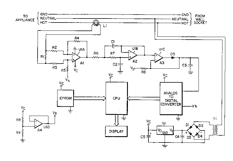
Referring to the schematic in Figure 2, L1 is a
coil which is wound around a toroid. The conductor for
the live connection of the appliance passes through the
centre of the toroid. An alternating current passing
through the live conductor will create a proportional
magnetic field in the toroid, which will in turn induce a
proportional alternating current through L1. This current
provides an alternating signal across resistor R1. The
voltage is then amplified with reference to Vh which is
half the supply voltage Vc. Reference voltage Vh is
formed by the resistors R8 and R9, and is buffered by the
operational amplifier A4. The high gain differential
amplifier is composed of operational amplifier A1 and
resistors R2, R3, R4 and R5. After amplification, the
signal is put through a low pass filter to eliminate any
transients. The low pass filter is made up of operational
amplifier A2, resistors R6, R7 and capacitors C1 and C2.
The final step in processing the signal is performed by
21425~5
operational amplifier A3 which in conjunction with diode
D5, reæistor R8 and capacitor C3 rectify the alternating
signal with reference to voltage Vh. The capacitor C3 is
used to hold a DC level which is equal to the peak AC
level. This DC voltage level is input to an analog to
digital converter which provides a digital representation
of the analog voltage to the processor.
The CPU along with its EPROM provide the
computational ability for the system, calculating the
power consumption based on the digital value provided by
the analog to digital converter. This information is then
sent to the display as watt-hours consumed. The proceæsor
also uses an internal clock to keep track of the amount of
time that the appliance has been plugged in, and this is
also sent to the display.
The DC power to run the electronics is derived
from the AC lines. As seen in the schematic, the power
transformer T1 is used to step down the line voltage.
This is then rectified and filtered by diodes Dl, D2, D3
and D4 and capacitor C4. Voltage regulator U1 provides a
regulated output Vc, which is filtered by capacitor C5 and
supplied to the electronics.
With reference to Figures 3 and 4, two
alternative embodiments, generally indicated by reference
numerals 30 and 40 reæpectively, are shown. The power
meters 30 and 40 operate in a fashion similar to that of
power meter 10. However, the power meter 30 is in the
form of a wall switch. It comprises a plate 32 for
mounting on the wall by means of screws 34 and it includes
a manually operated switch 36 for switching electric
current supply on or off. As is the case with the power
meter 10, the power meter 30 also has displays 18, for
displaying cumulative electric power consumption and
indicator 20 for indicating the time period during which
21425~5
the electric power has been consumed. It also has a power
bar 22. The electric current flowing through the switch
36 is measured as described with reference to Figure 2.
The wall plate 32 may be provided with more than one
switch 36.
With reference to Figure 4, the power meter 40
is in the form of an electric wall socket. It comprises a
plate 42 for mounting on a wall by means of a screw 44 and
it has a electric socket 46 for receiving the plug of an
electric appliance. It also includes a first display 18,
for indicating power consumption, and a second display 20,
for indicating time duration, as well as a power bar 22.
The electric current flowing through the socket 46 when a
plug is inserted is measured as described with reference
to Figure 2. The wall plate 42 may be provided with more
than one socket 46.
Instead of being built into a wall switch or
plug, as in Figures 3 and 4, respectively, the power meter
can be provided as a unit on its own, a shown in the
embodiment of Figure 5.
In this case, the power meter can be installed
next to a wall switch or wall socket, e.g. if componentry
is too large to fit into an existing wall switch or
socket.
With reference to Figure 6, a further embodiment
of the invention is shown. In this embodiment, the power
meter is built into an appliance, such as a microwave oven
50 in the present example. The first and second displays
18 and 20 are provided on the body of the microwave oven
50 and display the electrical power consumption and time
duration. The appliance may be any other electrically
powered device such as a clock radio, electric lawn mower
or dishwasher.
2142545
.
With reference to Figure 7, a further embodiment
is shown which comprises a panel 60 having separate
displays 18 and 20 for different electrical appliances,
such as an electric furnace, hot water heater, etc. Thus,
the electric consumption of a variety of different
appliances can be measured. The panel 60 may, for
example, be connected up to a household fuse box to
indicate the power consumption of different electrical
appliances associated with the different fuses in the fuse
box. It is also contemplated that the panel 60 could be
operated by sen~; ng signals along the existing electrical
wiring from wall plugs, etc. being monitored, to the panel
60 for computation and display.
A further aspect of the invention is illustrated
in Figures 8A, 8B and 8C which illustrate a power costing
embodiment which may be conveniently used with the power
meter according to the invention generally shown at 70.
The power meter 70 illustrated in Figure 8A
includes a power consumption display 71 and an adjustment
panel 72 which will be described in greater detail
hereafter. The power meter 70 further includes an
operating time display 73 as will also be further
described.
The power consumption display 71 is used to
display the total power used by the appliance to which the
meter 70 is connected. This is illustrated in Figure 8A.
Alternatively, the total cost of the power used as
illustrated at 74 in Figure 8B could be displayed.
Finally, the dollar cost per unit of power as illustrated
at 80 in Figure 8C could be displayed. Each of the three
functions may be viewed individually by the intermittent
pressing of push button 81 which selects the desired
display.
2142545
For example, it will be assumed that the cost
per unit of electricity is known and that such valve is
different from the cost per unit of electricity
illustrated in Figure 8C, namely $5.94/KWH. Push button
81 is pressed until it brings up the cost per unit
electricity 80 and displayed in Figure 8C. Thereafter,
the power adjustment panel 72 is operated upwardly or
downwardly according to the arrows until the proper cost
per unit power appears in display 80. This is the basis
for initiating operation of the total power usage as
displayed in Figure 8A or the total power cost as viewed
in Figure 8B. Reset push buttons 82, 83 are utilized to
reset to zero the display of cost 74 or the display of
total power used 71, respectively.
In operation, the correct power cost per unit of
electricity is selected in display 80 (Figure 8C) and push
button 81 is operated until the total power usage 71
(Figure 8A) or total power cost 74 (Figure 8B) is
displayed as desired by the operator. Push button 82 is
then depressed which zeros display 74 or 80 and operation
of the power meter 70 is commenced, the total power usage
71 or the total power costs 74 being displayed as desired.
Likewise, the time display 73 is returned to zero by
pressing push button 83. Display 73 shows the period of
time over which the power cost or power use has been
measured. It is contemplated that the costing
calculations and display could be likewise conveniently
used with the other embodiments of the power meter herein
described.
A further aspect of the invention is illustrated
in Figure 9 where the power meter is generally shown at
90. In this embodiment, the power meter 90 hag a bAnk; ng
or "fuel gauge" 91 which displays the amount remaining of
a predetermined monetary amount of electricity to be used.
For example, the user may wish to push in push button 92
2142~5
-
- 10 -
which will then show the gauge full for a cost of $5.00.
When the power consumed is such that $2.50 of the $5.00 is
used, the gauge 91 will illustrate the power left and
consumed as illustrated in display 91 in Figure 9. When
the total $5.00 is used, the gauge 91 will show zero.
Likewise, push buttons 93, 94 and 95 may be used to set up
additional costing reference values for the "full" gauge
91 as indicated.
It is contemplated that all of the embodiments
may be utilized with an external or internal located
computer which would interface with the various units or
wall switches. This could be particularly useful in a
commercial environment where offices may be shared by
different companies. In this event, it is contemplated
that the units or wall switches could be installed in each
office and the power usage in the respective offices would
be monitored from a central location. Similarly, the use
of several units or wall switches in a large house would
allow central monitoring of several different appliances
or areas of the house.
While only preferred embodiments of the
invention have been described herein in detail, the
invention is not limited thereby and modifications can be
made within the scope of the attached claims.