Sélection de la langue

Search

Sommaire du brevet 2146371 

Énoncé de désistement de responsabilité concernant l'information provenant de tiers

Une partie des informations de ce site Web a été fournie par des sources externes. Le gouvernement du Canada n'assume aucune responsabilité concernant la précision, l'actualité ou la fiabilité des informations fournies par les sources externes. Les utilisateurs qui désirent employer cette information devraient consulter directement la source des informations. Le contenu fourni par les sources externes n'est pas assujetti aux exigences sur les langues officielles, la protection des renseignements personnels et l'accessibilité.

Disponibilité de l'Abrégé et des Revendications

L'apparition de différences dans le texte et l'image des Revendications et de l'Abrégé dépend du moment auquel le document est publié. Les textes des Revendications et de l'Abrégé sont affichés :

  • lorsque la demande peut être examinée par le public;
  • lorsque le brevet est émis (délivrance).
(12) Brevet: (11) CA 2146371
(54) Titre français: TETE DE COUPE POUR MOISSONNEUSE
(54) Titre anglais: PICKING ATTACHMENT FOR A HARVESTER
Statut: Durée expirée - au-delà du délai suivant l'octroi
Données bibliographiques
(51) Classification internationale des brevets (CIB):
  • A01D 45/02 (2006.01)
(72) Inventeurs :
  • WIEGERT, LUDGER (Allemagne)
  • KRAßORT, GEORG (Allemagne)
(73) Titulaires :
  • CARL GERINGHOFF GMBH & CO. KG
(71) Demandeurs :
  • CARL GERINGHOFF GMBH & CO. KG (Allemagne)
(74) Agent: SMART & BIGGAR LP
(74) Co-agent:
(45) Délivré: 2003-10-07
(86) Date de dépôt PCT: 1994-09-28
(87) Mise à la disponibilité du public: 1995-07-06
Requête d'examen: 2001-05-15
Licence disponible: S.O.
Cédé au domaine public: S.O.
(25) Langue des documents déposés: Anglais

Traité de coopération en matière de brevets (PCT): Oui
(86) Numéro de la demande PCT: PCT/DE1994/001150
(87) Numéro de publication internationale PCT: DE1994001150
(85) Entrée nationale: 1995-04-04

(30) Données de priorité de la demande:
Numéro de la demande Pays / territoire Date
P 43 44 669.8-23 (Allemagne) 1993-12-27

Abrégés

Abrégé français

La présente invention concerne une tête de coupe avec rotors d'introduction (2) et outils à hacher fixes (10) se présentant sous forme de disques de coupe tournants (11) disposés sur leur propre arbre porteur (12) parallèle à l'axe du rotor d'amenée et formant un cylindre de coupe situé à un niveau inférieur à celui des dispositifs d'introduction.


Abrégé anglais


The invention relates to a picking attachment having
pull-in rotors (2) and stationary comminuting tools (10),
wherein the comminuting tools are in the form of rotating
cutting disks (11) which are arranged on their own
carrier shaft (12) directed parallel to the axis of the
pull-in rotor and form a cutting roller situated lower
than the pull-in devices.

Revendications

Note : Les revendications sont présentées dans la langue officielle dans laquelle elles ont été soumises.


-7-
The embodiments of the invention in which as exclusive property or
privilege is claimed are defined as follows.
1. A picking attachment for a harvester for harvesting
cereals, for example corn or the like, having pull-in
rotors which are situated beneath picking gaps and on
their periphery are equipped with fixed blades which have
slits in which engage comminuting tools which are carried
by the machine and which are in the form of rotating
cutting disks, wherein the comminuting tools are arranged
on their own carrier shaft, which is directed parallel to
the axis of the pull-in rotor, such as to form a cutting
roller, while the axis of the carrier shaft, viewed from
the picking gap, is situated lower than the axis of the
pull-in rotor.
2. The picking attachment as claimed in claim 1, wherein
the carrier shaft is stationary and the cutting disks
arranged thereon are arranged for rotation on it.
3. The picking attachment as claimed in claim 1, wherein
the cutting disks are arranged fast on the carrier shaft
and the latter is mounted for rotation.
4. The picking attachment as claimed in one of the
preceding claims, which has a partial covering associated
with the pull-in rotor, wherein the cutting roller is
arranged in the bottom region of the partial covering.
5. The picking attachment as claimed in one of the
preceding claims, wherein a mating roller is associated
with the pull-in rotor and the cutting disks engage in
slits in the blades of the pull-in rotor and of the mating
rotor.

-8-
6. The picking attachment as claimed in one of the
preceding claims 1 to 4, wherein a mating rotor is
associated with the pull-in rotor, but the cutting disks
of the cutting roller engage only in slits in the blades
of the pull-in rotor.
7. The picking attachment as claimed in one of the
preceding claims, wherein two oppositely driven pull-in
rotors have a cutting roller associated with them.
8. The picking attachment as claimed in one of the
preceding claims, wherein in the case of two oppositely
driven pull-in rotors the cutting disks of the cutting
roller alternatively engage in the blades of both rotors
or engage only in the slits of one rotor.
9. The picking attachment as claimed in one of the
preceding claims, wherein the cutting roller is arranged
for free rotation.
10. The picking attachment as claimed in one of the
preceding claims 1 to 8, wherein the cutting roller is
driven in the opposite direction to the pull-in rotor.
11. The picking attachment as claimed in one of the
preceding claims 1 to 8, wherein the cutting roller is
driven in the same direction as the pull-in rotor.

Description

Note : Les descriptions sont présentées dans la langue officielle dans laquelle elles ont été soumises.

i
"Picking attachment for a harvester"
The invention relates to a picking attachment for a
harvester according to the preamble of the main claim.
A harvester of the relevant generic type is
described in EP 91 635 BI. The essential feature of this
harvester is to be seen in the fact that the actual
picking attachment has pull-in rotors which are associ-
ated with stationary cutters which project into corre-
sponding slits in the blades of the pull-in rotors and
thereby effect comminution of the plant. The cutters are
here for example arranged at the bottom end of a respect-
ive partial covering allocated to each pull-a.n rotor,
while, since the entire picking attachment is inclined
forwards, the plant is gripped by means of the pull-in
rotors and pulled down through the picking gap,
comminution of the plant also being effected by the
stationary comminuting cutters due to the pulling-down
operation. This known device has given excellent results
in practice. In particular, it is an advantage that the
stalks are cut at an oblique angle to the longitudinal
axis by the pulling-down operation, so that a large
rotting surface is thereby made available, which leads to
rapid rotting of the chopped stalk material.
With this arrangement the plant stalks are thus fed
onto the stationary cutters and compressed, for which
relatively great forces are necessary.
From EP-474 072 an attachment for a harvester-
thresher or a harvester of similar configuration has
become known, in which the cutting device consists of two
appositely rotatable shafts which are arranged at a
distance from one another and on which at least one
cutting disk and, adjoining the cutting disc, a star
element are arranged. The cutting edges of the cooperat-
ing cutting disks are arranged to overlap one another.
In this known arrangement two pull-in rotors are thus
indispensable and the cutting disks are arranged on these
pull-in rotors.
Together with the gripping of the plant stalks,
in the known arrangement the latter are also cut through,

CA 02146371 2003-07-16
so that the plant stalks are cut off far too soon, that is
to say at a moment when the pull-in rotors have not yet by any
means securel5r gripped the plant stalk, so that the entire plant
stalk can pas: into the thresher together with the corncob, which
here must lead to considerable malfunctioning.
Owing to the fact: that the cutting disks overlap and are
in contact with one another, very heavy wear occurs on the cutting
disks, and the energy z:equirement of this known arrangement is
greater than in the case of the prior art machine according to EP
91 635 BI.
The a.rrangement.:known from EP 474 072 always requires two
pull-in rotors, and therefore cannot be used in conjunction with a
partial covering or a gating rotor.
The obyect on which the invention is based is that of
reducing the expenditure of force in comparison with the known
machines, axu3 of addit.i.onally ensuring that the plant stalks are
securely gripped by the pull-in rotor or rotors before cutting is
effected, so that only t:he ears of the corn or other harvested
plants, broken off at the picking gap, thus reach the thresher.
This object underlying the in;rentian is achieved through
the doctrines of the main claim.
Advantageous developments are explained in the sub-claims.
E'xpre:~sed in other words, it is proposed to replace the
stationary c.~utters ac~o:rding to EP 91 635 with rotating cutting
disks, so that the cut: made by the cutters in the stalk region is
not a pushing but a pulling cut, so that the expenditure of force
is greatly :reduced. In addition, it is proposed according to the
invention that the cutting disks form their own cutting roller,
that is to say are nor. combined with one or the other pull-in rotor
3 0 and - a vexy essential point - that the axis of the carrier shaft
of this cutting roller, viewed from the picking gap, is situated
lower than the axis c~f the pull-in rotor, so that it is thereby
substantia7.ly ensured that the plant stalks are securely gripped by
the pull-in rotor or rotors before the cut is made, so that even

- 3 -
after the cut has been made the pull-in rotor or rotors
can pull the plant stalks further through in the downward
direction.
According to the invention various embodiments are
possible for the picking attachment without departing
from the basic concept of the invention, namely the use
of a separate rotating cutting roller instead of the
stationary cutters.
Exemplary embodiments of the apparatus according to
the invention can be seen in the following description
given with reference to the drawings, in which:
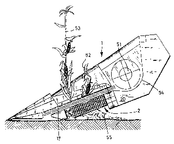
Figure 1 shows a side view of a picking attachment
illustrating the working method,
Figure 2 shows a partial section and a front elev-
ation illustrating the working method,
Figure 3 shows on a larger scale a section through
a first embodiment,
Figure 4 shows a section on the line A - A in
Figure 1,
Figure 5 shows a section through a second embodi-
went,
Figure 6 shows a section through a third embodiment,
Figure 7 shows a section through a .fourth embodiment
and
Figure 8 shows a section through a fifth embodiment
of the invention.
In Figures 1 and 2 a picking attachment 1 is shown,
wherein for each row of plants a respective pull-in rotor
2 is provided which is directed in the direction of
travel and which on its right-hand side is bounded by a
partial covering 14. This partial covering 14 serves as
a back support for the pulling-down and cutting of the
corn plants 52 and 53, the corn plant 53 being shown
still in the upright position while the corn plant 52 has
already been partly pulled down and the corncob shown is
lying against the breaking edge of a picking gap 15. In
the bottom region of the partial covering there are
provided cutting tools 10 which, in the exemplary embodi-
ment illustrated in Figure 2, are in the form of cutting

- 4 -
disks of a separate cutting roller. The cutting disks
engage in slits in the pull-in rotor 2. As the corn
stalks are guided past these cutting tools a chopping
process is carried out. The corncobs are stripped off in
the picking gap 15 by means of two picking plates 16.
The corncob is then carried by means of pull-in chains,
for example 17, into a trough 54, in which the corncobs
are further transported by a transverse conveyor screw
51.
The chopped material produced by the cutting tools
is shown at 55 in Figures 1 and 2.
A first embodiment of the picking attachment accord-
ing to the invention is shown on a larger scale in
Figures 3 and 4. In Figure 3 frame members 19 and 20 can
be seen, the frame member 19 carrying a partial covering
14 in the bottom region of which is arranged a cutting
roller 22, which is formed by a multiplicity of cutting
3
disks 11. These cutting disks 11 are arranged on a
carrier shaft 12, and the cutting disks 11 are preferably
fastened on the rotatably mounted carrier shaft 12. The
direction of rotation of the cutting roller 22, and also
that of the pull-in rotor 2, are indicated by the arrows
shown in the drawing. It can clearly be seen that the
carrier shaft 12, viewed from the picking gap 15, is
situated lower than the axis of the pull-a.n rotor 2. The
effect is thereby achieved that during the cutting of the
plant the latter is held securely and firmly by the pull-
in device (pull-in roller 2 and partial covering 14). At
the bottom the arrangement is closed by a cover 21. In
the exemplary embodiment shown in Figure 3, six blades 3,
4, 5, 6, 7 and 8, also referred to as tearing edges, are
arranged on the pull-in rotor 2, these blades 3 to 8
being twisted spirally over the entire length of the
pull-in rotor in a manner known per se, in order to
ensure a continuous torque pattern. Slits 9, into which
the cutting disks 11 project, are provided a.n the blades
3 to 8.
On the frame members 19 and 20 picking plates 16 are
provided in the top region and bound a picking gap 15,

2~~6~~I
-5_
which in the boundary region is provided with a breaking
edge. Above the picking plates 16 are provided pull-in
chains 17 and 18, of which only the rotary rotors can be
seen in the schematic representation shown in Figure 3.
The picking plates 16 may be hydraulically adjustable.
As is particularly clearly shown in Figure 4, the
cutting disks 11 of the cutting roller 22 engage in
corresponding slits 9 in the blades 4 to 8 and also
partially in circumferential slits which are likewise
provided on the core of the pull-in rotor 2.
In the representation shown in Figure 5 the partial
covering 14 can likewise be seen but, in contrast to
Figure 3, a mating rotor 23 is provided. The actual
pull- in rotor 2 has only f ive blades 3 , 4 , 5 , 6 and 7
and the mating rotor 23 has three blades, these two
rotors being controlled such that the blades engage in
one another intermittently, that is to say the ends of
the blades of the mating rotor 23 engage in the envelop-
ing circle of the pull-in rotor 2.
The blades of the pull-in rotor 2 and the blades of
the mating rotor 3 are provided with slits in which the
cutting disks 11 of the cutting roller 22, which is
mounted in an appropriately low position, engage.
In the embodiment shown in Figure 6, although a
mating roller 23 is likewise provided, the blades of the
mating roller 23 are so short that they do not engage in
the enveloping circle of the blades of the pull-in rotor
2, and the cutting disks 11 also do not engage in
corresponding slits in the blades of the mating rotor 23.
In the embodiment shown in Figure 7 the partial
covering is not provided, and in this embodiment too the
possible directions of rotation of the rotating compo-
nents are indicated by arrows.
Finally, in the embodiment shown in Figure 8 two
pull-in rotors 2 and 2a are provided, cooperating with a
cutting roller 22.
In connection with the embodiments described above
it should be pointed out that the cutting rollers 22 can
be freely rotatable~ either a.n such a manner that the

2 ~. 4 6 3'~.~
- 6 -
individual cutting disks 11 can rotate freely on a
central carrier shaft 12 of the cutting roller 22, or
such that the cutting disks 11 are mounted fast on the
carrier shaft 12 and the latter now rotates together with
the cutting disks 11.
The cutting roller 22 or the cutting disks 11 can be
freely rotatable or they may be driven in the opposite
direction of rotation to that of the pull-in rotor 2, or
they may be driven in the same direction of rotation as
the pull-in rotor 2. All these abovementioned possibil-
ities are practicable within the scope of the proposal
according to the invention.
However, all the embodiments described above have in
common the fact that the cutting roller 22 forms an
independent, separate cutting roller, and thus is not a
development of the pull-in rotor 2, and that the cutting
roller 22 is arranged, relative to the pull-in rotor 2,
such that the cut starts only when the plant stalk is
securely held by the pull-in device, that is to say can
be pulled further down even after the cut has been made.

Dessin représentatif
Une figure unique qui représente un dessin illustrant l'invention.
États administratifs

2024-08-01 : Dans le cadre de la transition vers les Brevets de nouvelle génération (BNG), la base de données sur les brevets canadiens (BDBC) contient désormais un Historique d'événement plus détaillé, qui reproduit le Journal des événements de notre nouvelle solution interne.

Veuillez noter que les événements débutant par « Inactive : » se réfèrent à des événements qui ne sont plus utilisés dans notre nouvelle solution interne.

Pour une meilleure compréhension de l'état de la demande ou brevet qui figure sur cette page, la rubrique Mise en garde , et les descriptions de Brevet , Historique d'événement , Taxes périodiques et Historique des paiements devraient être consultées.

Historique d'événement

Description Date
Inactive : Périmé (brevet - nouvelle loi) 2014-09-28
Inactive : TME en retard traitée 2007-10-15
Lettre envoyée 2007-09-28
Accordé par délivrance 2003-10-07
Inactive : Page couverture publiée 2003-10-06
Exigences de modification après acceptation - jugée conforme 2003-08-05
Lettre envoyée 2003-08-05
Préoctroi 2003-07-17
Inactive : Taxe finale reçue 2003-07-17
Inactive : Taxe de modif. après accept. traitée 2003-07-16
Modification après acceptation reçue 2003-07-16
Un avis d'acceptation est envoyé 2003-05-05
Lettre envoyée 2003-05-05
Inactive : Approuvée aux fins d'acceptation (AFA) 2003-04-16
Lettre envoyée 2001-10-25
Inactive : Grandeur de l'entité changée 2001-10-24
Exigences de rétablissement - réputé conforme pour tous les motifs d'abandon 2001-10-11
Réputée abandonnée - omission de répondre à un avis sur les taxes pour le maintien en état 2001-09-28
Inactive : Grandeur de l'entité changée 2001-07-16
Inactive : Renseign. sur l'état - Complets dès date d'ent. journ. 2001-06-06
Lettre envoyée 2001-06-06
Inactive : Dem. traitée sur TS dès date d'ent. journal 2001-06-06
Modification reçue - modification volontaire 2001-05-15
Toutes les exigences pour l'examen - jugée conforme 2001-05-15
Exigences pour une requête d'examen - jugée conforme 2001-05-15
Demande publiée (accessible au public) 1995-07-06

Historique d'abandonnement

Date d'abandonnement Raison Date de rétablissement
2001-09-28

Taxes périodiques

Le dernier paiement a été reçu le 2003-07-21

Avis : Si le paiement en totalité n'a pas été reçu au plus tard à la date indiquée, une taxe supplémentaire peut être imposée, soit une des taxes suivantes :

  • taxe de rétablissement ;
  • taxe pour paiement en souffrance ; ou
  • taxe additionnelle pour le renversement d'une péremption réputée.

Les taxes sur les brevets sont ajustées au 1er janvier de chaque année. Les montants ci-dessus sont les montants actuels s'ils sont reçus au plus tard le 31 décembre de l'année en cours.
Veuillez vous référer à la page web des taxes sur les brevets de l'OPIC pour voir tous les montants actuels des taxes.

Historique des taxes

Type de taxes Anniversaire Échéance Date payée
TM (demande, 3e anniv.) - générale 03 1997-09-29 1997-09-22
TM (demande, 4e anniv.) - générale 04 1998-09-28 1998-09-17
TM (demande, 5e anniv.) - générale 05 1999-09-28 1999-08-10
TM (demande, 6e anniv.) - générale 06 2000-09-28 2000-09-06
Requête d'examen - générale 2001-05-15
TM (demande, 7e anniv.) - générale 07 2001-09-28 2001-06-29
Rétablissement 2001-10-11
TM (demande, 8e anniv.) - générale 08 2002-09-30 2002-08-08
2003-07-16
Taxe finale - générale 2003-07-17
TM (demande, 9e anniv.) - générale 09 2003-09-29 2003-07-21
TM (brevet, 10e anniv.) - générale 2004-09-28 2004-09-14
TM (brevet, 11e anniv.) - générale 2005-09-28 2005-09-08
TM (brevet, 12e anniv.) - générale 2006-09-28 2006-09-06
TM (brevet, 13e anniv.) - générale 2007-09-28 2007-10-15
Annulation de la péremption réputée 2007-09-28 2007-10-15
TM (brevet, 14e anniv.) - générale 2008-09-29 2008-09-15
TM (brevet, 15e anniv.) - générale 2009-09-28 2009-09-14
TM (brevet, 16e anniv.) - générale 2010-09-28 2010-09-14
TM (brevet, 17e anniv.) - générale 2011-09-28 2011-09-15
TM (brevet, 18e anniv.) - générale 2012-09-28 2012-09-18
TM (brevet, 19e anniv.) - générale 2013-09-30 2013-09-18
Titulaires au dossier

Les titulaires actuels et antérieures au dossier sont affichés en ordre alphabétique.

Titulaires actuels au dossier
CARL GERINGHOFF GMBH & CO. KG
Titulaires antérieures au dossier
GEORG KRAßORT
LUDGER WIEGERT
Les propriétaires antérieurs qui ne figurent pas dans la liste des « Propriétaires au dossier » apparaîtront dans d'autres documents au dossier.
Documents

Pour visionner les fichiers sélectionnés, entrer le code reCAPTCHA :


Pour visualiser une image, cliquer sur un lien dans la colonne description du document. Pour télécharger l'image (les images), cliquer l'une ou plusieurs cases à cocher dans la première colonne et ensuite cliquer sur le bouton "Télécharger sélection en format PDF (archive Zip)" ou le bouton "Télécharger sélection (en un fichier PDF fusionné)".

Liste des documents de brevet publiés et non publiés sur la BDBC .

Si vous avez des difficultés à accéder au contenu, veuillez communiquer avec le Centre de services à la clientèle au 1-866-997-1936, ou envoyer un courriel au Centre de service à la clientèle de l'OPIC.


Description du
Document 
Date
(aaaa-mm-jj) 
Nombre de pages   Taille de l'image (Ko) 
Dessin représentatif 1999-05-26 1 17
Dessin représentatif 2003-04-15 1 19
Description 2003-07-15 6 280
Revendications 2003-07-15 2 75
Abrégé 2003-09-03 1 10
Abrégé 1995-06-27 1 10
Description 1995-06-27 6 271
Revendications 1995-06-27 2 70
Dessins 1995-06-27 4 138
Rappel - requête d'examen 2001-05-28 1 117
Accusé de réception de la requête d'examen 2001-06-05 1 179
Courtoisie - Lettre d'abandon (taxe de maintien en état) 2001-10-24 1 183
Avis de retablissement 2001-10-24 1 171
Avis du commissaire - Demande jugée acceptable 2003-05-04 1 160
Quittance d'un paiement en retard 2007-10-29 1 164
Avis concernant la taxe de maintien 2007-10-29 1 171
PCT 1995-04-03 24 819
Correspondance 2001-06-28 1 23
Correspondance 2003-07-16 1 34
Taxes 2003-07-20 1 34
Taxes 1999-08-30 1 38
Taxes 2001-06-28 1 41
Taxes 2001-10-10 2 58
Taxes 1996-08-21 1 58
Taxes 1997-01-15 2 58