Sélection de la langue

Search

Sommaire du brevet 2148937 

Énoncé de désistement de responsabilité concernant l'information provenant de tiers

Une partie des informations de ce site Web a été fournie par des sources externes. Le gouvernement du Canada n'assume aucune responsabilité concernant la précision, l'actualité ou la fiabilité des informations fournies par les sources externes. Les utilisateurs qui désirent employer cette information devraient consulter directement la source des informations. Le contenu fourni par les sources externes n'est pas assujetti aux exigences sur les langues officielles, la protection des renseignements personnels et l'accessibilité.

Disponibilité de l'Abrégé et des Revendications

L'apparition de différences dans le texte et l'image des Revendications et de l'Abrégé dépend du moment auquel le document est publié. Les textes des Revendications et de l'Abrégé sont affichés :

  • lorsque la demande peut être examinée par le public;
  • lorsque le brevet est émis (délivrance).
(12) Brevet: (11) CA 2148937
(54) Titre français: ELEMENT DE JOINT DE DILATATION
(54) Titre anglais: DILITATION JOINT ELEMENT
Statut: Durée expirée - au-delà du délai suivant l'octroi
Données bibliographiques
(51) Classification internationale des brevets (CIB):
  • E01D 19/06 (2006.01)
(72) Inventeurs :
  • ALMSTROM, OLOF (Suède)
(73) Titulaires :
  • TREMCO, INCORPORATED
  • INTERMERC KB
(71) Demandeurs :
  • TREMCO, INCORPORATED (Etats-Unis d'Amérique)
  • INTERMERC KB (Suède)
(74) Agent: SMART & BIGGAR LP
(74) Co-agent:
(45) Délivré: 2004-09-14
(86) Date de dépôt PCT: 1993-11-09
(87) Mise à la disponibilité du public: 1994-05-26
Requête d'examen: 2000-10-24
Licence disponible: S.O.
Cédé au domaine public: S.O.
(25) Langue des documents déposés: Anglais

Traité de coopération en matière de brevets (PCT): Oui
(86) Numéro de la demande PCT: PCT/SE1993/000948
(87) Numéro de publication internationale PCT: SE1993000948
(85) Entrée nationale: 1995-05-08

(30) Données de priorité de la demande:
Numéro de la demande Pays / territoire Date
9203355-4 (Suède) 1992-11-10

Abrégés

Abrégé anglais


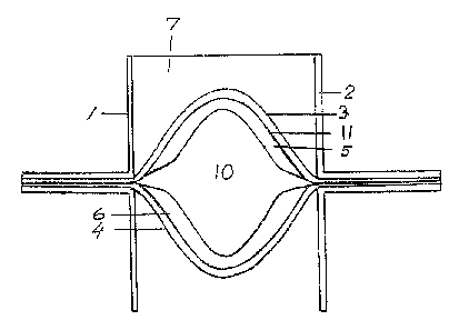
To avoid leakage in concrete structures with dilatation joints and to prevent
dirt from accumulating in the joints there has
been developed a dilatation joint element which is easy to mount, reliable and
essentially maintenance-free. The dilatation joint
element according to the invention is comprised of opposed, longitudinal angle
elements (1, 2) interconnected in pairs and made
of metal with interposed jointing compound (7), reinforcement bands (3, 4) and
rubber elements (5, 6). With curved band sections
and rubber elements between the angle elements and a curved jointing compound
section which is attached to the upper band
section there is provided a supporting, power-compensating and power-
distributing function when the joint is subjected to load, both
at compression, expansion and shearing, providing a tight, reliable and
loadable joint with good fatigue strength.

Revendications

Note : Les revendications sont présentées dans la langue officielle dans laquelle elles ont été soumises.


6
CLAIMS:
1. A dilatation joint element for joining structural members, such as for
joining roadway sections in bridges of cement concrete including a jointing
compound section connected between mounting elements and carried by a
reinforcement band supported by a yielding means, where the reinforcement
band and the yielding means together form a curved shape acting against the
jointing compound section, characterized in that the yielding means is
comprised of an upper upwardly oriented part of curved shape and a lower
downwardly oriented part of curved shape together forming a closed shape with
an open centre and in that the closed shape is surrounded by an upper and a
lower curved reinforcement band which are provided between the mounting
elements.
2. A dilatation joint element according to claim 1, wherein the yielding
means is comprised of a plurality of interacting curved upwardly and
downwardly oriented shaped parts together forming an essentially closed shape
with an open centre and that the closed shape is surrounded by an upper and a
lower reinforcement band inserted between the mounting elements.
3. A dilatation joint element according to claim 1 or 2, wherein the jointing
compound section is connected with upper portions of the mounting elements
and the curved upper band.
4. A dilatation joint element according to claim 1 or 2, wherein the mounting
elements are arranged in pairs opposite each other and with vertical upper and
lower portions.
5. A dilatation joint element according to claim 1 or 2, wherein the mounting
elements have horizontal portions which are provided with holes.
6. A dilatation joint element according to claim 2, wherein the interacting
shaped parts are comprised of two curved rubber profiles with a narrow centre
portion and wide end portions, which rubber profiles are oriented outwardly
from
one another.

Description

Note : Les descriptions sont présentées dans la langue officielle dans laquelle elles ont été soumises.

,l~O 94111579 214 ~ ~ 3'~ PGT/sE93/a094~
DILATATION'JOINT ELEMENT 1
DRSCRIFTION
Techn,ic~,~ f 'old
The present invention relates to a dilatation joint
element far forming a surface joint between two structural
members of, for example, cement concrete for use in joining,
' for example, structural members such as roadway sections in
bridges and parking garages.
;prior art
The reason why dilatation joints are required in
cement concrete structures is that is is desired to avoid
detrimental crack formation in finished structural members.
Tn cement concrete internal stresses may arise which, When
they become too intense, will gradually cause the concrete
.
i
to cxack. Hy providing openings between structural members,
for example; between concrete blocks, crack formation will
be located at the openings. Therefore, ~o called dilatation
openings are provided between the blocks in a concrete
structure, which dilata'~ion apenings are of ten joined and
cov~red by some kind of sealing joint structure.
The joints may be of the butt type or may be
flexible, depending on field of application. Butt joints, or
working joints, are utilized to facilitate the casting
process: Flexible joints, ar dilatation joints, are utilized
to minimize detrimental crack formation.
Cemea~t concret~ is a changeable material. When
losing water, the conere'~e cohtracts and it is also affected
by variations ~.n temperature which in our Swedish climate
may~imply ~Gon~s~:de,rabhe ;temperature di:ffer~nces:. Further; so
30- called creep occurs; the extent of which depends on the load
applied to the concrete over a certain period of time.
Linear expansion i~ often related to a fixed coefficient
defined by the material itself. The movement of the concrete
is thus influenced by a ~aumber of factors which together
give a total movement of a structural member of concrete, .
which again may affect the entire structure of which the
structural member forms part. -

fVVU 94/115'79 PCf/S1E93/00948 . '~'~,
~~~93°~
2
Besides absorbing said movements, the dilatation
joint should be sealing and should transmit forces between
structural members such as concrete blocks. Sealing is
required for preventing water containing, for instance, salt
and other substances detrimental to the concrete from pene-
trating and leaching the concrete and from damaging the
reinforcements, if any. Should water leakage occur in a
joint, water which has become alcalic through contact with
the concrete could damage underlying materials, for instance
in a parking garage, and cause damage to the paint of cars.
Further, infiltrating water could cause frost erosion and
crack formation. Tn order to be durable, a joint must be
tight and must be able to withstand mechanical influence of
various kinds as well as considerable temperature
differences.
There are previously known a variety of joint
structures for joining dilatation openings, in which either
some kind of jointing compound or a prefacricated dilatation
joint is used.
,~,~n~n.~r~' of the invention
To avoid leakage in concrete structures with
~,
dilatation joints and to prevent dirt from accumulating in
the joints, a dilatation joint element has been developed
z5 'a~ich is easy to mount, reliable and essentially main--
tenance-free. With a horizontal, planar upper surface there
will be no accumulation of dirt which would make the joint
butt, and the use of a snow plough is made possible. The
dilatation joi;~pt~element~according to the invention consists
30 of opposed, longitudinal angle elements interconnected in
pairs and made of metal with interposed jointing compound,
reinforcement bands and rubber elements. The dilatation
'joint is secured between concrete blocks by means of
casting. The jointing compound is arranged to be connected
35 with the upper vertical angle elements. Reinforcement bands
ara attached between the angle elements interconnected in
pairs, surrounding one or more rubber elements between the

~ W(~ 94/ 1 ! 579 _ ~ I ~ 9 3 '~
FCT/SE93/00948
3
opposed angle eleanents interconnected in pairs, the upper
band being connected with the jointing compound between the
angle elements. With this type of structure there is
provided essentially curved band sections between the angle
elements interconnected in pairs, as well as a curved join-
ting compound section which is attached to the upper band
section. With rubber elements (rubber fenders) disposed
opposite each other in pairs between the reinforcement bands
there is provided a supporting, power-compensating and
power-distributing function when the joint is subjected to
load, both at compression, expansion and shearing= which
gives a tight, reliable and loadable joint with good fatigue
strength.
~~,~ ~ on of the d~~gs
Figure 1 is a cross sectional view of a dilatation
joint according to the invention;
Figure 2 i.s a cross sectional view showing the
dilatation joint
in Figure 1 mounted
between two ~oncre~e
Zp elements;
Figure 3 is a cross sectional view of the dila-
tat.ion joint
under compression;
Figure 4 is a cross sectional view of the dila-
tation joint in expansion;
Figure 5 is ~ cross sectional view of the dila-
tation joint iv shearing;
Figure 6 is a cross sectional view of the dila-
tation joint mounted
in an angled
position, and
,, Figu~z~e ~' i's;ia ~ cross sectional view showing a
3a suitable rubber fender formed as a yielding eleanent.
lDe~ tion of a~ embodiment
Tn figure 2 there
is shown a dilatation
joint
mounted between two structure elements, such as two~cement
- 35 concrete blocks fo,r a bridge deck. The dilatation joint is
comprised of angle
elements 1, 2
of, for instance,
light
petal or steel ( 3fl x 30 x 1 , 5 mm) arranged in pairs _opposite

CA 02148937 2003-11-18
4
each other. An upper and a lower reinforcement band 3, 4 are
mounted between the angle elements 1, 2 arranged in pairs
opposite each other and are disposed such as to limit an
inner, curved space 10 which can accomodate a tubular ele-
ment or two or more interacting flexibly yielding elements
5, 6 of rubber, such as rubber fenders made of EPDM rubber
with a hardness of 70° Shore. The material of the reinforce-
ment bands 3, 4 may be laminated, synthetic fibre reinforced
polymerized PVC, such as Sikaplan~ PVC 12 BDWT/15 VDWT. Two
rubber fenders 5, 6 acting against one another are pre-
ferably used, which are curved and supporting relative to
the upper and lower bands. Between the upper vertical
portions of the angle elements and the upper curved band
there is interposed a jointing compound 7 of a hardness of,
for example, 35° Shore. The jointing compound material may
be a self-levelling polyurethane jointing compound, such as
Sikaflex~35 SL.
The outer ends of the angle elements arranged in
pairs opposite each other are mounted in recesses in the
concrete blocks 9 by means of an epoxy cement 8, such as
Sikadur~. Optionally, the angle elements may be attached to
the concrete blocks by means of screws, however, in order to
avoid crack formation it is preferred to provide holes in
the angle elements which during attachment are filled with
epoxy cement so as to form an additional attachment by means
of the epoxy cement in the recess. Between reinforcement
bands and rubber fenders there may be arranged an adhesive
11 such as flexible polyurethane jointing compound, for
instance, Sikaflex-11FC, and optionally a plastic film
between reinforcement bands and jointing compound
With said dilatation joint structure there is pro-
vided a jointing compound acting with reinforcement bands
and rubber fenders for the best possible connection,
carrying capacity, tightness, and flexibility with decreased
risk of ruptures and crack formation. The structure permits
shearing and essentially permanent bending of the joint with
or without adaption of the gap width. Seen in cross section,

..,~ W~ 94/11579 _ ~ ~. 4 ~ 9 3 "~ PGT/SE93/00948
the jointing compound, the reinforcement band and the rubber
fenders together form a structural member which during
expansion, see Figure 4, with weakening in the centre and
increasing torsional stress, is able to withstand this by
5 retaining its mounting height and by increased resistance
from the rubber fenders compressed by the bands. At com-
pression, see Figure 3, the laterally compressed rubber
fenders together with the reinforcement bands will control
deformation of the jointing compound and cause bulging of
the same. In the case of shearing and irregular dilatation,
see Figure 5, the interacting elements of the dilatation
joint may together provide a flexibility at essentially
maintained carrying capacity. In the case of angular defor-
mation only, see Figure 6, the dilatation joint maybe
adapted by mounting it in a curved or angled position and by
aelapting the jointing compound filling accordingly. Figure 7
shows in cross section an example of a suitable rubber
fender with ~ narrow centre portion and wide end portions
i
for good supporting effect during expansion.
~0 The dilatata.on joints may be manufactured in diffe
rent lengths so that they can be mounted without
lengthPn~.ng. xf dilatation joint elements are to be
lengthened, the end portions may be formed as male and
r
female parts with extended rubber fenders at one end and
shortened rubber fenders at the other end. In the case of
lengthening, the ends will then be inserted into each other
and an adhesive band is attached over the reinforcement band
ends, and jointing compound is then filled between the
~rertic~l -poztaons i of the angle elements . ;With this kind ~of
dilatation joint it is also possible to join several ele-
ments in a T~shape or cruciform shape by means of T-shaped
or cruciform connection elements, which are arranged to be
connected to the respective ends of the dilatation joint
elements. By selecting softer or harder jointing compound
and/~r wea~Cer or stronger rubber fenders, the dilatation
joint may be adapted to be either softer or harder, as
required._Instead of rubber fenders it is possible to insert
rubber hoses or a cylindrical rim of, for instance, neoprene.

Dessin représentatif
Une figure unique qui représente un dessin illustrant l'invention.
États administratifs

2024-08-01 : Dans le cadre de la transition vers les Brevets de nouvelle génération (BNG), la base de données sur les brevets canadiens (BDBC) contient désormais un Historique d'événement plus détaillé, qui reproduit le Journal des événements de notre nouvelle solution interne.

Veuillez noter que les événements débutant par « Inactive : » se réfèrent à des événements qui ne sont plus utilisés dans notre nouvelle solution interne.

Pour une meilleure compréhension de l'état de la demande ou brevet qui figure sur cette page, la rubrique Mise en garde , et les descriptions de Brevet , Historique d'événement , Taxes périodiques et Historique des paiements devraient être consultées.

Historique d'événement

Description Date
Inactive : Périmé (brevet - nouvelle loi) 2013-11-09
Inactive : Lettre officielle 2005-05-18
Accordé par délivrance 2004-09-14
Inactive : Page couverture publiée 2004-09-13
Préoctroi 2004-06-23
Inactive : Taxe finale reçue 2004-06-23
Lettre envoyée 2004-02-05
Un avis d'acceptation est envoyé 2004-01-14
Lettre envoyée 2004-01-14
Un avis d'acceptation est envoyé 2004-01-14
Inactive : Correspondance - Transfert 2004-01-08
Inactive : Approuvée aux fins d'acceptation (AFA) 2004-01-06
Inactive : Lettre officielle 2003-12-08
Lettre envoyée 2003-11-27
Exigences de rétablissement - réputé conforme pour tous les motifs d'abandon 2003-11-18
Modification reçue - modification volontaire 2003-11-18
Réputée abandonnée - omission de répondre à un avis sur les taxes pour le maintien en état 2003-11-10
Inactive : Transfert individuel 2003-10-08
Inactive : Dem. de l'examinateur par.30(2) Règles 2003-05-28
Lettre envoyée 2002-04-23
Inactive : Transfert individuel 2002-02-28
Lettre envoyée 2000-12-06
Inactive : Renseign. sur l'état - Complets dès date d'ent. journ. 2000-12-05
Inactive : Dem. traitée sur TS dès date d'ent. journal 2000-12-05
Exigences pour une requête d'examen - jugée conforme 2000-10-24
Toutes les exigences pour l'examen - jugée conforme 2000-10-24
Demande publiée (accessible au public) 1994-05-26

Historique d'abandonnement

Date d'abandonnement Raison Date de rétablissement
2003-11-10

Taxes périodiques

Le dernier paiement a été reçu le 2004-08-16

Avis : Si le paiement en totalité n'a pas été reçu au plus tard à la date indiquée, une taxe supplémentaire peut être imposée, soit une des taxes suivantes :

  • taxe de rétablissement ;
  • taxe pour paiement en souffrance ; ou
  • taxe additionnelle pour le renversement d'une péremption réputée.

Les taxes sur les brevets sont ajustées au 1er janvier de chaque année. Les montants ci-dessus sont les montants actuels s'ils sont reçus au plus tard le 31 décembre de l'année en cours.
Veuillez vous référer à la page web des taxes sur les brevets de l'OPIC pour voir tous les montants actuels des taxes.

Historique des taxes

Type de taxes Anniversaire Échéance Date payée
TM (demande, 4e anniv.) - petite 04 1997-11-10 1997-10-24
TM (demande, 5e anniv.) - petite 05 1998-11-09 1998-10-13
TM (demande, 6e anniv.) - petite 06 1999-11-09 1999-10-12
TM (demande, 7e anniv.) - petite 07 2000-11-09 2000-10-18
Requête d'examen - petite 2000-10-24
TM (demande, 8e anniv.) - petite 08 2001-11-09 2001-10-15
Enregistrement d'un document 2002-02-28
TM (demande, 9e anniv.) - petite 09 2002-11-11 2002-10-24
Enregistrement d'un document 2003-10-08
Rétablissement 2003-11-18
TM (demande, 10e anniv.) - petite 10 2003-11-10 2003-11-18
Taxe finale - petite 2004-06-23
TM (demande, 11e anniv.) - petite 11 2004-11-09 2004-08-16
2005-10-19
TM (brevet, 12e anniv.) - petite 2005-11-09 2005-10-19
TM (brevet, 13e anniv.) - petite 2006-11-09 2006-10-17
2006-10-17
TM (brevet, 14e anniv.) - générale 2007-11-09 2007-10-17
TM (brevet, 15e anniv.) - générale 2008-11-10 2008-10-17
TM (brevet, 16e anniv.) - générale 2009-11-09 2009-10-20
TM (brevet, 17e anniv.) - générale 2010-11-09 2010-10-18
TM (brevet, 18e anniv.) - générale 2011-11-09 2011-10-17
TM (brevet, 19e anniv.) - générale 2012-11-09 2012-10-17
Titulaires au dossier

Les titulaires actuels et antérieures au dossier sont affichés en ordre alphabétique.

Titulaires actuels au dossier
TREMCO, INCORPORATED
INTERMERC KB
Titulaires antérieures au dossier
OLOF ALMSTROM
Les propriétaires antérieurs qui ne figurent pas dans la liste des « Propriétaires au dossier » apparaîtront dans d'autres documents au dossier.
Documents

Pour visionner les fichiers sélectionnés, entrer le code reCAPTCHA :


Pour visualiser une image, cliquer sur un lien dans la colonne description du document (Temporairement non-disponible). Pour télécharger l'image (les images), cliquer l'une ou plusieurs cases à cocher dans la première colonne et ensuite cliquer sur le bouton "Télécharger sélection en format PDF (archive Zip)" ou le bouton "Télécharger sélection (en un fichier PDF fusionné)".

Liste des documents de brevet publiés et non publiés sur la BDBC .

Si vous avez des difficultés à accéder au contenu, veuillez communiquer avec le Centre de services à la clientèle au 1-866-997-1936, ou envoyer un courriel au Centre de service à la clientèle de l'OPIC.

({010=Tous les documents, 020=Au moment du dépôt, 030=Au moment de la mise à la disponibilité du public, 040=À la délivrance, 050=Examen, 060=Correspondance reçue, 070=Divers, 080=Correspondance envoyée, 090=Paiement})


Description du
Document 
Date
(aaaa-mm-jj) 
Nombre de pages   Taille de l'image (Ko) 
Dessin représentatif 1994-04-15 1 9
Description 2003-11-17 5 346
Revendications 2003-11-17 1 45
Dessin représentatif 2004-01-05 1 9
Abrégé 1995-11-17 1 70
Revendications 1995-11-17 2 90
Description 1995-11-17 5 369
Dessins 1995-11-17 2 87
Rappel - requête d'examen 2000-07-10 1 115
Accusé de réception de la requête d'examen 2000-12-05 1 180
Courtoisie - Certificat d'enregistrement (document(s) connexe(s)) 2002-04-22 1 114
Courtoisie - Lettre d'abandon (taxe de maintien en état) 2003-11-26 1 177
Avis de retablissement 2003-11-26 1 167
Avis du commissaire - Demande jugée acceptable 2004-01-13 1 161
Courtoisie - Certificat d'enregistrement (document(s) connexe(s)) 2004-02-04 1 107
PCT 1995-05-07 8 300
Correspondance 2003-12-07 1 12
Taxes 2003-11-17 1 36
Taxes 1998-10-12 1 39
Taxes 2002-10-23 1 24
Taxes 2001-10-14 1 31
Taxes 1997-10-23 1 35
Taxes 1999-10-11 1 27
Taxes 2000-10-17 1 30
Correspondance 2004-06-22 1 31
Taxes 2004-08-15 1 32
Correspondance 2005-05-17 1 16
Correspondance 2005-06-22 1 34
Taxes 1996-10-28 1 29
Taxes 1995-10-29 1 29