Note : Les descriptions sont présentées dans la langue officielle dans laquelle elles ont été soumises.
2150808
SPECIFICATION
The invention involves a press tool, specifically
for joining tubular workpieces, having a wraparound ring
comprised of at least three hinged clamping components,
in which the press tool is open at at least one closing
point between two clamping components and has grips at
that position for a closing device by means of which the
clamping components can be brought together to form a
closed ring.
One known-in-the-art process for joining the ends of
tubular workpieces involves using tubular press fittings
that are ductile and are comprised of metal, preferably
of steel. The inside diameter of the fittings is greater
than the outside diameter of the pipe ends to be joined,
so that when the fittings are pressed together radially
in order to mount them on the surface of the pipe ends
they will become permanently deformed. These types of
pipe joints and the associated press fittings can be
found, for example, in DE-C1 187 870 and DE-C-40 12 504.
For the process of pressing the fittings together
radially, a wide range of press tools have been
developed. Because in the past this process has been
used primarily in the joining of smaller diameter pipe
ends, press tools having only two clamping components
have been developed (comp. DE-A-34 23 283). If greater
diameter reductions or insertion depths are required, for
example if the pipe joint will be required to withstand
greater internal pressures, it becomes necessary for the
~- 21S0808
press tool to contain more than two clamping components
to prevent the formation of lands on the outside, between
the surfaces of the clamping jaws, which would prevent
them from closing completely. Simply designed press
tools of this type can be found in EP-A-0 451 806. In
relation to this, the press tools illustrated in Figures
(7) and (8) are of particular interest, as they are
suited to the joining of pipe ends that are large or very
large in diameter.
These press tools contain a wraparound ring that is
open at one closing point and is comprised of hinged
clamping components, which are comprised of a clamping
bracket and clamping jaws that can be moved
circumferentially. This type of wraparound ring can be
positioned like a collar around the point that is to be
pressed, and then drawn together with the help of a
closing device. The closing device may be permanently
connected to the wraparound ring. If the wraparound ring
is intended and designed for pressing larger pipe
diameters, however, it is more advantageous in terms of
weight and handling to design the closing device as a
unit that is separate from the wraparound ring, which can
be attached to the wraparound ring in the area of the
closing point, after the ring has been positioned around
the press fitting; specifically it can be attached to
grips that are intended for this purpose and are fitted
to the closing device on both of the clamping components
that are adjacent to the closing point.
- 2150808
It would be desirable to expand the application of
such press tools to include even greater pipe diameters.
The wraparound ring then becomes so heavy, however, that
handling and safety problems result in placing it around
the pipe end or around the press fitting. It is thus the
object of the invention to design a press tool of the
type described in the beginning for which handling,
particularly for larger pipe diameters, is facilitated.
This object is attained in accordance with the
invention in that it includes at least one coupling
member by means of which the clamping components adjacent
to the closing point can be connected, with the coupling
member being designed so as to be flexible in the coupled
position in the closed direction.
Thus, in accordance with the basic premise of the
invention, after the wraparound ring has been placed
around the pipe end or the press fitting, it can be
temporarily secured, causing the open closing point to be
bridged over by a coupling member, which closes the
wraparound ring. The wraparound ring is then unable to
slide off, which eliminates the need to secure the
wraparound ring for the attachment of the closing device.
So that the drawing together of the clamping components
to form a closed wraparound ring in the coupled position
will not be hindered, or will not be significantly
hindered, the coupling member is designed in accordance
with the invention to be flexible in the closing
- 21S0808
direction, but to limit the flexibility of the clamping
components in the opening direction.
In a lighter dimensioned press tool, the entire
coupling member can be dimensioned such that the
wraparound ring remains able to rotate around the
workpiece. In heavily dimensioned press tools for larger
pipe diameters, however, it is preferable for the
coupling member to be dimensioned such that a peripheral
force is exerted on the wraparound ring that has been
placed around the workpiece with the coupling member in
the closed position, so that the wraparound ring is
fitted with a certain degree of initial tension to the
workpiece that is to be pressed, specifically the press
fitting, leaving the wraparound ring at least unable to
rotate on its own.
Several embodiments are possible for the design of
the coupling member. For instance, the coupling member
may contain a first coupling bracket that is hinged to
the first clamping component, and a second coupling
bracket that is connected to the other clamping
component, whereby both coupling brackets may be hinged
to one another, for example via a coupling pin that is
set into both coupling brackets. This type of coupling
member limits the flexibility of the clamping components
in the opening direction, but is able, during the
pressing process, to yield toward the outside with the
help of the closing device, without offering significant
resistance to the closing device.
2150808
To ensure a simple and convenient mounting, in other
words the bridging over of the closing point via the
coupling member, it is recommended in accordance with the
invention for the coupling pin in the above-mentioned
embodiment of the coupling member to contain a first pin
segment that is set into the first coupling bracket and a
second pin segment that can be set into the second
coupling bracket, with the axes of the pin segments being
displaced in relation to one another. The second pin
segment thus creates an eccentric. This design makes it
possible to insert the coupling pins even if no initial
tension is being exerted on the press fitting, by
rotating the coupling pins to exert a peripheral force.
To enable this, the length of the coupling brackets and
the extent of the displacement of the axes of the pin
segments in the coupling pins in relation to the
circumferential extension of the closing position must be
appropriately coordinated. To facilitate the rotation of
the coupling pin, it is connected to a lever. This is
intended to permit the coupling pin to be captively
directed into one of the coupling brackets.
A further feature of the invention provides for the
coupling brackets to be hinged via hinge pins to the
corresponding clamping components, and for recesses to be
included in the area of the hinge pins, behind which
closing elements of the closing device can catch. The
hinge pins in this exemplary thus also form the grips for
the closing device.
- 2150808
As an alternative to or in combination with the
above embodiment, at least one clamping device for the
purpose of mounting the wraparound ring on the inserted
workpiece can be attached to one side of the ring, in
which the clamping device(s), for example, may contain
clamping elements that are under spring tension. Thus,
following the temporary coupling of the wraparound ring
via the coupling member, these clamping devices are
positioned adjacent to the inserted workpiece, such that
the upcast workpiece is unable to slide off. This
facilitates the mounting process, particularly in the
case of perpendicular or diagonally laid pipework, and at
the same time serves in the axial safeguarding of the two
nested workpieces.
The press tool specified in the invention is not
limited to a design of the wraparound ring that contains
only one open closing point. Particularly if the press
tool is intended for the pressing of large diameter pipes
and is correspondingly dimensioned to accommodate them,
it can be advantageous for the wraparound ring to contain
more than one closing point and for each closing point to
contain a coupling member that is designed in accordance
with the invention. This design makes it possible to
assemble the wraparound ring from individual elements on
the spot, in other words in the area of the pipe ends
that are to be joined, or even in succession as the
wraparound ring is being placed around the pipe end. It
is also possible for the design to contain, between all
- 2150808
the clamping components, a closing point that can be
bridged over with a coupling member.
The constriction of the wraparound ring, and thereby
the pressing of the pipe end with the press fitting, can
occur in succession in such a way that the closing points
are drawn together, with the help of the closing device,
one after another. Another possibility, however, is for
one of the closing devices, the number of which
corresponds to the number of closing points, to be set in
position, and for the closing points to then be pulled
together synchronously.
This may also be achieved by connecting the clamping
components to one another outside of the closing point(s)
via removable hinge pins, as this will also allow the
wraparound ring to be conveniently assembled on location.
In addition, the clamping components may be connected via
adapters to which the adjacent clamping components are
hinged via hinge pins, with at least one of the hinge
pins per adapter being removable.
In a design that is known-in-the-art, each of the
clamping components is comprised of a clamping jaw and a
clamping bracket in which each clamping jaw is positioned
in the clamping bracket such that it can move
circumferentially; in this design the coupling member(s)
are positioned adjacent to the clamping brackets, and the
clamping brackets are hinged to one another. The
coupling member(s) may, however, also be positioned
directly on the clamping jaws.
2150808
In the diagrams, the invention is illustrated in
greater detail with reference to one exemplary
embodiment. These diagrams show:
Figure (1) - the wraparound ring of a press tool in
an opened position;
Figure (2) - the wraparound ring in accordance with
Figure (1) in a closed position;
Figure (3) - a sectional view of the coupling member
of the wraparound ring in accordance with Figures (1) and
(2) as indicated by plane A-B, with the coupling member
in a loose position;
Figure (4) - the coupling member in the
representation in accordance with Figure (3), in a taut
posltion;
Figure (5) - the wraparound ring in accordance with
Figures (1) through (4) in its position following the
pressing process, and
Figure (6) - a wraparound ring with closing points
and coupling members between each clamping component.
In Figures (1), (2), and (5), a cross-section of a
pipe end (1) and a press fitting (2) that has been slid
onto the pipe end, with an annular ring (3) that contains
a conical nipple, are indicated by a dot-dashed line.
The pipe end (1) and press fitting (2) are to be pressed
using a press tool (4), of which only the wraparound ring
(5) is illustrated in Figures (1), (2), and (5).
The wraparound ring (5) in this exemplary embodiment
contains clamping components (6, 7, 8, 9, 10) that are
- 2150808
essentially identical in design, with each clamping
component (6, 7, 8, 9, 10) being comprised of an outer
clamping bracket (11, 12, 13, 14, 15) and an inner,
curved, clamping jaw (16, 17, 18, 19, 20). With one
exception, the clamping brackets are connected to one
another via adapters (21, 22, 23, 24), with the clamping
brackets (11, 12, 13, 14, 15) being hinged via hinge pins
(26, 27, 28, 29, 30, 31, 32, 33) to the adapters (21, 22,
23, 24).
In each case at least one hinge pin (26, 27, 28, 29,
30, 31, 32, 33) per adapter (21, 22, 23, 24) is designed
to be removable, so that the wraparound ring (5) can be
dismantled into individual clamping components (6, 7, 8,
9, 10) or can be assembled from these on the spot. The
clamping jaws (16, 17, 18, 19, 20) are positioned in the
clamping brackets (11, 12, 13, 14, 15) such that they can
shift circumferentially.
A clamping device (34, 35, 36, 37, 38) is attached
to each clamping bracket (11, 12, 13, 14, 15) and
contains a clamping piston (39, 40, 41, 42, 43) that is
directed radially toward the inside and is held under
spring tension. The clamping devices (34, 35, 36, 37,
38) also serve in the axial guidance of the clamping jaws
(16, 17, 18, 19, 20).
The hinge pins (29, 30) on the center clamping
bracket (13) support a jaw-shaped template (44) in the
form of a metal component containing a semi-circular
recess (45), in which the radius of the recess (45) is
- 2150808
such that the template (44) fits over the pipe end (1)
but not over the cylindrical portion of the press fitting
(2) that is adjacent to the annular ring (3). This
ensures that the wraparound ring (5) can be placed around
the combination of pipe end (1) and press fitting (2) in
only one, preferred way.
The lower clamping components (6, 10) have between
them, in the positions indicated in Figures (1) and (2),
a closing gap (46). In Figure (1) this gap is large
enough that the wraparound ring (5) can be placed over
the press fitting (2) and the pipe end (1). The free
ends of the clamping components (6, 10) that are adjacent
to the closing gap (46) contain hinge pins (47, 48), with
a coupling bracket (49, 50) being suspended from each
hinge pin (47, 48). The shape of the coupling brackets
(49, 50) and their connection to the hinge pins (47, 48)
are indicated specifically in the sectional illustration
in accordance with Figures (3) and (4).
The free ends of the coupling brackets (49, 50)
contain openings (51, 52). A coupling pin (53) is
inserted axially into the boring (51) in the coupling
bracket (49). This pin contains a first pin segment
(54), which extends through the boring (51). One end of
the first pin segment-(54) is connected to a hand lever
(55). At the other end of the first pin segment (54) is
a second pin segment (56), the axis of which is displaced
in relation to the first pin segment (54) by a degree of
- 21~0808
eccentricity (57). The second pin segment (56) fits into
the boring (52) in the other coupling bracket (50).
The coupling brackets (49, 50), together with the
coupling pins (53), form a coupling element for the
temporary connection of the ends of the wraparound ring
(5) prior to the actual pressing process. For this
purpose, the opened wraparound ring (5) is first placed
over the pipe end (1) and the press fitting (2), as is
indicated in Figure (1). When the wraparound ring (5) is
on the pipe end (1) or press fitting (2), the two lower
clamping components (6, 10) are swung toward one another
and on the pipe end (1), so that they assume the position
illustrated in Figure (2). The coupling brackets (49,
50) that then remain suspended, a position which is
indicated in Figure (2) by a dot-dashed line, are then
swung toward one another in the directions of arrows C
and D. The coupling pin (53) is then in a position in
which its second pin segment (56) does not protrude from
the boring (51), which is indicated in Figure (3) by the
dot-dashed line indicating the position of the hand lever
(55).
The horizontal sweep of the coupling brackets (49,
50) continues up to the position at which they overlap
and the borings (51, 52) merge. The coupling pin (53),
and thereby also the hand lever (55), are then in a
position in which the second pin segment (56) is shifted
toward the other coupling bracket (50), and can thus
easily be set into its boring (52) via the axial shifting
- 21~0808
of the coupling pin (53), and can thereby join the two
coupling brackets (49, 50). In this position, the
wraparound ring (5) still maintains a certain degree of
slack.
The hand lever (55) is then swung 180 from the
position indicated in Figure (2) by solid lines, into the
position indicated by a dot-dashed line, in the direction
of the arrow E. This causes the second pin segment (56)
to execute an eccentric motion and to shorten the
distance between the two hinge pins (47, 48) by double
the eccentricity (57). This is made clear in the
comparison of Figures (3) and (4), with Figure (4)
illustrating the swung position. This movement exerts a
peripheral force on the wraparound ring (5), which causes
the clamping jaws (16, 17, 18, 19, 20) to press with a
certain degree of radial tension on the press fitting
(2). The wraparound ring (5) then has a fit that cannot
be rotated or is at least very difficult to rotate. This
effect is enhanced by the clamping pistons (39, 40, 41,
42, 43), which then press against the pipe end (1) with
equal, radially directed tension, thus ensuring an axial
mounting between pipe end (1) and press fitting (2).
Now the actual pressing process can begin. In this
process, a closing device, which will not be described in
greater detail and is part of the press tool, is used, as
is known schematically from Figure (7) of EP-A-0 451 806.
This closing device contains two tong-shaped lever arms,
by means of which the closing device can be attached to
- 2150808
the hinge pins (47, 48). This causes them to extend
through spaces (58, 59) or (60, 61) and to be adjacent to
the outsides of the hinge pins (47, 48). The tong-shaped
lever arms are then brought together by means of a
hydraulic motor that is part of the closing device, so
that the hinge pins (47, 48) approach one another. The
result of this is that the wraparound ring (5) becomes
constricted, which causes the press fitting (2) and the
pipe end (1) to be radially compressed, whereby clamping
jaws (16, 17, 18, 19, 20) are automatically displaced
circumferentially, to the point at which the surfaces of
the clamping jaws (16, 17, 18, 19, 20) are touching. At
the same time, the coupling brackets (49, 50) yield
toward the outside, which keeps them from interfering
with the pressing process.
Following the conclusion of the pressing process,
the wraparound ring (5) assumes the position illustrated
in Figure (5). After the axial displacement of the
coupling pin (53), which causes the second pin segment
(56) to slip out of the boring (52), the wraparound ring
(5) can be removed and used for other pressing processes.
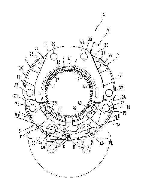
In Figure (6), a somewhat modified press tool (62)
from the above-specified embodiment is illustrated. This
design is basically the same as for the press tool (4)
illustrated in Figures (1) through (5), so that in Figure
(6), components that are identical to those in the press
tool in accordance with Figures (1) through (5) are
indicated by the same numbers. In the description of
-- 2150808
this modified press tool, reference is made to the
description of the first exemplary embodiment.
In contrast with the press tool (4), the wraparound
ring (63) of the press tool (62) illustrated in Figure
(6) has no clamping devices, and is instead equipped only
with guide plates (64, 65, 66, 67), located in the same
positions. Additionally, the clamping brackets (11, 12,
13, 14, 15) in this embodiment are connected not via
adapters, but via pairs of coupling brackets (68, 69) or
(70, 71) or (72, 73) or (74, 75), which are hinged to the
hinge pins (26, 27, 28, 29, 30, 31, 32, 33) and are
connected to one another via coupling pins (76, 77, 78,
79). The design of the coupling brackets (68, 69, 70,
71, 72, 73, 74, 75) and the coupling pins (76, 77, 78,
79) is identical to the design of the coupling brackets
(49, 50) and the coupling pin (53).
In Figure (6), the wraparound ring (63) is shown in
a position that is occupied by the wraparound ring (63)
following the pressing process, in which the surfaces of
the clamping jaws (16, 17, 18, 19, 20) are touching. The
wraparound ring (63) can be dismantled into the five
clamping components (7, 8, g, 10) by decoupling the pairs
of coupling brackets (68, 69) or (70, 71) or (72, 73) or
(74, 75). From this disassembled state it can in turn be
assembled on the spot, even in the process of being
mounted around a pipe end or press fitting, by coupling
the pairs of coupling brackets (68, 69) or (70, 71) or
(72, 73) or (74, 75), in a process that is similar to
2I50808
that associated with the pair of coupling brackets (49,
50) for the press tool (4) in accordance with Figures (1)
through (5). The result is a closed wraparound ring
(63), in which the pairs of coupling brackets (68, 69) or
(70, 71) or (72, 73) or (74, 75) assume an elongated
positioning, as is illustrated by the coupling bracket
(49, 50) in Figure (2).
The subsequently performed pressing process can
occur via two different methods. In one method, five
closing devices may be simultaneously attached to the
pairs of hinge pins (26, 27) or (28, 29) or (30, 31) or
(32, 33) or (49, 50), so that the distances between the
clamping jaws (16, 17, 18, 19, 20) in the synchronous
manipulation of the closing devices are simultaneously
shortened to the opposite unit. The second method
involves effecting the pressing process using only one
closing device, in which the closing device is attached
to the pairs of hinge pins (26, 27) or (28, 29) or (30,
31) or (32, 33) or (47, 48) one at a time, after which
these are drawn together until the positioning of all
clamping components (6, 7, 8, 9, 10) illustrated in
Figure (6) has been achieved.
16