Note : Les descriptions sont présentées dans la langue officielle dans laquelle elles ont été soumises.
2ls~l8o
SPECIFICATION
METHOD OF AND APPARATUS FOR DISASSEMBLING CAN
FOR MEASUREMENT OF CAN SEAM DIMENSIONS
TECHNICAL FIELD
The present invention relates to a method of and an
apparatus for disassembling the can-seamed region of a can
prior to inspection of dimensions of the can-seamed region.
RAC~GROUND ART
To use a metallic can as a container for a carbonated
drink such as beer, a beverage, or the like, the liquid is
filled in a can body, and an end is fitted in the end
opening of the can body. Then, as shown in FIG. 1 of the
accompanying drawings, the outer circumferential edge
region of an end 101 and the open end of a can body 102
are can-seamed, thereby closing the end opening of the can
body 102. Specifically, the open end of the can body 102
is seamed such that the end 101 covers the outer circum-
ferential edge of the end opening of the can body 102.
If the can seaming is not properly effected, then the
interior of the can body is not sealed, allowing the
carbon dioxide and the liquid to leak out. To prevent
such a problem, the can-seamed end is inspected in the
manufacturing process. The inspection is carried out by
- 21 S~l 80
-- 2
measuring supervisory dimensions which include, as shown
in FIG. 1, the width W and the thickness T of the seamed
region, the length CH of a folded portion (hereinafter
referred to as a "cover hook 101a") of the outer circum-
ferential edge of the end 101, the length BH of a folded
portion (hereinafter referred to as a "body hook 102a") of
the can body 102, and the length OL of a portion (herein-
after referred to as an overlapping portion") in which
the cover hook 101a and the body hook 102a overlap each
other and are folded, and comparing the measured supervi-
sory dimensions with predetermined reference values. To
measure these supervisory dimensions, the can-seamed
region is disassembled.
One conventional method of disassembling a seamed
region will be described below with reference to FIG. 1.
inwardly of the can-seamed region with cutting pliers or a
can opener. Then, the remaining portion of the end 101 is
forcibly pulled with cutting pliers or nippers, whereupon
the end 101 is torn off at a region indicated by the arrow
A, leaving the cover hook 101a. Thereafter, the outer
circumferential surface of the cover hook 101a is pressed
downwardly toward the bottom of the can body with cutting
pliers or the like until the cover hook 101a is disengaged
from the body hook 102a. When the cover hook 101a is
disengaged from the body hook 102a, the supervisory dimen-
sions including the length BH of the body hook 102a and
2ls~l8o
the length CH of the cover hook lOla are measured, and
used as supervisory data for the seaming process.
Since the above conventional disassembling method
relies on manual work with cutting pliers or the like to
disassemble the can-seamed region, portions whose
dimensions are to be measured tend to be damaged, e.g.,
the body hook and the cover hook tend to be deformed or
damaged when the end is removed, and the body hook tends
to be pressed when the cover hook is removed from the body
hook. The operator needs to be skilled enough to disas-
semble the can-seamed region without deforming those
portions whose dimensions are to be measured, and it takes
a long period of time to disassemble the can-seamed
region. Therefore, the portions whose dimensions are to
be measured may be deformed depending on the skill with
which the can-seamed region is disassembled, with the
result that accurate data may not be obtained.
It has been proposed to employ an X-ray inspecting
device for inspecting the can-seamed region of a can with
X-rays without disassembling the can-seamed region. The
X-ray inspecting device is, however, very large in scale
and requires a large investment for the installation of
the device. Therefore, the X-ray inspecting device is not
suitable for use in carrying out daily inspections on the
production site.
2l~sl8o
DISCLOSURE OF THE lNV~NlION
It is an object of the present invention to provide a
method of and an apparatus for simply disassembling the
can-seamed region of a can in a short period of time
without deforming portions whose dimensions are to be
measured, for measurement of dimensions of the can-seamed
region.
To achieve the above object, there is provided in
accordance with the present invention a method of disas-
sembling a can for measurement of can seam dimensions, the
can being composed of a can body and an end which are
coupled to each other by a can-seamed region having an
open end of the can body and an outer circumferential edge
region of the end, the can body having an end opening
closed by the end thereby sealing the interior of the can,
the method comprising the steps of holding the can by
gripping the end and a bottom of the can body, and cutting
the outer circumferential edge region of the end which
externally surrounds a folded portion of the can body in
the can-seamed region in a circumferential direction of
the can.
With the above disassembling method according to the
present invention, since the can is held by gripping the
end and the bottom of the can body, the can is prevented
from being deformed radially inwardly when the can-seamed
region is cut. Because the can-seamed region is cut by
21~51 ~o
severing the outer circumferential edge region of the end
which externally surrounds the folded portion of the can
body in the can-seamed region in the circumferential
direction of the can, the end and a cover hook can easily
be separated from each other. Therefore, the can can
easily be disassembled without deforming those portions of
the can which are to be measured.
According to the present invention, there is also
provided an apparatus for disassembling a can for measure-
ment of can seam dimensions, the can being composed of a
can body and an end which are coupled to each other by a
can-seamed region having an open end of the can body and
an outer circumferential edge region of the end, the can
body having an end opening closed by the end thereby
sealing the interior of the can, the apparatus comprising
can holding means for holding the can by gripping the end
of the can and a bottom of the can body, rotating means
for rotating the can about its own axis which is held by
the can holding means, and a cutter disposed so as to
orient a cutting blade toward the axis of the can for
cutting the outer circumferential edge region of the end
which externally surrounds a folded portion of the can
body in the can-seamed region in a circumferential direc-
tion of the can.
The can holding means may comprise a mechanism for
abutting against the end of the can, and a mechanism for
2ls5l8o
-- 6
abutting against the bottom of the can body, the
mechanisms being spaced from each other by an adjustable
distance.
The cutter may be movable in the radial direction of
the can which is held by the can holding means.
With the disassembling apparatus according to the
present invention, the can is held by the can holding
means which grips the end of the can and the bottom of the
can body, and the rotated about its own axis by the
rotating means. Then, the cutter with its cutting blade
directed perpendicularly to the axis of the can cuts the
can-seamed region of the can in the circumferential
direction of the can.
BRIEF DESCRIPTION OF THE DRAWINGS
FIG. 1 is a cross-sectional view of the can-seamed
region of a can;
FIG. 2 is a plan view of an apparatus for disassem-
bling a can for measurement of dimensions of the seamed
region of the can, according to a first embodiment of the
present invention;
FIG. 3 is a side elevational view of the apparatus
shown in FIG. 2;
FIG. 4 is a partial cross-sectional view, as viewed
from an air cylinder, of a cutter unit of the apparatus
shown in FIG. 2;
2ls~l8o
- 7 -
FIG. 5 is a circuit diagram of an air circuit of the
apparatus shown in FIG. 2;
FIG. 6 is a side elevational view of an apparatus for
disassembling a can for measurement of dimensions of the
seamed region of the can, according to a second embodiment
of the present invention;
FIG. 7 is a partial cross-sectional view, as viewed
from a first air cylinder, of a cutter unit of the appara-
tus shown in FIG. 6; and
FIG. 8 is a circuit diagram of an air circuit of the
apparatus shown in FIG. 6.
BEST MODE FOR CARRYING OUT THE lNv~NLlON
Embodiments of the present invention will be described
below with reference to the drawings.
(lst Embodiment)
FIG. 2 is a plan view of an apparatus for disassem-
bling a can for measurement of dimensions of the seamed
region of the can, according to a first embodiment of the
present invention, and FIG. 3 is a side elevational view
of the apparatus shown in FIG. 2.
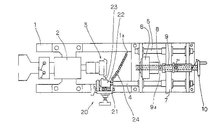
As shown in FIGS. 2 and 3, an air motor 2 is fixedly
mounted on a left-hand end (as shown) of a main frame 1
and has an output shaft to which there is secured a chuck
3 for fitting in an end attached to a can body. The drive
source for actuating the chuck 3 is not limited to the air
2~ 8o
motor 2, but may be an electric motor.
Two guide shafts 4, S are disposed on a right-hand
end (as shown) of the main frame 1 and extend parallel to
the output shaft of the air motor 2, which serves as a
rotating means. A cylinder support member 7 is slidably
supported on the two guide shafts 4, 5. Centrally through
the cylinder support member 7, there is threaded a cylin-
der moving screw shaft 8 which is rotatably supported on
the main frame 1 and has one end to which a pusher adjust-
ing handle 10 is fixed. When the pusher adjusting handle
10 is turned, the cylinder moving screw shaft 8 is rotated
about its own axis to move the cylinder support member 7
in the axial direction of the guide shafts 4, 5. The
cylinder support member 7 is thus axially movable to allow
a pusher 6 (described later) and the chuck 3 to hold any
of cans of various sizes. The cylinder support member 7
has a pointer 7a, and the main frame 1 has graduations 11
corresponding to cans of various sizes. The cylinder
support member 7 can be positionally adjusted to bring the
pointer 7a in alignment with one of the graduations 11
which corresponds to the size of a can to be held by the
pusher 6 and the chuck 3.
An air cylinder 9 is fixedly mounted on the cylinder
support member 7, the air cylinder 9 having a rod 9a whose
distal end is directed toward the chuck 3. The pusher 6,
which serves to hold the bottom of a can body, is rotatably
21 ~1 80
mounted on the distal end of the rod 9a of the air
cylinder 9. With a can disposed between the chuck 3 and
the pusher 6, the rod 9a of the air cylinder 9 is extended
until the can is clamped between the chuck 3 and the
pusher 6 while the chuck 3 is being axially aligned with
the can. The air cylinder 9 used has a rod stroke of 20
mm. As can be understood from the above description, the
chuck 3, the pusher 6, and the air cylinder 9 jointly
serve as a can holding means.
A cutter unit 20 is disposed on the main frame 1
laterally of the chuck 3. The cutter unit 20 comprises a
side plate 21 fixed to the main frame 1, and a cutter
support member 22 angularly movably supported on the side
plate 21. A disk-shaped cutter 23 is rotatably mounted on
an upper distal end of the cutter support member 22 for
cutting the can-seamed region of a can. The cutter unit
20 will be described in greater detail with reference to
FIG. 4.
The cutter 23 is rotatably mounted on the distal end
of the cutter support member 22, and has a cutting blade
directed toward the axis of a can when the can is held in
position between the chuck 3 (see FIG. 2) and the pusher 6
(see FIG. 2). The cutter support member 22 is mounted on
a support shaft 25 extending through two confronting
surfaces of the side plate 21 for angular movement about
the support shaft 25 selectively in the directions
2ls~l8o
-- 10 --
indicated by the arrows A, s in FIG. 4. A cutter return
spring 24 is joined between a lower end (as shown ) of the
cutter support member 22 and a spring retainer la (see
FIG. 2) of the main frame 1 for normally urging the cutter
support member 22 and hence the cutter 23 to move in the
direction indicated by the arrow B in FIG. 4.
A push adjustment screw 26 capable of abutment
against a portion of the cutter support member 22 above
the support shaft 25 is threaded through an upper end of
the side plate 21. A push adjustment handle 26a is
integrally coupled to an end of the push adjustment screw
26. When the push adjustment handle 26a is turned, the
distance that the push adjustment screw 26 projects from
the side plate 21 is adjusted to adjust the position of
the cutter 23. Specifically, when the push adjustment
screw 26 projects from the side plate 21, it pushes the
cutter support member 22 to the right in FIG. 4, thus
displacing the cutter 23 in the direction indicated by the
arrow A against the bias of the cutter return spring 24.
Conversely, when the push adjustment screw 26 is retracted
toward the side plate 21, the cutter 23 is displaced in
the direction indicated by the arrow B under the bias of
the cutter return spring 24. The distance that the cutter
23 is displaced in the direction indicated by the arrow A
is limited by a stopper 27 that is threaded through the
side plate 21 for abutment against a portion of the cutter
2ls~l8D
support member 22 below the support shaft 25. In FIG. 4,
the cutter 23 is shown as being displaced most in the
direction indicated by the arrow A. The distance that the
stopper 27 projects from the side plate 21 can be adjusted
when a stopper handle 27a integrally coupled to an end of
the stopper 27 is turned. The stopper 27 has a function
to adjust the limitation of the depth to which the seamed
region is cut.
A plate member 28 rotatably coupled to the cutter
support member 22 is rotatably mounted on the support
shaft 25. A cutter slide screw 29 which is rotatably
mounted on one of the confronting surfaces of the side
plate 21 is threaded through the plate member 28. A
cutter slide handle 29a is integrally coupled to one end
of the cutter slide screw 29. When the cutter slide
handle 29a is turned to rotate the cutter slide screw 29
about its own axis, the plate member 28 and hence the
cutter 23 are displaced perpendicularly to the sheet of
FIG. 4, making it possible to adjust the position in which
to cut the can.
An air circuit of the apparatus will be described
below. FIG. 5 is a circuit diagram of an air circuit of
the apparatus shown in FIG. 2. As shown in FIG. 5, the
air circuit has a first directional control valve 52 for
actuating the air motor 2, a second directional control
valve 53 for actuating the air cylinder 9, and a pedal-
21~18o
- 12 -
operated valve 54 having a pedal switch 54a for supplying
directional control air to the first directional control
valve 52 and the second directional control valve 53. The
directional control valves 52, 53 and the pedal-operated
valve 54 are supplied with air from an air source 51. A
volume tank 55 is connected between the pedal-operated
valve 54 and the first directional control valve 52. A
path of air which flows when the pedal switch 54a of the
pedal-operated valve 54 is turned off is indicated by the
solid lines. A path of air which flows when the pedal
switch 54a of the pedal-operated valve 54 is turned on is
indicated by the broken lines.
When the pedal switch 54a of the pedal-operated valve
54 is turned off, the first directional control valve 52
is closed, and the air motor 2 is not actuated. When the
pedal switch 54a of the pedal-operated valve 54 is turned
on, a control input side of the first directional control
valve 52 is supplied with air from the pedal-operated
valve 54 through the volume tank 55, thereby opening the
first directional control valve 52 to actuate the air
motor 2. When the pedal switch 54a of the pedal-operated
valve 54 is turned off, the second directional control
valve 53 supplies air from the air source 51 to the air
cylinder 9 along the solid-line path, thus retracting the
rod 9a of the air cylinder 9. When the pedal switch 54a
of the pedal-operated valve 54 is turned on, a control
21~18o
input side of the second directional control valve 53 is
supplied with air from the pedal-operated valve 54. The
air cylinder 9 is supplied with air along the broken-line
path, and its rod 9a is extended.
Operation of the disassembling apparatus according to
the first embodiment will now be described below with
reference to FIGS. 2 through 5.
The pusher adjusting handle 10 is turned to adjust
the position of the pusher 6 so that the pointer 7a of the
cylinder support member 7 is aligned with one of the
graduations 11 which corresponds to the size of a can to
be disassembled. The cutter slide handle 29a is turned to
position the cutter 23 anywhere in a range R (see FIG. 1)
within an outer circumferential edge region B - C of the
end 101 which externally surrounds the body hook 102a that
is folded back from the can body. The cutter 23 is so
positioned to allow the end 101 and the cover hook 101a to
easily disengage from the body hook 102a.
The end 101 should preferably be cut in a range S
extending from the tip end D of the cover hook 101a to an
intermediate position in the outer circumferential edge
region B - C of the end 101. If the position where the
end 101 is to be cut were outside of the tip end D of the
cover hook 101a, such as a position A, then since the
distance between the cover hook 101a and the outer circum-
ferential edge region B - C of the end 101 is generally
-- 2l~sl~o
- 14 -
small (about 0.4 mm), the measuring end of a measuring
device such as a micrometer caliper or a vernier caliper
used to measure the length CH of the cover hook lOla
severed from the end 101 and separated from the can body
102 would not engage the dip end D of the cover hook lOla,
so that the length CH would not be accurately be measured.
Conversely, if the position where the end 101 is to be cut
were close to the bend of the cover hook lOla, such as a
position E, then the end 101 would not easily be separated
from the can body 102 as the end 101 is firmly joined to
the body hook 102a.
Then, the can is placed between the chuck 3 and the
pusher 6, and the pedal switch 54a of the pedal-operated
valve 54 is turned on. The control input side of the
second directional control valve 53 is supplied with air
from the pedal-operated valve 54, and the rod 9a of the
air cylinder 9 is extended. The can is now gripped and
held between the chuck 3 and the pusher 6. Air which
flows from the pedal-operated valve 54 toward the control
input side of the first directional control valve 52 is
first accumulated in the volume tank 55, and thereafter
supplied to the first directional control valve 52.
Therefore, upon elapse of a certain period of time after
the pedal switch 54a is turned on, the first directional
control valve 52 is shifted to actuate the air motor 2.
Consequently, the air motor 2 is actuated after the can
2l~sl8o
has been held between the chuck 3 and the pusher 6. When
the air motor 2 is actuated, the chuck 3 is rotated thereby
rotating the can about its own axis.
When the can is rotated about its own axis, the push
adjustment handle 26a is turned to project the push
adjustment screw 26 for thereby pressing the cutter 23
against the can-seamed region of the can which is held
between the chuck 3 and the pusher 6. Since the can is
being rotated by the air motor 2 at this time, the outer
circumferential edge region of the end 101 is cut fully
along the outer circumferential surface of the can body
102 when the can makes one revolution. Inasmuch as the
angular displacement of the cutter support member 22 has
been limited to an amount depending on the diameter of the
can by the stopper 27, the can body 102 (see FIG. 1) is
prevented from being cut when the end 101 is cut.
When the severance of the outer circumferential edge
region of the end 101 is finished, the pedal switch 54a of
the pedal-operated valve 54 is turned off, shutting off
the supply of air to the control input sides of the first
and second directional control valves 52, 53. At the same
time, air in the pipe interconnecting the pedal-operated
valve 54 and the first and second directional control
valves 52, 53 is discharged by the pedal-operated valve
54. Therefore, the air motor 2 is shut off, and the rod
9a of the air cylinder 9 is retracted, releasing the can.
215~18~
- 16 -
The released can is removed from the disassembling
apparatus.
When the released can is removed from the disassem-
bling apparatus, the end 101 (see FIG. 1) is taken from
the can body 102. After the can-seamed region is notched
by nippers, the remaining cover hook lOla is displaced
toward the can bottom until it disengages from the body
hook 102a, whereupon the disassembling of the can is
finished. The cover hook lOla and the body hook 102a of
the disassembled can are then presented to dimensional
measurements.
As described above, while the can is being rotated
with the end 101 and the can bottom being gripped to hold
the can, the outer circumferential edge region of the end
101 which externally surrounds the folded portion of the
can body 102 in the can-seamed region is cut by the cutter
23. Even if the operator of the apparatus has very little
skill, the can is prevented from being deformed, and the
body hook 102a is prevented from being pressed at the time
the cover hook lOla is removed. Consequently, the can is
easily disassembled and the cover hook lOla is removed
without deforming the portions whose dimensions are to be
measured.
For disassembling cans of different diameters, a
plurality of types of chucks 3 corresponding to those
different diameters of cans to be held in position are
2ls~l8o
- 17 -
made available to facilitate the positioning of those cans
when they are to be held in position.
An experiment was conducted to compare a process
(hereinafter referred to as an "automatic disassembling
process") in which cans were disassembled by the disassem-
bling apparatus according to the present invention and a
process (hereinafter referred to as a ~'conventional
process") in which cans were manually disassembled.
Periods of time required to disassemble beer cans
were compared with each other. In this experiment, the
air motor was rotated and hence the beer cans were rotated
at a speed of 130 rpm, and periods of time required to
disassemble 10 beer cans of each of various sizes were
compared with each other. The results of the experiment
are given in Table 1 below.
Table 1
Conventional Automatic
process disassembling
process
13S, 250, 350, 500 ml 10 min. 5 min.
750, 1000 ml, Steel can 15 min. 5 min.
It can be seen from Table 1 that the cans can be
disassembled according to the automatic disassembling
process in periods of time which are half or less than
periods of time required by the conventional process, and
-- 21 SSl 80
- 18 -
hence the periods of time required to disassemble the cans
are greatly reduced according to the automatic disassem-
bling process.
In order to confirm that there is no problem with
disassembling cans with the disassembling apparatus
according to the present invention, beer cans sampled at
the same time were disassembled according to the automatic
disassembling process and the conventional process, and
measured dimensions of the body and cover hooks were
tested for the mean values and variances. 40 beer cans
were disassembled according to each of the automatic
disassembling process and the conventional process, and
three dimensions of the body and cover hooks were measured
per beer can. The results of the test are given in Table
2 below.
2155180
lg
Table 2
Body hook Cover hook
Conventional Automatic Conventional Automatic
process disassembling process disassembling
process process
x 1.733 1.733 1.776 1.767
350ml
can ~n-l 0.056 0.055 0.061 0.053
x 1.703 1.702 1.853 1.843
500ml
can ~n-l 0.072 0.071 0.051 0.055
It can be seen from Table 2 that the differences,
tested by the t test, between the mean values of the
dimensions of the body and cover hooks of the 350ml and
500ml beer cans disassembled according to the automatic
disassembling process and the conventional process do not
indicate differences between the automatic disassembling
process and the conventional process at a significant
level of 5 %. Similarly, the variances, tested by the F
test, of the dimensions do not indicate differences
between the automatic disassembling process and the
conventional process at a significant level of 5 ~.
Therefore, no differences are present between the measured
dimensions of the beer cans disassembled according to the
automatic-disassembling process and the conventional
process. Those cans which are disassembled according to
the automatic disassembling process can sufficiently be
21 S~l 80
- 20 -
used for dimensional measurements.
(2nd Embodiment)
In the above embodiment, the position of the air
cylinder is manually adjusted depending on the size of a
can to be disassembled, and the cutter 23 is also manually
operated to cut into the can. Another embodiment in which
no manual adjustment and operation is required will be
described below.
FIG. 6 is a side elevational view of an apparatus for
disassembling a can for measurement of dimensions of the
seamed region of the can, according to a second embodiment
of the present invention. As shown in FIG. 6, a first air
cylinder 69 has a rod 69a with a pusher 66 rotatably
mounted on its distal end and is fixedly mounted on a main
frame 61 by a cylinder support member 67. To allow the
air cylinder 69 to be able to hold cans of various heights
without positional adjustments, the stroke of the rod 69a
is longer than the difference between maximum and minimum
heights of cans to be disassembled. The air cylinder 69
is positioned such that it can hold a can of a minimum
height with the rod 69a extended to its full stroke. For
example, if beer cans are to be disassembled, the rod 67a
has a stroke of 100 mm.
A cutter unit 70 has a second air cylinder 76, as
shown in FIG. 7, having a rod 76a which, when extended,
presses a lower end of a cutter support member 72 to the
21 SSl 8~
- 21 -
left as shown, thus angularly moving the cutter support
member 72 in the direction indicated by the arrow A. The
cutter support member 72 is normally urged to turn in the
direction indicated by the arrow B by a cutter return
spring 74 acting between the cutter support member 72 and
a side plate 71. Therefore, when the rod 76a of the
second air cylinder 76 is extended, a cutter 73 on an
upper end of the cutter support member 72 is angularly
displaced in the direction indicated by the arrow A
against the bias of the cutter return spring 74. When the
rod 76a of the second air cylinder 76 is retracted, the
cutter 73 is angularly displaced in the direction indicat-
ed by the arrow B under the bias of the cutter return
spring 74. The rod 76a of the second air cylinder 76 and
the cutter support member 72 may be coupled to each other
by a link mechanism which causes the cutter 73 to move in
the directions indicated by the arrows A, B in response to
movement of the rod 76a of the second air cylinder 76.
Such an arrangement dispenses with the cutter return
spring 74.
An air circuit of the apparatus according to the
second embodiment will be described below with reference
to FIG. 8. As shown in FIG. 8, a path of air which flows
when a pedal-operated valve 84 is turned off is indicated
by the solid lines, and a path of air which flows when the
pedal-operated valve 84 is turned on is indicated by the
21 S~l 80
- 22 -
broken lines. The air circuit has a first directional
control valve 82 for actuating an air motor 62, a second
directional control valve 83 for actuating the first air
cylinder 69, a pedal-operated valve 84 for supplying
directional control air to the first directional control
valve 82 and the second directional control valve 83 when
a pedal switch thereof is turned on, and a volume tank 85
connected between the pedal-operated valve 84 and the
first directional control valve 82. The directional
control valves 82, 83 and the pedal-operated valve 84 are
supplied with air from an air source 81. Air for extend-
ing the rod 76a of the second air cylinder 76 is supplied
from the air motor 62. When the pedal-operated valve 84
is turned off, the rod 76a of the second air cylinder 76
is retracted by air supplied from the air source 82
through the pedal-operated valve 84.
The features of the disassembling apparatus according
to the second embodiment have been described above. Other
details of the disassembling apparatus according to the
second embodiment are identical to those of the disassem-
bling apparatus according to the first embodiment, and
will not be described in detail below.
Operation of the disassembling apparatus according to
the second embodiment will be described below with refer-
ence to FIGS. 6 through 8.
As with the first embodiment, after the cutter 73 is
2ls~l8o
positionally adjusted by a cutter slide handle 79a, a can
is placed between a chuck 63 and the pusher 66, and then
the pedal-operated valve 84 is turned on. Air is supplied
to a control input side of the second directional control
valve 83, extending the rod 69a of the first air cylinder
69 for thereby holding the can. Air which flows toward
the control input side of the first directional control
valve 82 is first accumulated in the volume tank 85, and
thereafter supplied to the first directional control valve
82. Therefore, upon elapse of a certain period of time
after the can is held by the actuation of the first air
cylinder 69, the air motor 62 is actuated, rotating the
chuck 63 thereby rotating the can about its own axis.
Since the air supplied to the air motor 62 is further
supplied to the second air cylinder 76, the rod 76a of the
second air cylinder 76 is extended in response to the
actuation of the air motor 62, pressing the cutter 73
against the can-seamed region of the can. When the can
makes one revolution, the outer circumferential edge
region of the end 101 (see FIG. 1) is cut along the outer
circumferential surface of the can.
After the severance of the outer circumferential edge
region of the end 101 is finished, the pedal-operated
valve 84 is turned off. The air motor 62 is shut off, and
the rod 76a of the second air cylinder 76 i-s retracted,
returning the cutter 73 to its original position. The rod
2l~sl8o
- 24 -
69a of the first air cylinder 69 is also retracted,
releasing the can.
The released can is removed from the disassembling
apparatus. The subsequent process is the same as that of
the disassembling apparatus according to the first embodi-
ment, and will not be described below.
As described above, inasmuch as the cutter 73 is
pressed against the can-seamed region of the can by the
second air cylinder 76, the outer circumferential edge
region of the end 101 is automatically cut simply when the
pedal-operated valve 84 is turned on after the can is held
in position. Consequently, the outer circumferential edge
region of the end 101 can be severed easily. Since the
rod 69a of the first air cylinder 69 has a long stroke,
cans of different heights to be disassembled can easily be
held in position without positionally adjusting the first
air cylinder 69 each time such a can is to be held in
position.
In each of the above embodiments, the can is placed
horizontally when it is disassembled. With the can placed
horizontally, however, the liquid in the can may leak out
from the cut region. To avoid this, the disassembling
apparatus may be vertically oriented with the pusher
positioned downwardly, and the pusher may have a can-
holding recess in its surface for engaging the bottom of
the can. According to such a modification, the can is
21~ o
placed on the pusher, and the pusher is lifted by the air
cylinder until the can is held against the chuck. Therefore,
the seamed region of the can can be severed while the can
is placed vertically.
In the disassembling method according to the present
invention, a can is held in position by gripping an end
thereof and a bottom of a can body, and the outer circum-
ferential edge region of the end which externally
surrounds a folded portion of the can body in a can-seamed
region is cut in the circumferential direction of the can.
The can can easily be disassembled without deforming
portions whose dimensions are to be measured, irrespective
of the skill of the operator. As a result, the time
required to disassemble the can is greatly reduced, and
accurate dimensions of the seamed region of the can can
easily be obtained.
The disassembling apparatus according to the present
invention has a can holding means for holding a can by
gripping an end of the can and a bottom of a can body, a
rotating means for rotating the can which is held by the
can holding means, and a cutter disposed so as to orient a
cutting blade toward the axis of the can. The apparatus
can reliably cut the can-seamed region of the can
circumferentially, and is suitable for carrying out the
disassembling method for measurement of can seam
dimensions according to the present invention.
21 ~Sl 80
- 26 -
The can holding means may have a mechanism for
abutting against the end of the can, and a mechanism for
abutting against the bottom of the can body, the mecha-
nisms being spaced from each other by an adjustable
distance. This arrangement allows the apparatus to
disassemble cans of plural types having different heights.
The cutter may be movable in the radial direction of a can
which is held in position, so that the apparatus to disas-
semble cans of plural types having different diameters.