Sélection de la langue

Search

Sommaire du brevet 2155399 

Énoncé de désistement de responsabilité concernant l'information provenant de tiers

Une partie des informations de ce site Web a été fournie par des sources externes. Le gouvernement du Canada n'assume aucune responsabilité concernant la précision, l'actualité ou la fiabilité des informations fournies par les sources externes. Les utilisateurs qui désirent employer cette information devraient consulter directement la source des informations. Le contenu fourni par les sources externes n'est pas assujetti aux exigences sur les langues officielles, la protection des renseignements personnels et l'accessibilité.

Disponibilité de l'Abrégé et des Revendications

L'apparition de différences dans le texte et l'image des Revendications et de l'Abrégé dépend du moment auquel le document est publié. Les textes des Revendications et de l'Abrégé sont affichés :

  • lorsque la demande peut être examinée par le public;
  • lorsque le brevet est émis (délivrance).
(12) Brevet: (11) CA 2155399
(54) Titre français: PROJECTILE STABILISE EN ROTATION ET CONTENANT UNE CHARGE UTILE
(54) Titre anglais: SPIN-STABILIZED PROJECTILE WITH A PAYLOAD
Statut: Périmé et au-delà du délai pour l’annulation
Données bibliographiques
(51) Classification internationale des brevets (CIB):
  • F42B 10/26 (2006.01)
  • F42B 12/58 (2006.01)
(72) Inventeurs :
  • ETTMULLER, PETER (Suisse)
(73) Titulaires :
  • OERLIKON CONTRAVES PYROTEC AG
(71) Demandeurs :
  • OERLIKON CONTRAVES PYROTEC AG (Suisse)
(74) Agent: MACRAE & CO.
(74) Co-agent:
(45) Délivré: 1999-06-01
(22) Date de dépôt: 1995-08-03
(41) Mise à la disponibilité du public: 1996-02-27
Requête d'examen: 1995-08-03
Licence disponible: S.O.
Cédé au domaine public: S.O.
(25) Langue des documents déposés: Anglais

Traité de coopération en matière de brevets (PCT): Non

(30) Données de priorité de la demande:
Numéro de la demande Pays / territoire Date
02 614/94-3 (Suisse) 1994-08-26

Abrégés

Abrégé anglais


Spin stabilized projectile with a payload. In such
projectiles, the further trajectory of the payload (5) should
not be unfavorably influenced during the expulsion thereof by
parts of the projectile body (1). In order to achieve the
most effective trouble-free expulsion of the payload (5) in
accordance with this invention, the bursting charge is an
explosive charge (17), wherein the explosive charge, in the
radial direction, is in tight contact with the projectile body
(1) and, in the axial direction, is provided with a damping
space (18) relative to a web (7).

Revendications

Note : Les revendications sont présentées dans la langue officielle dans laquelle elles ont été soumises.


WHAT IS CLAIMED IS:
1. A spin stabilized projectile having a payload (5)
comprising:
a projectile body (1);
a ballistic cone (2) attached to a front portion of the
projectile body (1);
a utility chamber (4) located within the projectile body
(1), for fixedly retaining the payload (5);
an igniter chamber (6) located behind the utility chamber
(4) of the projectile body (1);
an igniter (3) retained in the igniter chamber (6); and
a bursting charge, separated from the utility chamber (4)
of the projectile body (1) via a web (7), for expelling the
payload (5),
therein characterized, that the bursting charge (17) is
an explosive charge (17), wherein the explosive charge, in the
radial direction, is in tight contact with the projectile body
(1) and, in the axial direction, is provided with a damping
space (18) relative to the web (7).
2. The spin stabilized projectile of claim 1, therein
characterized, that in the region of the utility chamber (4),
reference fracture locations (24) are provided on the
projectile body (1) in the longitudinal direction in order to
achieve a lateral opening of the utility chamber (4), from an
aft portion of the projectile body, via the explosive charge
(17).
3. The spin stabilized projectile of claim 2, therein
characterized, that the payload (5) is comprised of a
plurality of cylindrical subprojectiles (20) of heavy metal,

with the subprojectiles forming coaxially-arranged
subprojectile columns (21) in the utility chamber (4).
4. The spin stabilized projectile of claim 3, therein
characterized, that the projectile body (1), in the region of
the utility chamber (4), has the shape of a hollow cylinder
(22), with the hollow cylinder having additional recesses (23)
in the axial direction, in order, on one hand, to retain the
subprojectiles (20) against rotation, and on the other hand,
to form the reference fracture locations (24).
5. The spin stabilized projectile of claim 4, therein
characterized, that the subprojectiles (20) are fixed, in the
axial direction, via a holding screw (10), provided at the
front portion of the projectile body (1).

Description

Note : Les descriptions sont présentées dans la langue officielle dans laquelle elles ont été soumises.

21S~399
P13931.TRl
8PIN STABILIZED PROJECTILE WITH A PAYLOAD
The invention pertains to a spin stabilized projectile with a
payload as per the preamble of patent claim 1.
In actual practice, the use of such projectiles, in
combination with an antimissile defense system, has become
known, wherein a flying target is detected and pursued with
fire-control equipment, with automatic followup via an
artillery piece. The projectile flight time calculations are
carried out and at the discharge of the artillery piece in
each projectile, the updated fuse response time is inductively
transferred via a programming spool to the delayed action fuse
in order to assure the expulsion of the payload, for example,
subprojectiles, directly in front of the flying target.
However, during the expulsion of the payload, there is the
danger that the trajectory of the payload will be unfavorably
influenced by either parts of the projectile body or subjected
to an excessive compressive stress by the bursting charge.
It is the task or object of this invention, to assure a
substantially trouble free and uniform expulsion of the
payload. This is accomplished, in accordance with this
invention via the features in the characterizing portion of
patent claim 1.
Also advantageous are the placement of reference fracture
locations in the longitudinal direction in the functional or
utility chamber, as well as the use of a payload of
subprojectiles, the special coaxial arrangement of the
subprojectiles and the securing of same against rotation,
during the projectile acceleration, via recesses in the
projectile body in the region of the utility chamber.

- ` 2155399
P13931.TR1
One exemplary embodiment of the spin stabilized projectile
with a payload is described in detail hereinafter with
reference to the several drawings. Shown are:
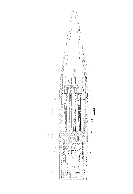
Fig. 1 is a longitudinal sectional view through the spin
stabilized projectile of this invention with the projectile
having a payload of subprojectiles;
Fig. 2 is a lateral cross section taken along line II-II
of Fig. 1; and
Fig. 3 is a dispersion diagram of a projectile in
accordance with Figs. 1 and 2.
In accordance with Fig. 1, a spin stabilized projectile
includes a projectile body 1, a ballistic cover or cone 2
attached to a front portion of projectile body 1 and an
ignitor or fuse 3 attached to the aft body or rear section of
projectile body 1, wherein fuse 3, in this example, takes the
form of a programmable delay time fuse 3. It is however quite
feasible to utilize a different fuse or igniter, for example
a distance fuse, whose firing or ignition is accomplished via
a transmission means. Projectile body 1 further includes a
functional or utility chamber 4 for a fixedly retained payload
5, an igniter chamber 6, located behind or aft of utility
chamber 4 and partially separated therefrom by a web 7, a
rotating band 8 and slots or grooves 9, for the attachment of
a non-illustrated but known cartridge case. A holding or
retaining screw 10 fixedly secures payload 5 in the axial
direction and also unites projectile body 1 and ballistic
cover or cone 2. Known delay time fuse 3, affixed in ignition
chamber 6, includes a fuse body 11, a data receiver spool 12,
an energy supply system 13, including a power generator for
example, an electronic delay ignition or time fuse module, an
igniter 15, a detonator 16 and a bursting charge 17.

2155 399
P13931.TR1
In accordance with this invention, the bursting charge 17 is
an explosive charge 17, wherein the explosive charge, in the
radial direction, is in tight contact with the igniter or
rather the delay time fuse 3 and/or with the projectile body
1 and, in the axial direction, is provided with a damping or
attenuating space 18 relative to web 7. If desired, explosive
charge 17 can be located directly in projectile body 1, in
which the ignition chain or circuit must be assured to the
igniter or the delay ignition fuse 3 or the detonator 16. The
damping space 18 can be in the form of an air gap between web
7 and explosive charge 17 in the manner illustrated in Fig. 1,
or, for example, while not illustrated, in the form of a
material, arranged between web 7 and explosive charge 17,
having damping properties for the detonation impulse wave.
In accordance with Figs. 1 and 2, in this exemplary
embodiment, payload 5 is comprised of a plurality of
cylindrical subprojectiles 20 of heavy metal, with the
subprojectiles forming coaxially arranged subprojectile
columns 21 in utility chamber 4. Eight superposed
subprojectiles 20 form one column 21 and nineteen such columns
21, as best seen in Fig. 2, are fixedly secured in the axial
direction in utility chamber 4 via holding screw 10.
Preferably, at the same time, the projectile body 1, in the
region of utility chamber 4, has the shape of a hollow
cylinder 22, with the hollow cylinder additionally having
recesses 23 in the axial direction. As shown in Fig. 2, in
cross section, six eccentric recesses 23, in the form of
sectors of circles, are utilized. By means of these recesses,
on one hand, subprojectiles 20 or rather subprojectile columns
21, are retained adjacently together and, in addition, are
secured against rotation via holding screw 10, as well as' on
the other hand, forming reference fracture locations 24, in

215S399
P13931.TR1
the axial direction, at the thinnest wall portions of
projectile body 1.
The mode of operation of the spin stabilized projectile is as
follows: Once igniter 16 is ignited, there occurs, via
detonator 16 and explosive charge 17, the expulsion of payload
5, i.e., subprojectiles 20. As a result of the arrangement of
explosive charge 17, the impulse waves of the detonation
function or operate immediately in the radial direction, in
terms of time, and operate in a delayed manner, in terms of
time, in the axial direction. As a result thereof, projectile
body 1 is ripped open laterally in the region of rotating band
8, and the utility chamber 4 is opened laterally, along
reference fracture locations 24 from a rear or aft portion of
the projectile body, for example much in the manner in which
a banana is peeled, and the side portions thereof, aided by
the centrifugal force are flung away. Limited via damping
space 18, payload 5 is only subjected to slight compression,
as a result of which the release of subprojectiles 20 is time
delayed and occurs substantially without interference. The
heavy metal subprojectiles of illustrated payload 5 then fly
singly, in a spin stabilized manner, toward the target in an
acute scattering angle.
Illustrated very well in Fig. 3 is the dispersion diagram of
such a projectile having 152 subprojectiles 20 and shows the
coaxial arrangement of the nineteen subprojectile columns 21,
each having eight subprojectiles 20 in utility chamber 4,
together with the substantially trouble free expulsion
thereof. For example, the bordered point or dot spiral 25
emanates from a subprojectile column 21 located at the largest
or greatest coaxial distance from the projectile axis and
point 26 emanates from a subprojectile 20 that abuts web 7.

21~399
P13931.TR1
As a payload S, other subprojectiles in other formations and
other arrangements can be utilized or be utilized for the
generation of false targets or rather for blinding or dazzling
of a flying target, or for CHAFF or FLARE payloads.

Dessin représentatif
Une figure unique qui représente un dessin illustrant l'invention.
États administratifs

2024-08-01 : Dans le cadre de la transition vers les Brevets de nouvelle génération (BNG), la base de données sur les brevets canadiens (BDBC) contient désormais un Historique d'événement plus détaillé, qui reproduit le Journal des événements de notre nouvelle solution interne.

Veuillez noter que les événements débutant par « Inactive : » se réfèrent à des événements qui ne sont plus utilisés dans notre nouvelle solution interne.

Pour une meilleure compréhension de l'état de la demande ou brevet qui figure sur cette page, la rubrique Mise en garde , et les descriptions de Brevet , Historique d'événement , Taxes périodiques et Historique des paiements devraient être consultées.

Historique d'événement

Description Date
Inactive : CIB de MCD 2006-03-11
Le délai pour l'annulation est expiré 2000-08-03
Lettre envoyée 1999-08-03
Accordé par délivrance 1999-06-01
Inactive : Page couverture publiée 1999-05-31
Inactive : Lettre officielle 1999-03-24
Inactive : Transferts multiples 1999-02-24
Inactive : Taxe finale reçue 1999-02-24
Préoctroi 1999-02-24
Un avis d'acceptation est envoyé 1998-09-04
Lettre envoyée 1998-09-04
Un avis d'acceptation est envoyé 1998-09-04
Inactive : Renseign. sur l'état - Complets dès date d'ent. journ. 1998-08-31
Inactive : Dem. traitée sur TS dès date d'ent. journal 1998-08-31
Inactive : Approuvée aux fins d'acceptation (AFA) 1998-07-13
Demande publiée (accessible au public) 1996-02-27
Exigences pour une requête d'examen - jugée conforme 1995-08-03
Toutes les exigences pour l'examen - jugée conforme 1995-08-03

Historique d'abandonnement

Il n'y a pas d'historique d'abandonnement

Taxes périodiques

Le dernier paiement a été reçu le 1998-07-30

Avis : Si le paiement en totalité n'a pas été reçu au plus tard à la date indiquée, une taxe supplémentaire peut être imposée, soit une des taxes suivantes :

  • taxe de rétablissement ;
  • taxe pour paiement en souffrance ; ou
  • taxe additionnelle pour le renversement d'une péremption réputée.

Les taxes sur les brevets sont ajustées au 1er janvier de chaque année. Les montants ci-dessus sont les montants actuels s'ils sont reçus au plus tard le 31 décembre de l'année en cours.
Veuillez vous référer à la page web des taxes sur les brevets de l'OPIC pour voir tous les montants actuels des taxes.

Historique des taxes

Type de taxes Anniversaire Échéance Date payée
TM (demande, 2e anniv.) - générale 02 1997-08-04 1997-07-22
TM (demande, 3e anniv.) - générale 03 1998-08-03 1998-07-30
Enregistrement d'un document 1999-02-24
Taxe finale - générale 1999-02-24
Titulaires au dossier

Les titulaires actuels et antérieures au dossier sont affichés en ordre alphabétique.

Titulaires actuels au dossier
OERLIKON CONTRAVES PYROTEC AG
Titulaires antérieures au dossier
PETER ETTMULLER
Les propriétaires antérieurs qui ne figurent pas dans la liste des « Propriétaires au dossier » apparaîtront dans d'autres documents au dossier.
Documents

Pour visionner les fichiers sélectionnés, entrer le code reCAPTCHA :


Pour visualiser une image, cliquer sur un lien dans la colonne description du document. Pour télécharger l'image (les images), cliquer l'une ou plusieurs cases à cocher dans la première colonne et ensuite cliquer sur le bouton "Télécharger sélection en format PDF (archive Zip)" ou le bouton "Télécharger sélection (en un fichier PDF fusionné)".

Liste des documents de brevet publiés et non publiés sur la BDBC .

Si vous avez des difficultés à accéder au contenu, veuillez communiquer avec le Centre de services à la clientèle au 1-866-997-1936, ou envoyer un courriel au Centre de service à la clientèle de l'OPIC.


Description du
Document 
Date
(aaaa-mm-jj) 
Nombre de pages   Taille de l'image (Ko) 
Revendications 1998-07-01 2 56
Abrégé 1996-02-28 1 16
Description 1996-02-26 5 192
Revendications 1996-02-26 2 55
Dessins 1996-02-26 1 32
Dessin représentatif 1999-05-24 1 13
Avis du commissaire - Demande jugée acceptable 1998-09-03 1 166
Avis concernant la taxe de maintien 1999-08-30 1 179
Correspondance 1999-02-23 1 47
Correspondance 1999-03-23 1 8
Demande de l'examinateur 1997-11-18 1 28
Correspondance de la poursuite 1998-04-23 2 45
Correspondance de la poursuite 1998-04-23 3 142
Courtoisie - Lettre du bureau 1999-03-23 1 13
Correspondance de la poursuite 1995-08-02 4 158