Sélection de la langue

Search

Sommaire du brevet 2155624 

Énoncé de désistement de responsabilité concernant l'information provenant de tiers

Une partie des informations de ce site Web a été fournie par des sources externes. Le gouvernement du Canada n'assume aucune responsabilité concernant la précision, l'actualité ou la fiabilité des informations fournies par les sources externes. Les utilisateurs qui désirent employer cette information devraient consulter directement la source des informations. Le contenu fourni par les sources externes n'est pas assujetti aux exigences sur les langues officielles, la protection des renseignements personnels et l'accessibilité.

Disponibilité de l'Abrégé et des Revendications

L'apparition de différences dans le texte et l'image des Revendications et de l'Abrégé dépend du moment auquel le document est publié. Les textes des Revendications et de l'Abrégé sont affichés :

  • lorsque la demande peut être examinée par le public;
  • lorsque le brevet est émis (délivrance).
(12) Demande de brevet: (11) CA 2155624
(54) Titre français: ROBINET DE VIDANGE
(54) Titre anglais: DRAIN VALVE
Statut: Réputée abandonnée et au-delà du délai pour le rétablissement - en attente de la réponse à l’avis de communication rejetée
Données bibliographiques
(51) Classification internationale des brevets (CIB):
  • F16L 55/07 (2006.01)
  • E03B 07/08 (2006.01)
  • F16K 51/00 (2006.01)
(72) Inventeurs :
  • PORFIDO, ERASMO (Suisse)
  • BAMBERGER, MICHAEL (Allemagne)
(73) Titulaires :
  • GEORG FISHER ROHRLEITUNGSSYSTEME AG
(71) Demandeurs :
  • GEORG FISHER ROHRLEITUNGSSYSTEME AG (Suisse)
(74) Agent: ROBIC AGENCE PI S.E.C./ROBIC IP AGENCY LP
(74) Co-agent:
(45) Délivré:
(22) Date de dépôt: 1995-08-08
(41) Mise à la disponibilité du public: 1996-02-12
Licence disponible: S.O.
Cédé au domaine public: S.O.
(25) Langue des documents déposés: Anglais

Traité de coopération en matière de brevets (PCT): Non

(30) Données de priorité de la demande:
Numéro de la demande Pays / territoire Date
P 44 28 453.5 (Allemagne) 1994-08-11

Abrégés

Abrégé anglais


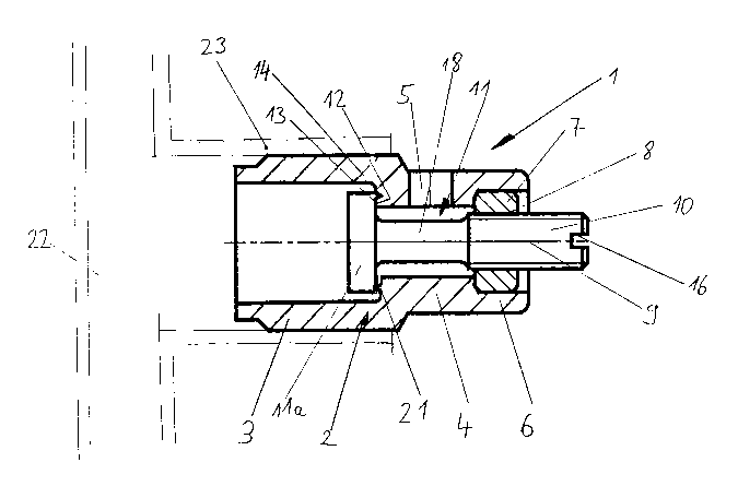
A drain valve (1) for emptying plastic lines,
particularly water lines, comprises a housing having different
hollow-cylindrical regions (3,4,6) and is composed of a
thermoplastic plastic. The housing is integrally or firmly
connectable to the line component part (22) at one end of the
drain valve. A threaded piece (7) is arranged at the housing
(2) at the other end of the drain valve (1), whereby the
thread (8) lies coaxially with the longitudinal axis (9) of
the drain valve. A spindle [or: stem] (11) having a piston-
like valve body (11a) is introduced in this thread (8). In
the closed position, the valve body (12) has its one piston
face (12) lying against the sealing face of the housing (13).

Revendications

Note : Les revendications sont présentées dans la langue officielle dans laquelle elles ont été soumises.


The embodiments of the invention in which an
exclusive property or privilege is claimed are defined as
follows:
1. Drain valve for emptying plastic lines,
especially water lines, composed of a housing connected to a
line component part and of a valve body arranged therein,
characterized in that the housing (4) of the drain valve (1)
is composed of plastic and is an integrated part of the line
component part (22) or can be connected thereto with material
lock.
2. Drain valve according to claim 1, characterized
in that the housing (2) of the drain valve (1) comprises a
connection piece (3) of plastic at one end for welding to the
line component part (22) and can be placed directly thereonto
or introduced directly thereinto.
3. Drain valve according to claim 2, characterized
in that the housing (2) of the drain valve (1) can be
connected to the line component part (22) by resistance
welding or by healing element welding.
4. Drain valve, particularly according to one of
the claim 1 to 3, comprising a housing and a valve stem guided
therein with the valve body that acts against a seal face at
the housing in the closed position, characterized in that the
valve body (lla) is fashioned piston-like and has its piston
face (12) facing toward the stem acting against the seal face
(13) of the housing (2).
5. Drain valve according to claim 4, characterized
in that the sealing piston face (12) of the valve body
comprises an annular projection (14), preferably having a
triangular cross-section, that is intended to abut against or
engage into the seal face (13) of the housing (2) in the

closed position.
6. Drain valve according to claim 4, characterized
in that the housing seal face (13) comprises an annular
projection, preferably having a triangular cross-section
against which the piston fade (12) of the valve body (11a) is
seated in the closed position.
7. Drain valve according to claim 4, characterized
in that, in the closed position, the piston face (12) of the
valve body (11a) can be tightly fitted/joined against a planar
seal face (13).
8. Drain valve according to one of the claims 1 to
7, characterized in that the valve body (11a) can be actuated
with a threaded arrangement (7,8,10).
9. Drain valve according to one of the claims 1 to
8, characterized in that the valve body (11a) is held in the
closed position by a compression spring (19).
10. Drain valve according to one of the claims 1
to 9, characterized in that the valve body (11a) closes in
flow direction of the valve.
11. Drain valve according to one of the claims 1
to 10, characterized in that the pressure of the medium (15)
against the sealing face (13) acts upon the valve body.
12. Drain valve according to one of the claims 1 to
11, characterized in that the housing (2) is manufactured of
a thermoplastic material.
13. Drain valve according to one of the claims 1
to 12, characterized in that the valve body and at least the
sealing face (13) of the housing (2) are of materials having

a different modulus of elasticity.
14. Drain valve according to one of the claims 1
to 13, characterized in that the valve body (11a) and the
housing (2) are of materials having the same modulus of
elasticity.

Description

Note : Les descriptions sont présentées dans la langue officielle dans laquelle elles ont été soumises.

2 ~ S ~ 6 2 '~
The invention is directed to a drain valve having
the features of the preamble of claims 1 and 4.
Drain valves of metal are known. These comprise a
connecting thread via which they are connectable to the line
component part of plastic. To that end, an insert of metal
must first be slipped onto a pipe connection part of the line
component part and must subsequently be firmly joined thereto,
for example with a clamped connection. The insert comprises
a connecting thread into which the valve is screwed. Seal
lo elements that, for example, are composed of rubber are
employed at the sealing locations. These seal elements have
a limited service life.
An object of the present invention is to create a
drain valve for lines, particularly water lines, of plastic
that requires fewer connection locations and, thus, requires
fewer seals and also comprises a long service life.
This object is achieved by the characterizing
features of claim 1. Further advantageous developments of the
invention are described in the claims that are dependent
20 thereon. What is thereby understood by line component part
is not only a part of the conduit itself but any component
part in such a line as well, for example a fitting [or:
accoutrement] such as a stop slide valve or the like.
The advantage of the invention is comprised therein
that the housing of the drain valve can be arranged directly
at the plastic line component part. It is placed thereonto
or thereinto and is subsequently welded thereto. A further
possibility is comprised therein that the housing of the drain
valve is integrated in the plastic line component part. All
30 embodiments lead thereto that the plurality of sealing
locations that could lead to loss of tightness are reduced [in
number]. Installation is simplified as a result of the low
number of mounting parts that are required in order to attach
the drain valve to the line component part of the plastic
line. When the housing is already integrated into the plastic
line component part, only the valve then still has to be built

2~62ll
n .
As a result of the structural fashioning of the seal
location between valve body and housing according to claim 4,
traditional seal elements, for example seal elements of
rubber, can be foregone. The embodiments of claims 10 and 11
especially contribute thereto.
The invention shall be set forth below with
reference to a number of exemplary embodiments shown in the
drawings. Shown in the drawing are:
10 FIG. 1 a longitudinal section through a drain valve;
FIG. 2 a longitudinal section through a modification of the
drain valve;
FIG. 3 a longitudinal section through a further modification
of the drain valve;
FIG. 4 a longitudinal section through a slide stop valve
having two drain valves.
Fig. 1 shows a drain valve 1 for draining water
conduits of a service water installation. The housing 2 of
the drain valve 1 is composed of a thermoplastic plastic. At
20 one end of the drain valve, the housing 2 is fashioned as a
welded hexagon nipple 3 via which the drain valve 1 is welded
to a line component part of aplastic conduit. The welded
hexagon nipple 3 is designed such at its outside diameter that
it can be placed into a connection piece 23 of the line
component part 22. The line component part 22 can be
fashioned, for example, as a machined part [or: preform], as
a shut-off device, as a distributor or as a conduit pipe.
The drain valve 1 has its welded hexagon nipple 3
joined to the line component part 22 by heated tool welding.
30 The welded hexagon nipple 3 or the connection piece 23 can be
equipped with an electrical winding (not shown) in order to
join the two parts be resistance welding. The drain valve 1
can also be fashioned such that it can be put in place not in
but at the connection piece 23 of the line component part 22.
A heated tool welding or resistance welding can thereby also
ensue.

21~S2~
A hollow-cylindrical section 4 whose inside diameter
is smaller than that of the welded hexagon nipple 3 adjoins
the welded hexagon nipple 3. The outside diameter can
likewise be smaller in this region. A drain opening 5 is
arranged approximately in the middle of the section 4. A pipe
connection (not shown) that indicates the mounting position
in downward direction can be arranged thereat. A threaded
piece 7 is firmly joined to the housing 2 at the inside in the
region 6 of the section 4, the inside thread 8 thereof lying
10 coaxially with the longitudinal axis 9 of the drain valve.
The threaded piece 7 is preferably composed of metal and can
be a commercially available nut. A valve stem 11, preferably
of metal, has its threaded part lo running in the thread 8
thereof. The stem 11 has a shank 18 at whose end the valve
body lla is arranged. The valve body lla is fashioned piston-
like and -- in closed position -- has its piston face 12
pointing toward the stem interacting [with] the sealing face
13 of the housing 2.
An annular projection 14 that comprises a triangular
20 cross-section is arranged close to the circumference at the
piston face 12 of the valve body lla. The water flow is
blocked when the projection 14 presses against the sealing
face 13 of the plastic housing 2 or, respectively, engages
thereinto. Another embodiment of the valve seal is shown in
the lower half of Fig. 1. An annular projection 21 that has
a triangular cross-section is arranged therein at the seal
face 13 of the housing. When the planar piston face 12
presses against the projection 21 -- which acts a line seal
--, the drain valve is closed. An additional seal element can
30 be dispensed with due to the geometrical shaping and the
pairing of materials. For example, the valve body lla can be
composed of a harder material than the seal face 13 of the
housing. A suitable pairing of materials, for example, is
metal for the valve body lla and plastic for the housing face
13.
The drain valve 1 is closed in the position shown

21~5~2l~
in Fig. 1. The spindle 11 can be brought into the open
position by turning the spindle 11 with the assistance of a
screwdriver that can be introduced into the slot 16 in the
threaded part 10. Instead of the slot 16, the spindle 11 can
also comprise some other head geometry in order to apply a
tool for actuating the spindle 11; for example, a square or
two parallel surfaces at the circumference can be provided for
an open-end wrench. There is also the possibility of
arranging a part, for example a level or a handwheel directly
lo on the spindle 11 in order to be able to actuate the spindle
without a tool. In the open position, the water flows past
the valve body lla, then into the inside bore of the middle
section 4 of the valve and then out through the discharge
aperture 5.
Fig. 2 shows a further modification of the drain
valve 1 having a different thread part. In this embodiment,
a threaded [or: tapped (dependent on inside or outside thread
--911)] sleeve that has a smaller outside diameter than the
threaded piece 7 is utilized instead of the threaded piece 7.
20 As a result thereof, this version can be more compactly
fashioned.
Fig. 3 shows a further modification of the drain
valve 1 having a compression spring arrangement. The valve
body lla and the piston shaft 18 are seated axially
displaceable in the housing 2 by a piston slide 20. A
compression spring 19 lies between piston shaft 18 and housing
3. The compression spring 19 is arranged such that it presses
the piston-like valve body lla against the sealing face at the
housing 13. In this embodiment, the piston face 12 lies
30 against the flat seal face of the housing 13. In addition to
the spring, the pressure of the agent lS promotes the tight
closure of the valve body lla against the seal face of the
housing 13. Pressing against the outer end of the piston
slide 20 suffices for emptying the water conduit. A tool is
not required for this purpose.
Fig. 4 shows another possible application of the

S 2 ~1
drain valve. The line component part 22 is part of a stop
slide valve, for example the inlet or outlet connection piece
thereof. The housing 2 of the drain valve 1 is integrated in
the housing 24 of the stop slide valve 22. The discharge
aperture 5 points in different directions depended on the
installed attitude of the stop slide valve. So that the water
flows off in the desired direction when the valve body lla is
opened, a ring 27 is pressed on over the discharge aperture
5 upon formation of an annular channel having a further
lo discharge aperture 26 which can be positioned independently
of the position of the discharge aperture 5. A handwheel 25
is arranged at the head of the spindle 11 for opening the
valve body lla. The further fashioning of the valve has
already been set forth above. Two drain valves 1 are arranged
lying opposite one another at the stop slide valve 22, so that
at least one drain valve can be actuated in every installed
attitude.

Dessin représentatif
Une figure unique qui représente un dessin illustrant l'invention.
États administratifs

2024-08-01 : Dans le cadre de la transition vers les Brevets de nouvelle génération (BNG), la base de données sur les brevets canadiens (BDBC) contient désormais un Historique d'événement plus détaillé, qui reproduit le Journal des événements de notre nouvelle solution interne.

Veuillez noter que les événements débutant par « Inactive : » se réfèrent à des événements qui ne sont plus utilisés dans notre nouvelle solution interne.

Pour une meilleure compréhension de l'état de la demande ou brevet qui figure sur cette page, la rubrique Mise en garde , et les descriptions de Brevet , Historique d'événement , Taxes périodiques et Historique des paiements devraient être consultées.

Historique d'événement

Description Date
Inactive : CIB de MCD 2006-03-11
Le délai pour l'annulation est expiré 1999-08-09
Demande non rétablie avant l'échéance 1999-08-09
Réputée abandonnée - omission de répondre à un avis sur les taxes pour le maintien en état 1998-08-10
Demande publiée (accessible au public) 1996-02-12

Historique d'abandonnement

Date d'abandonnement Raison Date de rétablissement
1998-08-10

Taxes périodiques

Le dernier paiement a été reçu le 1997-07-24

Avis : Si le paiement en totalité n'a pas été reçu au plus tard à la date indiquée, une taxe supplémentaire peut être imposée, soit une des taxes suivantes :

  • taxe de rétablissement ;
  • taxe pour paiement en souffrance ; ou
  • taxe additionnelle pour le renversement d'une péremption réputée.

Les taxes sur les brevets sont ajustées au 1er janvier de chaque année. Les montants ci-dessus sont les montants actuels s'ils sont reçus au plus tard le 31 décembre de l'année en cours.
Veuillez vous référer à la page web des taxes sur les brevets de l'OPIC pour voir tous les montants actuels des taxes.

Historique des taxes

Type de taxes Anniversaire Échéance Date payée
TM (demande, 2e anniv.) - générale 02 1997-08-08 1997-07-24
Titulaires au dossier

Les titulaires actuels et antérieures au dossier sont affichés en ordre alphabétique.

Titulaires actuels au dossier
GEORG FISHER ROHRLEITUNGSSYSTEME AG
Titulaires antérieures au dossier
ERASMO PORFIDO
MICHAEL BAMBERGER
Les propriétaires antérieurs qui ne figurent pas dans la liste des « Propriétaires au dossier » apparaîtront dans d'autres documents au dossier.
Documents

Pour visionner les fichiers sélectionnés, entrer le code reCAPTCHA :


Pour visualiser une image, cliquer sur un lien dans la colonne description du document. Pour télécharger l'image (les images), cliquer l'une ou plusieurs cases à cocher dans la première colonne et ensuite cliquer sur le bouton "Télécharger sélection en format PDF (archive Zip)" ou le bouton "Télécharger sélection (en un fichier PDF fusionné)".

Liste des documents de brevet publiés et non publiés sur la BDBC .

Si vous avez des difficultés à accéder au contenu, veuillez communiquer avec le Centre de services à la clientèle au 1-866-997-1936, ou envoyer un courriel au Centre de service à la clientèle de l'OPIC.


Description du
Document 
Date
(aaaa-mm-jj) 
Nombre de pages   Taille de l'image (Ko) 
Abrégé 1996-02-11 1 20
Description 1996-02-11 5 232
Revendications 1996-02-11 3 84
Dessins 1996-02-11 3 60
Dessin représentatif 1999-06-22 1 14
Courtoisie - Lettre d'abandon (taxe de maintien en état) 1998-09-07 1 189
Correspondance reliée au PCT 1995-11-09 1 28