Sélection de la langue

Search

Sommaire du brevet 2159855 

Énoncé de désistement de responsabilité concernant l'information provenant de tiers

Une partie des informations de ce site Web a été fournie par des sources externes. Le gouvernement du Canada n'assume aucune responsabilité concernant la précision, l'actualité ou la fiabilité des informations fournies par les sources externes. Les utilisateurs qui désirent employer cette information devraient consulter directement la source des informations. Le contenu fourni par les sources externes n'est pas assujetti aux exigences sur les langues officielles, la protection des renseignements personnels et l'accessibilité.

Disponibilité de l'Abrégé et des Revendications

L'apparition de différences dans le texte et l'image des Revendications et de l'Abrégé dépend du moment auquel le document est publié. Les textes des Revendications et de l'Abrégé sont affichés :

  • lorsque la demande peut être examinée par le public;
  • lorsque le brevet est émis (délivrance).
(12) Demande de brevet: (11) CA 2159855
(54) Titre français: SYSTEME D'ADAPTATION ELASTIQUE POUR DISPOSITIF MEDICAL
(54) Titre anglais: ELASTIC PLUG ASSEMBLY FOR MEDICAL DEVICE
Statut: Réputée abandonnée et au-delà du délai pour le rétablissement - en attente de la réponse à l’avis de communication rejetée
Données bibliographiques
(51) Classification internationale des brevets (CIB):
  • A61M 39/06 (2006.01)
(72) Inventeurs :
  • BRIMHALL, GREG L. (Etats-Unis d'Amérique)
(73) Titulaires :
  • BECTON, DICKINSON AND COMPANY
(71) Demandeurs :
  • BECTON, DICKINSON AND COMPANY (Etats-Unis d'Amérique)
(74) Agent: GOWLING WLG (CANADA) LLP
(74) Co-agent:
(45) Délivré:
(22) Date de dépôt: 1995-10-04
(41) Mise à la disponibilité du public: 1996-06-28
Requête d'examen: 1995-10-04
Licence disponible: S.O.
Cédé au domaine public: S.O.
(25) Langue des documents déposés: Anglais

Traité de coopération en matière de brevets (PCT): Non

(30) Données de priorité de la demande:
Numéro de la demande Pays / territoire Date
08/364,636 (Etats-Unis d'Amérique) 1994-12-27

Abrégés

Abrégé anglais


An elastic plug assembly is provided for selective penetration by a needle. The elastic
plug assembly comprises an elastic plug that is retained in a radially compressed state by a
rigid plug retainer. The combined elastic plug and rigid plug retainer may be secured in a
housing formed from an elastomeric material. The elastic plug may be penetrated by a needle.
Upon removal of the needle, the radially compressed elastic plug will be urged toward its
compressed condition with the space that had been occupied by the needle being completely
filled to effectively achieve the sealing function of the plug. Needles may repeatedly be
penetrated through the plug and removed as necessary, and the plug will efficiently return to its
substantially solid sealed state after each successive needle removal.

Revendications

Note : Les revendications sont présentées dans la langue officielle dans laquelle elles ont été soumises.


WHAT IS CLAIMED IS:
1. An elastic plug assembly for penetration by a needle comprising: a generally tubular
rigid plug retainer having opposed inner and outer surfaces, said inner surface defining a
selected cross-sectional dimension, a compressible elastic plug having an outer surface, which,
in an uncompressed condition of said plug, defines a cross-sectional dimension greater than
said internal cross-sectional dimension of said rigid plug retainer, said plug being compressed
and disposed in said rigid plug retainer with said outer surface of said plug being in abutting
face-to-face relationship with said inner surface of said rigid plug retainer.
2. The elastic plug assembly of Claim 1, further comprising a housing securely engaged
around said rigid plug retainer.
3. The elastic plug assembly of Claim 2, wherein portions of said housing engaging said
rigid plug retainer are formed from an elastic material for resiliently engaging said rigid plug
retainer.
4. The elastic plug assembly of Claim 3, wherein said housing is a Y-site connector
having first and second inlets and an outlet, said elastic plug retainer being securely engaged
in said first inlet of said Y-site fitting.
5. The elastic plug retainer of Claim 1, wherein said elastic plug is compressed to a
cross-sectional dimension equal to between 60%-85% of said cross-sectional dimension of said
plug in said unbiased condition.

6. The elastic plug assembly of Claim 5, wherein said elastic plug is compressed to a
cross-sectional dimension equal to approximately 70% of said cross-sectional dimension of
said plug in said unbiased condition.

Description

Note : Les descriptions sont présentées dans la langue officielle dans laquelle elles ont été soumises.

`-- 21598~
PATENT APPLICATION
P-251 3
s ELASTIC PLUG ASSEMBLY FOR MEDICAL DEVICE
BACKGROUND OF THE INVENTION
This invention relates to an elastic plug assembly for use on a medical device, such as a
catheter, that can be penetrated by a needle and that will reseal after removal of the needle.
0 This invention is particularly adapted for use on a catheter having a Y-site connector. Although
this invention will be discussed in connection with a catheter having a Y-site connector, it is to
be understood that this invention may be used in conjunction with any device which requires a
needle to pass through an elastic member that must reseal when the needle is removed.
Intravenous catheters may have Y-site connectors connected to their proximal end to
lS allow first and second flows of liquids into a patient. The first inlet of a Y-site connector may be
sealed with an elastic plug that can be penetrated by a needle to allow a healthcare worker to
inject liquid such as medication into the patient when needed. The second inlet to the Y-site
connector may be placed in communication with another liquid such as a standard saline
solution to provide a continual fiow of fluid to a patient. The needle passing through the elastic
20 plug in the first inlet is removed after the proper dosage of medication is provided to the patient.
If multiple doses of medication are required, the health care worker may subsequently cause a
needle to be penetrated through the elastic plug of the Y-site connector to continue the delivery
of medication.
Prior art plugs generally perform well. However, it has been found that the material of
25 these plugs may take a set to the needle, particularly if the needle remains in the plug for a
considerable period of time. Thus, when the needle is removed from the plug, a hole in the
plug remains where the needle had been. Subsequent needles penetrated through the plug

21~18~
are unlikely to enter the small hole left by the previous needle. Thus, the small hole will remain
in communication with ambient atmosphere and can cause leakage, evaporation or
contamination. Any contamination that may result typically will be caused by ambient
atmosphere communicating with either the liquid being administered or with bodily fluids.
5 However, a possibility may exist for bodily fluids escaping through the hole in the elastic plug to
contaminate people working in or near the patient to whom the Y-site connector is connected.
The potential for these problems becomes greater each time a needle is removed and
replaced, since the number of holes remaining in the elastic plug will increase. This problem is
encountered not only with Y-site connectors, but in other situations where elastic plugs are
0 periodically penetrated by needles.
SUMMARY OF THE INVENTION
It is therefore an object of this invention to provide an elastic plug assembly for a medical
device such as a catheter that can be penetrated by a needle and that will not leak after the
5 needle has been withdrawn
The elastic plug assembly of this invention includes an elastic plug that is held in
compression by a rigid plug retainer. The rigid plug retainer in turn may be held captive within
an elastic material that may function as the catheter hub. The elastic plug and the rigid plug
retainer both may be substantially cylindrical. The rigid plug retainer preferably defines a
20 cross-sectional dimension of between 60% and 85% of the non-compressed cross-sectional
dimension of the elastic plug. Thus, the elastic plug must be radially compressed by
approximately 15%40% for insertion into the rigid plug retainer.
The above and any other objects and advantages of the invention will be apparent upon
consideration of the drawings and the following detailed description.
2s

2159855
,
BRIEF DESCRIPTION OF THE DRAWINGS
The preferred embodiments are illustrated in the drawings in which like reference
numerals refer to like elements and in which:
FIG. 1 is an exploded perspective view of the elastic plug assembly of this invention in
s conjunction with a Y-site connector on an intravenous catheter;
FIG. 2 is an end elevational view of the elastic plug shown in FIG. 1,
FIG. 3 is an end elevational view of the rigid plug retainer shown in FIG. 1;
FIG. 4 is an end elevational view of the catheter hub shown in FIG. 1; and
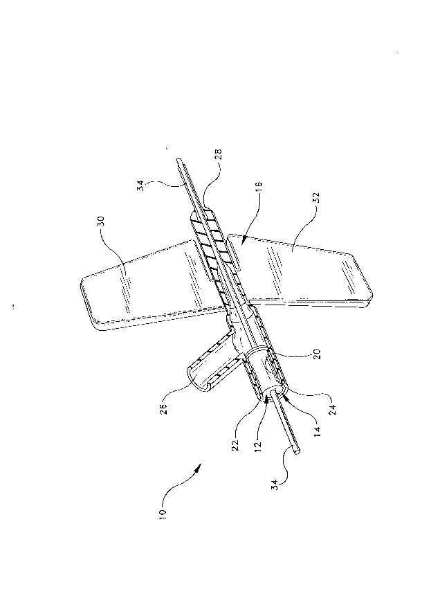
FIG. 5 is a perspective view, partly in section, of the elastic plug assembly of this
0 invention in conjunction with a Y-site connector on an intravenous catheter.
DETAILED DESCRIPTION OF THE PREFERRED EMBODIMENT
An elastic plug assembly in accordance with the subject invention is identified generally
by the numeral 10 in FIGS. 1 and 5. Elastic plug assembly 10 includes an elastic plug 12, a
1S rigid plug retainer 14 and a catheter hub 16.
With reference to FIGS. 1 and 2, plug 12 is formed from an elastomeric material to
define a solid cylinder with an outer cylindrical surface 18 defining a diameter "A".
Polyisoprene or latex could be used to form plug 12. Preferably, polyisoprene is used. Plug
retainer 14 is formed from a non-elastic rigid material and dehnes a tubular cylinder with an
inner cylindrical surface 20 and an opposed outer cylindrical surface 22. Polycarbonate, ABS
or stainless steel could be used to form plug retainer 14. Preferably, stainless steel is used.
Inner cylindrical surface 20 of plug retainer 14 has an inside diameter "B" selected such that
"B" approximately equals 60% to 85% of diameter "A." Outer cylindrical surface 22 of plug
retainer 14 defines an outside diameter "C".
2s Catheter hub 16 is formed from an elastomeric material such as polyurethane and
includes a hrst inlet 24, a second inlet 26 and an outlet 28 that extends to the catheter cannula.

21~9855
First inlet 24 and outlet 28 are substantially collinear with one another to facilitate passage of a
needle continuously through catheter hub 16, as shown in FIG. 5. Catheter hub 16 further
includes a pair of flexible planar wings 30 and 32 projecting outwardly from substantially
diametrically opposite sides of outlet 28. Wings 30 and 32 are flexible relative to outlet 28 and
s can be urged into substantially abutting face-to-face relationship with one another to facilitate
gripping and maneuvering of catheter hub 16 during insertion of the catheter into a patient.
Alternatively, wings 30 and 32 can be urged into a substantially coplanar orientation as shown
in FIGS.1 and 5 for taping catheter hub 16 in a fixed position on a patient. First inlet 24 of
fitting 16 defines an inside diameter "D" which is equal to or slightly less than outside diameter
o "C" of rigid plug retainer 14.
Plug assembly 10 is assembled into the condition shown in FIG. 5 by initially
compressing plug 12 radially approximately 15% to 40%, preferably 30%, so that the outside
diameter of plug 12 is reduced approximately to dimension "B". This compression of plug 12
may be simultaneous along the length thereof or may be gradual, beginning at one end and
5 continuing to the other. Plug 12, in its compressed condition, is then inserted into the central
aperture of plug retainer 14, such that inner circumferential surface 20 of plug retainer 14
securely engages outer circumferential surface 18 of plug 12 along at least a major portion of
the respective lengths. Thus, plug retainer 14 securely retains plug 12 in a state of radial
compression where plug 12 defines a diameter equal to approximately 70% of its initial non-
20 compressed diameter.
The subassembly of plug 12 and plug retainer 14 is then inserted into inlet 24 of catheter
hub 16. This insertion requires an outward stretching of the elastomeric material of iniet 24.
However, the elastomeric material of inlet 24 is resiliently urged toward an unbiased condition,
and hence securely grips the subassembly comprising plug 12 and plug retainer 14 in catheter
25 hub 16.

2i~985~ - -
Plug assembly 10 may be used in the conventional manner by inserting a needle 34approximately axially through plug 12 for communication with a patient. Needle 34 may be
removed when necessary and may be replaced with a new needle. Removal of needle 34 from
plug 12 permits the elastic material of plug 12 to return toward an unbiased condition in which
5 the cylindrical aperture that had been occupied by needle 34 is substantialiy filled. This sealing
of plug 12 after removal of needle 34 is positively assured by the radial compression of plug 12
achieved and maintained by plug retainer 14.
Thus, it is seen that needles may be passed through the compressed elastic plug in the
conventional manner, and may be removed and reinserted as necessary. The retention of the
o elastic plug in the compressed state by the rigid plug retainer ensures that the elastic material
of the plug will not take a permanent set to the needle, even when the needle has been in the
elastic plug for a considerable time. Thus, the radially compressed elastic material of the plug
will resiliently return toward a less compressed condition when the needle is removed to
completely fill the space that had been occupied by the needle. New needles may be
5 penetrated through the elastic plug and may be removed without adversely affecting the sealing
capabilities of the plug. Additionally, the radial compression of the elastic plug has no practical
effect on the ability of a health care worker to urge the needle through the plug.

Dessin représentatif
Une figure unique qui représente un dessin illustrant l'invention.
États administratifs

2024-08-01 : Dans le cadre de la transition vers les Brevets de nouvelle génération (BNG), la base de données sur les brevets canadiens (BDBC) contient désormais un Historique d'événement plus détaillé, qui reproduit le Journal des événements de notre nouvelle solution interne.

Veuillez noter que les événements débutant par « Inactive : » se réfèrent à des événements qui ne sont plus utilisés dans notre nouvelle solution interne.

Pour une meilleure compréhension de l'état de la demande ou brevet qui figure sur cette page, la rubrique Mise en garde , et les descriptions de Brevet , Historique d'événement , Taxes périodiques et Historique des paiements devraient être consultées.

Historique d'événement

Description Date
Demande non rétablie avant l'échéance 1999-10-26
Inactive : Morte - Aucune rép. dem. par.30(2) Règles 1999-10-26
Réputée abandonnée - omission de répondre à un avis sur les taxes pour le maintien en état 1999-10-04
Inactive : Renseign. sur l'état - Complets dès date d'ent. journ. 1998-12-30
Inactive : Abandon. - Aucune rép dem par.30(2) Règles 1998-10-26
Inactive : Dem. de l'examinateur par.30(2) Règles 1998-04-24
Demande publiée (accessible au public) 1996-06-28
Toutes les exigences pour l'examen - jugée conforme 1995-10-04
Exigences pour une requête d'examen - jugée conforme 1995-10-04

Historique d'abandonnement

Date d'abandonnement Raison Date de rétablissement
1999-10-04

Taxes périodiques

Le dernier paiement a été reçu le 1998-09-16

Avis : Si le paiement en totalité n'a pas été reçu au plus tard à la date indiquée, une taxe supplémentaire peut être imposée, soit une des taxes suivantes :

  • taxe de rétablissement ;
  • taxe pour paiement en souffrance ; ou
  • taxe additionnelle pour le renversement d'une péremption réputée.

Les taxes sur les brevets sont ajustées au 1er janvier de chaque année. Les montants ci-dessus sont les montants actuels s'ils sont reçus au plus tard le 31 décembre de l'année en cours.
Veuillez vous référer à la page web des taxes sur les brevets de l'OPIC pour voir tous les montants actuels des taxes.

Historique des taxes

Type de taxes Anniversaire Échéance Date payée
TM (demande, 2e anniv.) - générale 02 1997-10-06 1997-09-16
TM (demande, 3e anniv.) - générale 03 1998-10-05 1998-09-16
Titulaires au dossier

Les titulaires actuels et antérieures au dossier sont affichés en ordre alphabétique.

Titulaires actuels au dossier
BECTON, DICKINSON AND COMPANY
Titulaires antérieures au dossier
GREG L. BRIMHALL
Les propriétaires antérieurs qui ne figurent pas dans la liste des « Propriétaires au dossier » apparaîtront dans d'autres documents au dossier.
Documents

Pour visionner les fichiers sélectionnés, entrer le code reCAPTCHA :


Pour visualiser une image, cliquer sur un lien dans la colonne description du document. Pour télécharger l'image (les images), cliquer l'une ou plusieurs cases à cocher dans la première colonne et ensuite cliquer sur le bouton "Télécharger sélection en format PDF (archive Zip)" ou le bouton "Télécharger sélection (en un fichier PDF fusionné)".

Liste des documents de brevet publiés et non publiés sur la BDBC .

Si vous avez des difficultés à accéder au contenu, veuillez communiquer avec le Centre de services à la clientèle au 1-866-997-1936, ou envoyer un courriel au Centre de service à la clientèle de l'OPIC.


Description du
Document 
Date
(aaaa-mm-jj) 
Nombre de pages   Taille de l'image (Ko) 
Dessins 1996-06-27 3 49
Revendications 1996-06-27 2 41
Abrégé 1996-06-27 1 22
Description 1996-06-27 5 219
Dessin représentatif 1997-12-17 1 17
Rappel de taxe de maintien due 1997-06-03 1 109
Courtoisie - Lettre d'abandon (R30(2)) 1998-12-20 1 171
Courtoisie - Lettre d'abandon (taxe de maintien en état) 1999-10-31 1 184
Correspondance de la poursuite 1995-10-03 1 30
Demande de l'examinateur 1998-04-23 2 54