Note : Les descriptions sont présentées dans la langue officielle dans laquelle elles ont été soumises.
) 94/24394 216 ~ 12 6 PCT/US93/10141
DescriPtion
Door Assembly With Auqmented Counterbalancinq
Technical Field
This invention relates to non-vertically hinged doors and
associated counterbalancing mechanisms. More particularly, it
relates to counterbalancing mechanisms which substantially
exactly counterbalance the weight of the door at all angles
throughout its arc of motion.
10 Backqround Art
There are numerous applications in which a door is mounted
with a non-vertical hinge line and requires counterbalan~:ing. Such
applications include, among others, hatch covers for roof openings,
flush mounted sidewalk doors, and exterior basement entrance
1 5 doors.
Doors for use in these applications are often made of metal,
for strength and durability and, accordingly, can be quite heavy.
Counterbalancing allows the door to be opened and closed more
easily, and improves safety by reducing the tendency of the door
20 to close rapidly and with great force when released.
Typically, partial counterbalancing has been derived from
one or mofe torque rods, springs, gas cylinders or weights. Torque
rods have been particularly widely used because they provide a
counterbalancing torque as a result of the rotation of one end of
25 the rod relative to the other. Thus, the opposite ends of the torque
rod may be connected to the door and the door frame,
respectively, to provide a simple, but reliable, counterbalancing
mechanism. Through appropriate selection of the torque rod
diameter and length, a variety of doors of different weights and
30 sizes may be approximately counterbalanced with this direct
connection method.
Torque rods also have the advantage that their long, thin
shape can be positioned out of the way behind, or within the
thickness of the door frame, producing a door assembly that takes
35 the minimum space when held in inventory and is easy to transport
through the distribution chain. Moreover, torque rods are extremely
WO 94/24394 ?.,~ 60~ PCT/IJS93/10141
.,
-2-
rugged and reliable, an important consideration in doors which are
often used for exterior access or in exposed locations.
However, a torque rod counterbalancing design using the
simple direct connection between door and frame does not
5 perfect counterbalancing. This is because a torque rod provides a
counterbalancing torque which, in the usual operating range, is
linearly proportional to the amount of rotation or twist applied to it.
In contrast, a non-vertically hinged door requires a
counterbalancing torque which is non-linearly related to the
10 opening angle of the door. The weight of the door unsupported by
a non-vertical hinge line increases as a sinusoidal function of the
opening angle.
As a result, counterbalancing systems using torque rods
directly connected between the door and the frame only provide
15 exact counterbalancing for the door at two different opening
angles of the door. These angles may be found on a graph of
torque Imeasured at the hinge line) versus opening angle ~zero
degrees equals closed) where the line of torque rod generated
counterbalancing torque intersects the cosine curve of the torque
20 due to the unsupported weight of the door. For a horizontally
hinged door, the entire weight of the door is unsupported by the
hinge when the door is just being opened, and all the weight is
supported by the hinge as it reaches the fully open, ninety degree,
position.
While the specific two opening angles where the door is
exactly counterbalanced in a linear counterbalancing system are
under the designer's control, they have usually been selected to be
at approximately the fully open and fully closed positions. At the
fully open position no counterbalancing torque is required, and the
30 torque rod is not twisted. At the fully closed position, the torque rod
is adjusted to provide the exact counterbalance torque required for
the full weight of the door. Unfortunately, except at these two
angles, the door is insufficiently counterbalanced and may begin to
move if released.
In addressing this deficiency, subsequent designs for
counterbalancing systems have used a cam system with single or
multiple torque rods to nearly exactly counterbalance the door
~ 94/24394 21 6 01 2 ~ PCT/US93/10141
throughout its range of motion. In these designs, the torque rod is
not directiy connected between the door and the frame, but
instead acts through a cam which modifies the linear torque
produced by the torque rod to match the sinusoidal torque
5 needed to balance the weight of the door. Doors with
counterbalancing mechanisms of the cam-based type are seen in
United States Patent Nos. 4,873,791 and S, 136,811.
In such cam-based designs, the entire counterbalancing
force for the door is applied through the cam mechanism. The
10 present invention, however, uses a hybrid direct connection/cam
based design. A portion of the counterbalancing torque is
produced by one or more torque rods directly connected between
the door and the door frame, and the remainder of the
counterbalancing torque lthe "augmenting" torque), as needed to
15 provide nearly exact sinusoidal counterbalancing, is applied by one
or more additional torque rods through a cam system.
By applying the majority of the counterbalancing torque with
the directly connected torque rod, less force passes through the
cam system, which reduces friction and wear as compared to
20 earlier designs. Another advantage lies in the flexibility of the
choices available in a hybrid direct connection/cam based torque
rod design. Because torque rods are often available only in
standard diameters, it may be difficult to match the
counterbalance requirements of some doors. With the hybrid
25 design, differently sized torque rods may be combined to optimally
match the counterbalancing requirements of a wide variety of
doors.
Yet another advantage lies in the fact that the augmenting
torque rod counterbalancing system may be provided as a factory
30 installed option to a door also sold with only direct torque rod
counterbalancing, or it may be used as an add on field installed
accessory for an existing directly counterbalanced door.
Bearing in mind the above, it is therefore an object of the
- present invention to provide a new and improved
35 counterbalanced door and counterbalancing assembly in which
the counterbalancing is performed in part by a counterbalancing
mechanism producing linear counterbalancing and in part by an
WO 94/24394 PCT/US93/10141
6~ -4-
augmenting counterbalancing mechanism to counterbalance the
door throughout its arc of motion.
Disclosure of Invention
The invention comprises a counterbalancing assembly for
5 augmenting the counterbalancing of a partially counterbalanced
door and a complete door assembly incorporating the
counterbalancing assembly. The door assembly includes a frame,
a door hinged to the frame along a non-vertical hinge axis for
motion from an open position to a closed position and a first
10 counterbalancing means connected between the door and the
frame which produces a partial counterbalancing torque about
the hinge axis. The first counterbalancing means may comprise a
torque rod, or any other linear counterbalancing mechanism, and
may be connected directly between the frame and the door or
15 between the hinge leaves of the hinge mechanism upon which the
door is hinged.
The door assembly further includes an augmenting
counterbalancing system comprising a cam having a cam surface
and a second counterbalancing means which applies a force to
20 the cam surface to produce the augmenting counterbalancing
torque about the hinge axis of the door. The sum of the partial
counterbalancing from the first counterbalancing means and the
augmenting counterbalancing torque counterbalances the door
between the open and the closed positions.
In the preferred design, the first and second
counterbalancing means are torque rods which are twisted in
opposite directions as the door swings from the open to the closed
position. The second torque rod is mounted with a first end non-
rotatably connected to the frame and a second end rotatably
30 connected to the frame. A portion of the second torque rod is
bent outward from the axis of rotation of the second end and
contacts the cam surface at a point displaced from the axis of
rotation to provide the augmenting torque.
In the most highly preferred design, there are a total of four
35 torque rods in the counterbalancing assembly. The first
counterbalancing means includes first and third torque rods,
) 94124394 60126~ PCT/US93/10141
-5-
forming a pair, directly connected between the door and the
frame. The second counterbalancing means includes second and
fourth torque rods, forming a second pair, which act against first
and second cam surfaces to produce the augmenting torque.
The first and second cams are preferably integrally formed as
part of the door hinges. The hinges may be formed as gooseneck
hinges such that the hinge axis of the door is located beneath a
portion of the frame.
Brief Descri~tion of the Drawinqs
Fig. 1 is a perspective view of a horizontally hinged door and
frame assembly incorporating the counterbalancing mechanism of
the present invention.
Fig. 2 is a detail side elevational view, partly in section, of a
15 portion of the hinge mechanism and counterbalancing assembly
showing the door of Fig. 1 in the fully open position.
Figs. 3, 4 and 5 are side elevational views, partly in section,
co"es,~,onding to Fig. 2, but showing the door at different opening
angle positions as the door moves from the fully open position in Fig.
20 2 to the fully closed position of Fig. 5.
Fig. 6 is a detail side elevational view at an enlarged scale of
a gooseneck hinge leaf of the type seen in Figs. 1-5 with an integral
cam and cam surface.
Fig. 7 is a perspective view of first and third torque rods from
25 Fig. 1 which act directly between the door and frame to produce
partial counterbalancing of the door.
Fig. 8 is a perspective view of second and fourth torque rods
from Fig. 1 which act through the cam surfaces of two gooseneck
hinge as seen in Fig. 6 to produce the augmenting
30 counterbalancing of the door.
Modes for CarrYing Out the Invention
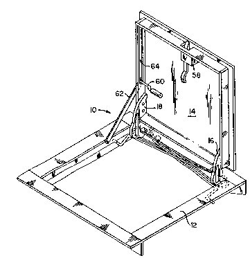
Figure 1 shows a perspective view of a door assembly
incorporating the augmented counterbalancing system of the
35 present invention. The door assembly 10 includes a frame 12 and a
door 14 hinged along a non-vertical hinge axis by gooseneck
WO 94/24394 ~ '' ` 6 PCT/US93/10141
hinges 16 and 18 shown at an enlarged scale in Fig. 6. Gooseneck
hinges 16 and 18 are fastened to the door 14 and rotate about
hinge pins 28, 30 extending through opening 20 in the hinge (see
Fig. 6) and into a corresponding opening in hinge mount 22.
In the preferred design the hinge pins 28, 30 are part of the
direct connection torque rods 24, 26 (seen in Fig. 7). They are
formed by the end of the torque rods 24, 26 which are reverse
curved to engage their corresponding hinge leaf with a direct
connection that also acts as a hinge pin. The door assembly
illustrated in Fig. 1 includes four (4) torque rods 24, 26, 32 and 34,
shown individually in Figs. 7 and 8. Torque rods 24 and 26 form a first
counterbalancing means which produces the linear
counterbalancing force through direct connection between the
door and frame. Torque rods 32 and 34 form a second
15 counterbalancing means which produce an augmenting
counterbalancing force by acting between the door and frame
through co"esponding cam surfaces on the gooseneck hinges.
The gooseneck hinge design of hinges 16 and 18 in Fig. 6
permit the hinge point to be located underneath the frame 12 and
20 still allow the door to reach the fully open position.
Referring to Fig. 7, torque rod 26 is a mirror image of torque
rod 24. Referring to Fig. 8, torque rod 32 is a mirror image of torque
rod 34. First torque rod 26 and second torque rod 32 act upon
gooseneck hinge 18 in the same way that their mirror images, third
25 torque rod 24 and fourth torque rod 34 act upon gooseneck hinge
16. As such, each hinge 16, 18 has fifty percent of the total
counterbalancing torque applied through it. Due to this symmetry,
and for the sake of clarity, in the cross sectional views of Figs. 2
through 5 the third and fourth torque rods 24, 34 have been
30 eliminated and only the first and second torque rods 26 and 32
have been shown.
Referring to Figs. 1, 2 and 7, the first torque rod 26 is
connected at its opposite ends between the door and the frame
by means of an upturned end 36 attached to the frame 12 and a
35 recurved end 30, 42 which engages hinge 18 on the door. The
uptumed end 36 is held in a holder 38, which is permanently
O 94124394 21601 PCT/US93/10141
fastened to the frame 12 and is retained therein by pin 40. The
recurved end includes a 180 bend from portion 42 to portion 30.
Portion 30, as previously described, passes through hole 20 in
hinge 18 and acts as a hinge pin along the hinge axis. Portion 42 is
5 engaged by recess 44 in hinge 18. In this way, the end 30, 42 is
non-rotatably connected to the door through hinge 18, and the
other end 36 is non rotatably connected to the frame.
This direct connection between the frame and the door
causes torque rod 26 to be twisted linearly as the door moves from
10 the fully open position of Fig. 2 ~torque rod 26 untwisted) to the fully
closed position of Fig. 5 (torque rod 26 twisted to its maximum
extent~. The length of torque rod 26 and its diameter are selected
such that the door is approximately fully counterbalanced when
the door reaches the fully closed position shown in Fig. S. Fifty
15 percent of the counterbalancing torque is, of course, provided by
torque rod 26 and fifty percent of the counterbalancing torque at
this position is provided by mirror image torque rod 24.
As described above, even in the absence of torque rods 32
and 34, the door will be nearly perfectly counterbalanced at the
20 fully open position shown in Fig. 2 and the fully closed position
shown in Fig. 5 by torque rods 24 and 26. Thus, at these two
positions, the torque rods 32 and 34 produce no augmenting
counterbalancing torque. However, at the intermediate positions
shown in Figs.3 and 4, the door is only partially counterbalanced by
25 torque rods 24 and 26 and torque rods 32 and 34 must produce an
augmenting torque that varies non-linearly with the opening angle
to produce the additional torque needed to produce near perfect
counterbalancing throughout the arc of motion of the door.
This augmenting torque is produced by modifying the force
30 from the torque rods 32 and 34 through cams on hinges 16, 18 to
produce the desired counterbalancing torque. Referring to Figs. 2
and 6, hinges 16, 18 include a cam portion 46 having a cam
surface 48.
Referring to Fig. 8, torque rod 32 includes a bent end 50
35 mounted in a holder 52 which, like holder 38, is permanently affixed
to the frame 12. The other end of torque rod 32 includes a double
bend from portion 54 to 56. Portion 54 contacts the cam surface 48
WO 94/24394 60~ PCT/US93/10141
-8-
on the hinge 18, and portion 56 is inserted into an opening in the
frame 12 to form a rotating connection relative to the frame 12. As
the door 14 moves from the open position in Fig. 2 to the closed
position in Fig. 5, the cam surface 48 presses down against portion
5 54 of torque rod 32 causing it to rotate about end 56. This rotation
defines a second axis of rotation through portion 56.
As indicated in Figs. 2-S, torque rod 32 rotates clockwise as
torque rod 26 rotates counter-clockwise. As the door closes, the
cam surface 48 rotates portion 54 around end 56 twisting the torque
10 rod 32. This twist generates an augmenting counterbalancing force
F1-F3 at each of the opening angles in Figs. 3-5 which is exerted in a
normal direction to the cam surface 48.
The counterbalancing force is directed by the shape of cam
surface 48 to act at a distance d from the first hinge axis. The
15 distance d is the perpendicular distance between the hinge axis of
the door and the line of force defined by the normal to the cam
surface at the point of contact 54 with the torque rod 32. This
relationship produces an augmenting counterbalancing torque
about the hinge axis which is the product of the augmenting
20 counterbalancing force times the distance d.
This product of force times distance varies exactly as required
to augment the partial counterbalancing torque produced by
torque rod 26. This may be more easily seen by reference to the
drawings and angles in Figs. 2 through 5. In the fully open position,
25 the door is balanced over the hinge axis and neither the first torque
rod 26 nor the second torque rod 32 is twisted. As the door 14
swings 90 to the closed position, torque rod 26 will also rotate 90
as indicated by the angle ~2. However, torque rod 32 rotates less
than 90 by virtue of the relationship with the cam. The maximum
30 angle of rotation of torque rod 32 is shown as H1 in Fig. 2.
At the first intermediate position shown in Fig. 3, torque rod 32
has begun to twist producing a small counterbalancing force F1
acting at a distance d1 from the first hinge axis. In Fig. 4, the door
has closed further causing an increase in the counterbalancing
35 force F2 acting at a new distance d2 to produce new
counterbalancing torque. In Fig. 5, the door has reached the fully
closed position and torque rod 32 has reached its maximum angle
94124394 1601,~? PCTIUS93/10141
of twist producing a maximum force F3. However, the shape of
cam surface 48 is such that F3 is aimed directly towards the hinge
axis of the door. Thus, the distance d3 is zero producing a net
augmenting counterbalancing force of zero at this angle.
In this way, the augmenting counterbalancing torque rod
produces a counterbalancing torque which is a minimum at the
fully opened position, reaches a maximum at an intermediate
position, and decreases to another minimum as the door reaches
the fully closed position. This is exactly the augmenting force
10 needed to fill in the missing counterbalancing torque from the
partial counterbalancing provided by torque rods 24 and 26.
The torque rod 32 may be allowed to directly contact the
cam surface 48 at point 54, however, the sliding friction and wear
can be reduced and door operation made quieter by snapping a
15 plastic sleeve 55 around the torque rod 32 at point 54.
Alternatively, a wheel may be mounted around the torque rod at
this point.
The door and frame of Fig. 1 also show a latch mechanism
58, a hold open arm 62 and a handle 60 which slides in a track 64.
20 Alternative designs for these elements would also be suitable and
will vary depending on the type of door and the desired locking
and closing mechanisms.
Thus, having described the invention, what is claimed is: