Note : Les descriptions sont présentées dans la langue officielle dans laquelle elles ont été soumises.
W094/2~267 216113 7 PCTMS94/04528
COMPOSITE ~LEMENT
Backqround of the Invention
The invention relates to elements formed of a
5 composition of glass fibers and reinforcing polymeric
resin.
It is well known to use compositions of glass
fibers for forming structural elements and, in
particular, non-load bearing structural elements, for
10 replacing heavier or more expensive materials. However,
in certain environments, e.g. within the passenger
compartments of modern aircraft, such composites are
often unable to meet strin~ent requirements of strength
and performance established for the safety of those
15 within that environment. These requirements may be
particularly strict where there is a perceived danger of
fire, as it is well-known that the performance of certain
polymeric-based materials may be unsatisfactory, or even
life-threatening, for reasons of heat release,
20 flammability, smoke release and/or toxic gas release, and
also for lack of strength, impact resistance and
compression resistance, making these materials unsuitable
for use in environments where they might otherwise
provide a substantial benefit.
SummarY of the Invention
According to the invention, a composite element
has a wall comprising glass fibers in web form with a
reinforcing polymeric binder, and a barrier film adapted
to render the wall impermeable to air, the composite
30 element in the presence of fire having levels of heat
release, flammability, smoke release and toxic gas
release below predetermined levels considered suitable
for use within the passenger compartment of a commercial
aircraft.
W094/25267 216 11~ 7 PCT~S94/04528
Preferred embodiments of the invention may include
one or more of the following additional features. The
barrier film comprises a metallic film, consisting, e.g.
essentially of aluminum, or a polymeric film, consisting,
5 e.g. essentially of nylon. The reinforcing polymeric
binder comprises chemical agents adapted to reduce the
rate of heat release, e.g. selected from the group
consisting of aluminum trihydrate and zinc borate. The
composite element has a peak heat release rate of less
10 than 50 kw/m2, and preferably less than 45 kw/m2, and a
two minute heat release of less than 50 kw-min/m2, and
preferably less than 45 kw-min/m2, when tested in
accordance with the requirements of FAR 25.853(a-1)
through Amendment 25-66 and FAR 121.312(a)(1) through
15 Amendment 121-198. Where a metallic barrier film is
employed, the composite element has a peak heat release
rate of less than 30 kw/m2 and a two minute heat release
of less than 30 kw-min/m2 when tested in accordance with
the requirements of FAR 25.853(a-1) through Amendment 25-
20 66 and FAR 121.312(a)(1) through Amendment 121-198. The
reinforcing polymeric binder comprises chemical agents
adapted to reduce levels of flammability, e.g. selected
from the group consisting of aluminum trihydrate and zinc
borate. The composite element has a burn length of less
25 than 3.0 i ncheC, and preferably less that 1.5 inches,
after 60 cecon~-C when tested in accordance with the
vertical flammability test specified in FAR 25.853(a) and
FAR 25.853(b). Preferably, the composite element of the
invention is further adapted to reduce the level of smoke
30 release, measured as specific optical density (D~) when
subjected to a four minute test, e.g., to 75 or less,
when tested is accordance with the requirements of FAR
25.853(a-1) through Amendment 25-66 and FAR 121.132
through Amendment 121-198.
W094/25267 216113 7 PCT~S94/04528
-- 3
Objectives of the invention include to provide a
composite element which, in the presence of fire, has
levels of heat release, flammability, smoke release and
toxic gas release below predetermined levels considered
5 suitable for use within the passenger compartment of a
commercial aircraft.
These and other features and advantages of the
invention will be apparent from the following description
of a presently preferred embodiment, and from the claims.
Brief Descri~tion of the Drawinq
Fig. 1 is a perspective view of an aircraft
passenger compartment equipped with structural, non-
weight bearing composite elements of the invention;
Fig. 2 is a somewhat diagrammatic exploded side
15 view of the lay-up of one embodiment of a composite
element of the invention;
Fig. 3 is a somewhat diagrammatic perspective view
of a continlls~s spiral tube forming operation for forming
a composite element of the invention in the form of a
20 duct;
Fig. 4 is a somewhat diagrammatic side view of the
emho~iment of a composite element of Fig. 2;
Fig. 5 is a somewhat diagrammatic side view of
another embodiment of a composite element of the
25 invention;
Fig. 6 is a somewhat diagrammatic side view of
still another embodiment of a composite element of the
invention; and
Fig. 7 is a somewhat diagrammatic side view of
30 still another embodiment of a composite element of the
invention.
DescriDtion of the Preferred Embodiment(s~
Referring to Fig. 1, the passenger compartment or
pressure shell 2 of a modern commercial jet aircraft 4 is
35 provided with improved structural, non-weight-bearing
W094125267 - 216113 7 PCT~S94/04528
composite elements of the invention, including, e.g.,
air-conditioning duct 6, ceiling panels 8 and wall panels
10 .
According to the invention, composite elements
5 suitable for use within the passenger compartment of a
commercial aircraft are formed, at least in part, of a
web of random or oriented non-woven or woven glass fibers
impregnated with a low heat release polymeric binder
cont~ining an unusually high percentage (by weight) of a
10 chemical flame retardant.
In the preferred embodiment, the polymeric binder
used in composite element is a commercially available
phenolic resin selected to have as low a heat release as
possible. The fire retardant agents that are combined
15 with the resin may comprise two or more componPnts that
act to reduce the heat release rate in a manner common to
the state-of-the-art. Examples of suitable fire
retardant agents and/or compositions include aluminum
trihydrate, zinc borate and similar chemicals.
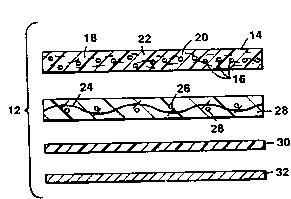
Referring to Fig. 2, the inventors have found that
in a composite element 12 of the invention, a non-woven
web 14 of fibrous material, e.g., filament glass fibers
16, provides a relatively high void volume, with a
substantially greater number of interstitial spaces or
2S voids 18 (as compared to woven fabrics) within which the
phenolic resin material 20 containing the chemical flame
retardant 22 may be retained. The comparatively high
resin content of the non-woven material imparts a
relatively greater stiffness, e.g. as compared to the
30 relatively lower stiffness of woven glass as a result of
its lesser ability to hold resin.
Still referring to Fig. 2, for improved strength,
this composite of the invention may include a layer of
woven cloth or coarsely woven, grid-like scrim 24, e.g.
35 also of fibrous material such as filament glass fibers
W094/25267 216113 7 PCT~S94/04528
-- 5
26, as an inert, strengthening element. The scrim 24 is
also im~ e~l.ated with phenolic resin 28.
The glass fibers carry the volume of polymeric
binder n~ceCcA~y to provide desired levels of stiffness,
- 5 strength and integrity in the composite element, while
the binder also contains a fire retardant to reduce the
heat release rate. The non-woven material has a high
void volume which provides sufficient space in the fiber
network for the polymeric binder and nPceFc~ry fire
10 retardants. The fibers in the non-woven sheet are not
interconnected, e.g. as in woven cloth, which permits the
fibers to move, e.g. with a mold, to conform to complex
mold features, including, e.g., double curved contours
and sharper radii, under pressure and/or heat during
15 molding operations.
A thin layer of polymeric film 30, e.g. a nylon
film 0.001 to 0.002 inch thick renders the composite wall
impermeable to flow of air (reduced air impermeability,
or complete impermeability to air, is desirable in
20 construction of ducts). The film is selected to bond to
the polymeric film upon application of heat and pressure
during the molding operation. The nylon film solvates
with the phenolic interface of the adjacent pre-preg
layer to form a chemical bond that im~Loves most
25 mech~nical properties, providing, e.g., improved flexing,
impact and shatter resistance, and hoop strength.
A layer of metallic film 32 can be included to
render the wall impermeable and to reflect heat, thus
lowering the heat release characteristics of the
30 composite element.
The composite element of the invention
demonstrates both a low level of flammability (burn
resistance) and a low heat release rate compatible with
its planned final application within the pressure shell
35 of a modern jet aircraft. In addition, the composite
W094/25267 PCT~S94/04528
2161137
-- 6
element demonstrates a low smoke release rate and a low
release of any toxic gases emitted by the combustion.
Methods for evaluation of composite elements, and the
performance of the composite element of the invention,
5 are described and quantified below.
Referring now to Fig. 3, according to one aspect
of the invention, an aircraft air-conditioning duct 6 of
the invention can be continuously formed in the manner of
a _piral tube, e.g. a multi-layer cardboard or paper
10 tube, using a tube forming machine 100 having a mandrel
102. The first layer 104 applied about the mandrel is a
thin polymeric, i.e. nylon, film, which in this
embodiment of an aircraft air-conditioning duct, also
provides air impermeability. A streng~hPning layer 106
15 of phenolic resin impregnated woven scrim is applied over
the nylon layer 104, and a non woven/phenolic resin "pre-
preg" layer 108 is applied over the scrim. The duct can
also be fabricated by winding, onto a mandrel, a strip
equal in width to the mandrel length. In this manner,
20 the composite is built up onto the mandrel by Cllcce-ccive
wraps (i.e., a "table wrap" method).
The layer of polymeric film may be disposed at
other positions within the composite element. However,
in formation of a duct by the mandrel process just
25 described, it is preferred to place the nylon film at a
position to form the interior wall of the duct. In this
position, the nylon film greatly aids in the release of
the completed cured duct from the tooling or mandrel upon
which it is formed. In the completed duct, it also
30 provides a smooth surface desirable for flow of air
within the duct. Also, where the composite element is a
relatively thin wall duct, the polymeric film serves to
lower the level of sound produced by flow of air within
the duct. The nylon film would limit absorption of water
35 into the duct wall.
W094/25267 216113 7 PCT~S94/04528
-- 7
Optionally, e.g. in instances where a very low
level of heat release is desired, a metallic, e.g.
- aluminum, film 110 is incorporated into the composite
element. In the case of a fire, the metallic film will
5 reflect a large segment of the exterior heat, and
incorporation of the metallic film into the composite
duct of the invention will further lower the heat release
rate, i.e. beyond the level obtained with the fire
retardants incorporated within the phenolic resin binder.
10 The metallic film may be employed to particular advantage
when incorporated at or near the outer surface of the
duct. If the polymeric film is used in conjunction with
the metallic film, it is preferably disposed at a side of
the metallic film opposite the side most likely to face a
15 source of heat or fire.
The composite element is treated by heat upon the
mandrel 102 to cause chemical bonding between the nylon
and phenolic resin, resulting in a duct 6 with very low
weight, but high heat resistance, elasticity and
20 resistance to impact. More importantly, performance of
the composite material of the duct in the presence of
fire more than exceeds the requirements for passenger
safety established by the F.A.A.
Working Exam~les
Composite elements of the invention are formed
with any of a number of combinations of materials using
glass fibers, in woven, non-woven or scrim form, and a
metallic film and/or a polymeric film.
The fiberglass woven cloth and fiberglass non-
30 woven mat are saturated with phenolic resin containing
appropriate amounts of suitable, state-of-the-art fire
retardant chemicals, e.g aluminum trihydrate, zinc borate
or the like. The finished, cured, resinated fiberglass
woven cloth composite element contains approximately 30
35 to 55% (by weight) phenolic resin. The f;ni~he~, cured,
W094l25267 216113 7 PCT~S94/04528
resinated fiberglass non-woven mat composite element
contains approximately 60 to 85% (by weight) phenolic
resin.
The following are typical material combinations
5 that might be employed in formation of a composite
element in the form of an air-conditioning duct of
aircraft.
ExamDle 1
Referring to Fig. 4, layer l (the outermost layer)
10 is a woven glass cloth 0.008 inch thick, 24x16 and 5.2
oz/yd2 (e.g., Style 1964 Woven glass tape, available from
Mutual Industries of Philadelphia, PA). Layer 2 is a
fiberglass non woven mat 1.4 oz/yd2 (e.g., Ultra-Mat No.
83095A, available from Elk Corporation of Ennis, TX).
15 Layer 3 is a metallic aluminum film 0.001 inch thick
(e.g., available from Reynolds Metal Co. of Richmond,
VA). Layer 4 is also a fiberglass non-woven mat 1.4
oz/yd2 (e.g., Ultra-Mat No. 83095A, Elk Co~oLation), and
layer 5 (the innermost layer) is also a woven glass cloth
20 0.008 inch thick, 24X16 and 5.2 oz/yd2 (e.g., Style 1964
Woven glass tape, Mutual Industries).
ExamDle 2
Referring to Fig. 5, layer 1 (the outermost layer)
is a woven glass cloth 0.008 inch thick, 24x16 and 5.2
25 oz/yd2 (e.g., Style 1964 Woven glass tape, Mutual
Industries). Layer 2 is a fiberglass non-woven mat 1.4
oz/yd2 (e.g., Ultra-Mat No. 83095A, Elk Corporation).
Layer 3 is a polymeric nylon film 0.001 inch thick (e.g.,
available from Richmond Aircraft Products of Norwalk,
30 CT). Layer 4 is also a fiberglass non-woven mat 1.4
oz/yd2 (e.g., Ultra-Mat No. 83095A, Elk Corporation), and
layer 5 (the innermost layer) is also a woven glass cloth
0.008 inch thick, 24x16 and 5.2 oz/yd2 (e.g., Style 1964
Woven glass tape, Mutual Industries).
35 ExamPle 3
W094l25267 21611~ 7 PCT~S94/04528
g
Referring to Fig. 6, layer 1 (the outermost layer)
is a woven glass cloth 0.008 inch thick, 24x16 and 5.2
oz/yd2 (e.g., Style 1964 Woven glass tape, Mutual
Industries). Layer 2 is a fiberglass non-woven mat 1.4
5 oz/yd2 (e.g., Ultra-Mat No. 83095A, Elk Corporation).
Layer 3 is also woven glass cloth 0.008 inch thick, 24x16
and 5.2 oz/yd2 (e.g., Style 1964 Woven glass tape, Mutual
Industries). Layer 4 (the innermost layer) is a
polymeric nylon film 0.001 inch thick (e.g., available
10 from Richmond Aircraft Products).
Exam~le 4
Referring to Fig. 7, layer 1 (the outermost layer)
is a fiberglass non-woven mat 1.4 oz/yd2 (e.g., Ultra-Mat
No. 83095A, Elk Corporation). Layer 2 is aluminum film
15 0.001 inch thick (e.g., available from Reynolds Metal
Co.). Layer 3 is also a fiberglass non-woven mat 1.4
oz/yd2 (e.g., Ultra-Mat No. 83095A), and layer 4 is also
a woven glass cloth 0.008 inch thick, 24x16 and 5.2
oz/yd2 (e.g., Style 1964 Woven glass tape, Mutual
20 Industries). Layer 5 (the innermost layer) is a
polymeric nylon film 0.001 inch thick (e.g., available
from Richmond Aircraft Products).
~ G
The composite elements formed according to the
25 examples were evaluated using the test methods described
for performance in the presence of fire. The composite
elements of the invention exhibited levels of heat
release, flammability, smoke release and toxic gas
release below predetermined levels considered suitable
30 for use within the passenger compartment of a commercial
aircraft.
In particular, composite elements of the invention
had a typical peak heat release rate of less than 50
kw/m2 (and typically less than 45 kw/m2) and a two minute
35 heat release of less than 50 kw-min/m2 (and typically
W094/25267 216113 7 PCT~S94/04528
-- 10 --
less than 45 kw-min/m2), when tested in accordance with
the requirements of FAR 25.853(a-1) through Amendment 25-
66 and FAR 121.312(a)(1) through Amendment 121-198.
Furthermore, those comrocite elements of the invention
5 including a metallic barrier film, when tested in the
same manner, exhibited a typical peak heat release rate
of less than about 30 kw/m2 and a two minute heat release
of less than about 30 kw-min/m2. By way of comparison,
the maximum peak heat release permitted by the FAA is 65
10 kw/m2 and the maximum two minute heat release permitted
by the FAA is 65 kw-min/m2.
Composite elements of the invention were also
tested ~for flammability, using the vertical flammability
tests specified in FAR 25.853(a) and FAR 25.853(b). The
15 composite elements of the invention had a burn length of
less than 1.0 inch after 60 seconds. Again, by way of
comparison, the maximum burn length permitted by the FAA
is 6.0 ~nchpc after 60 c~Con~c.
Composite elements of the invention were also
20 tested for the level of smoke release, measured as
specific optical density (D~), in accordance with the
requirements of FAR 25.853(a-1) through Amendment 25-66
and FAR 121.132 through Amendment 121-198. The composite
elements of the invention exhibited a typical (four
25 minute) specific optical density (4Dm) of 75 or less. In
contrast, the average maximum specific optical density
(4Dm) permitted by a major U.S. aircraft manufacturer is
150, while the FAA s~n~rd is 200.
In air permeability testing, a typical composite
30 element of the invention including a barrier layer of
polymeric film shows negligible air flow through the wall
at a pressure differential of 20 psi.
Composite elements of the invention also typically
exhibit tensile strength of at least 18,000 psi, and
35 burst strength of greater that 30 psi.
W094l25267 21611~ 7 PCT~S94/04528
-- 11 --
Composite elements in the form of lower weight
ducts (e.g. 1 oz/ft/in ID) also typically satisfy
- appropriate requirements for span load testing, compress-
to-break testing and impact testing.
Other emhoAiments are within the following claims.
For example, composite elements of the invention may be
employed in the form of other structural, non-weight
bearing elements of an aircraft passenger compartment,
e.g. wall and ceiling panels. In these and other
10 emhoAiments~ the order of the composite layers may be
varied as desired according to the desired application.
For example, in wall panels, where the non-woven layer is
to be the p~s-enger compartment side of the panel for
reasons of appearance, the metallic film may be applied
15 upon the nylon film, e.g. as the opposite surface layer,
in order to better retard penetration of heat into the
p~C enger compartment in the event of a fire.
Multiple layers of non-woven and/or woven pre-preg
material may be employed for adding bulk to the composite
20 element, and thus increasing wall thic~n~s and
stiffness, where such characteristics are desired.
Although the foregoing describes several
emhoAiments of a composite element of the invention, it
is understood that the invention may be practiced in
25 still other forms, including but not limited to with
greater or fewer layers, still within the scope of the
following claims.
What is claimed is: