Sélection de la langue

Search

Sommaire du brevet 2163055 

Énoncé de désistement de responsabilité concernant l'information provenant de tiers

Une partie des informations de ce site Web a été fournie par des sources externes. Le gouvernement du Canada n'assume aucune responsabilité concernant la précision, l'actualité ou la fiabilité des informations fournies par les sources externes. Les utilisateurs qui désirent employer cette information devraient consulter directement la source des informations. Le contenu fourni par les sources externes n'est pas assujetti aux exigences sur les langues officielles, la protection des renseignements personnels et l'accessibilité.

Disponibilité de l'Abrégé et des Revendications

L'apparition de différences dans le texte et l'image des Revendications et de l'Abrégé dépend du moment auquel le document est publié. Les textes des Revendications et de l'Abrégé sont affichés :

  • lorsque la demande peut être examinée par le public;
  • lorsque le brevet est émis (délivrance).
(12) Demande de brevet: (11) CA 2163055
(54) Titre français: CARTES PLIABLES DECOUPEES A LA FORME
(54) Titre anglais: FOLDABLE DIE CUT CARDS
Statut: Réputée abandonnée et au-delà du délai pour le rétablissement - en attente de la réponse à l’avis de communication rejetée
Données bibliographiques
(51) Classification internationale des brevets (CIB):
  • B42D 15/02 (2006.01)
  • B31F 01/00 (2006.01)
  • B42D 15/04 (2006.01)
(72) Inventeurs :
  • BRADLEY, STERLING E. LANI (Etats-Unis d'Amérique)
(73) Titulaires :
  • AMERICAN GREETINGS CORPORATION
(71) Demandeurs :
  • AMERICAN GREETINGS CORPORATION (Etats-Unis d'Amérique)
(74) Agent: NORTON ROSE FULBRIGHT CANADA LLP/S.E.N.C.R.L., S.R.L.
(74) Co-agent:
(45) Délivré:
(22) Date de dépôt: 1995-11-16
(41) Mise à la disponibilité du public: 1996-05-18
Requête d'examen: 2002-11-14
Licence disponible: S.O.
Cédé au domaine public: S.O.
(25) Langue des documents déposés: Anglais

Traité de coopération en matière de brevets (PCT): Non

(30) Données de priorité de la demande:
Numéro de la demande Pays / territoire Date
08/341,415 (Etats-Unis d'Amérique) 1994-11-17

Abrégés

Abrégé anglais


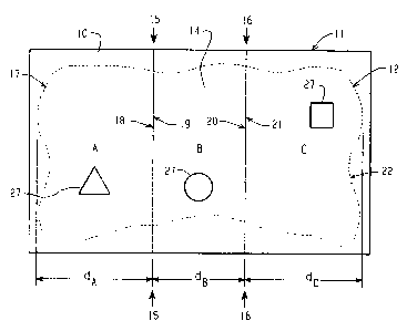
A foldable card and method of making has multiple panels connected by fold lines which
are placed laterally inward from free peripheral edges of end panels such that the card can be die
cut in a folded configuration around an entire periphery of the card without entirely eliminating
the fold lines. In a preferred method of making the cards, card stock is folded along the fold
lines prior to cutting. The fold lines of the card are spaced at intervals to define different widths
of adjoining panels so that when folded in a "Z" configuration a free peripheral edge of an end
panel overlaps or underlaps a fold line. There may be multiple fold line interconnected panels
between end panels. The fold lines may be oriented generally vertically or generally horizontally
relative to the face of the card. Abutting surfaces of two or more adjacent panels may be bonded
by adhesive at areas not coincident with adjoining fold lines in which case the fold lines between
such adhesively connected panels may be eliminated in the die cutting step. In an alternate
embodiment, a separate tipped-on panel is applied to a face of a folding panel of the card. The
peripheral edges of the tipped-on panel are die cut such that the fold lines are positioned laterally
inward from peripheral edges of the tipped-on panel so that the fold lines are not eliminated in
the cutting step.

Revendications

Note : Les revendications sont présentées dans la langue officielle dans laquelle elles ont été soumises.


The embodiments of the invention in which an exclusive
property or privilege is claimed are defined as follows:-
1. A foldable card cut from a single sheet of card stock, the card comprising multiple panels
joined along substantially parallel fold lines, a first panel having a free peripheral edge not joined
along a fold line, the card being foldable substantially flush against adjacent panels wherein the
free peripheral edge of the first panel extends laterally beyond a fold line joining second and third
panels.
2. The card of claim 1 wherein a fold line adjoining the first and second panels intersects
a peripheral edge of the third panel.
3. The card of claim 1 wherein one of the fold lines is of a length less than a length of a
peripheral edge of a panel joined to that fold line.
4. The card of claim 1 wherein a maximum width dimension of each of the panels is
substantially equal.
5. The card of claim 1 wherein the first panel is attached to the second panel at a surface
area of contact between the two panels not near a periphery of either panel and not coincident
with the fold line joining the two panels.
6. The card of claim 5 wherein a portion of the fold line connecting the first and second
panels is cut off.
7. The card of claim 5 wherein the first panel comprises a material different from a material
of the second panel.
8. The card of claim 1 further comprising more than three panels connected along fold lines.

9. The card of claim 1 wherein peripheral edges of the first, second and third panels not
joined along fold lines are substantially aligned when the card is completely folded.
10. The card of claim 1 wherein at least one of the panels has a peripheral edge configuration
different from a peripheral configuration of another panel of the card.
11. The card of claim 1 wherein one of the panels has a unique cut out portion.
12. The card of claim 1 further comprising a gap-jumping fold line which passes through a
cut-out portion of a peripheral region of a panel joined along the gap-jumping fold line.
13. A foldable card having multiple panels cut from a single sheet of card stock comprising
end panels and at least one intermediate panel joined along fold lines, the card being foldable
along the fold lines in a configuration wherein all of the panels are substantially flush against
adjacent panels and a free peripheral edge of an end panel extends laterally beyond a fold line.
14. A foldable greeting card having multiple panels connected at edges along fold lines
wherein a surface of a first panel is attached to a face of a second panel at an area not coincident
with a fold line, and wherein a fold line connecting edges of the second panel to a third panel
does not extend laterally beyond a free peripheral edge of the first panel not connected along a
fold line when the card is in a folded configuration.
15. The card of claim 14 wherein at least a portion of the first panel overlaps at least portions
of the fold line connecting the second and third panels.
16. The card of claim 14 wherein a free peripheral edge of the third panel extends at least
partially laterally beyond a fold line connecting the first and second panels when the card is in
a folded configuration.

17. The card of claim 14 wherein the first panel comprises a material different from the
second or third panel.
18. A method of making a foldable card having multiple panels including an end panel, and
foldable panels connected along fold lines, the method comprising the steps of:
folding a sheet of card stock material along fold lines into a configuration in which all of
the panels lie substantially flush,
cutting the card stock in the folded configuration along a line which at least partially
defines a periphery of the end panel, wherein the periphery of the end panel extends at least
partially beyond at least one of the fold lines.
19. The method of claim 18 further comprising the step of attaching an end panel to a
foldable panel at a surface area of contact not near a periphery of either panel and not coincident
with a fold line joining said foldable panel to an adjacent foldable panel.
20. The method of claim 18 further comprising the step of cutting at least one of the panels
prior to folding the card stock.
21. The method of claim 18 further comprising the step of embossing or debossing a portion
of the card stock prior to folding.
22. The method of claim 18 further comprising the step of applying a separate panel to one
of the end panels and cutting along a line which defines an entire periphery of the separate panel,
wherein the periphery of the separate panel extends at least partially laterally beyond one of the
fold lines.
23. The method of claim 18 wherein the step of cutting the outline of the card further
comprises cutting portions of the fold lines.

24. The method of claim 18 further comprising the step of attaching an end panel to an
adjacent intermediate panel at a contacting surface area of the two panels not near the periphery
of either panel and not coincident with the connecting fold line.
25. The method of claim 18 wherein the step of cutting along the line which defines the
periphery of the end panel cuts a portion of the fold line connecting the end panel and the
intermediate panel.
26. The method of claim 18 wherein the step of cutting the folded card stock is performed
simultaneously upon a plurality of folded sheets of card stock.
27. A foldable die-cut greeting card comprising multiple panels connected along fold lines,
and an end panel having one edge connected to an adjacent panel along a fold line and a free
peripheral edge not connected to an adjacent panel along a fold line, wherein a portion of a
periphery of said end panel is die-cut without eliminating entirely the fold line along which said
end panel is connected to an adjacent panel, and without eliminating entirely fold lines connecting
the adjacent multiple panels.
28. A foldable die-cut card comprising multiple panels connected at edges along fold lines to
adjacent panels, and an end panel having a width greater than a width of any of said multiple
panels, a surface of said end panel attached to a surface of one of said multiple panels, and
wherein said end panel is die cut about a periphery of said end panel, and wherein said fold lines
connecting edges of said multiple panels are not entirely eliminated from the card by said die-cut.
29. A method of making a foldable greeting card comprising the steps of folding a piece of
card stock along a fold line to form at least two panels joined along said fold line, attaching a
third panel to one of said two panels wherein said third panel is dimensioned to cover said fold
line, and cutting a peripheral edge of said third panel while in a folded configuration with the
other two panels without eliminating entirely the fold line.

Description

Note : Les descriptions sont présentées dans la langue officielle dans laquelle elles ont été soumises.


216305~
FOLDABLE DIE CUT CARDS
Field of the Invention
The present invention pertains in general to foldable greeting cards and, in particular, to
foldable greeting cards formed from a single sheet of card stock and having multiple panels, and
to cards having at least one panel which is structurally or materially different from other panels
of the card.
Bac~uund of the Invention
Foldable greeting cards having multiple panels connected by fold lines are desirable for
the large amount of graphic area provided and structural distinctiveness. Large scale
manufacture of such cards is difficult in processes in which the fold lines which connect the
panels are formed after the card is cut from card stock. Automated folding is difficult with cards
having non-linear peripheral edges to the panels. This is why folding cards are generally
rectangular and the fold lines extend the entire length of the panels.
To form multiple panel cards with panels having curved and/or intricately shapedperipheral edges, it is preferred to die cut around an entire periphery (360) of the front and back
panels of the card while the card is in a folded configuration. This, however, results in cutting
off the fold lines and thereby disconnecting the panels. U.S. Patent No. 4,558,980 discloses a
method of 360 die cutting a multi-panel card in a folded configuration wherein the fold lines
are cut off and the panels remain connected by adhesive applied proximate to common peripheral
~ges of adjoining panels at areas coincident with the fold lines.
It is also desirable to 360 die cut cards which have a uniquely finished or textured cover
panel which is adhesively attached or "tipped-on" to a folding panel of the card, whereby an
entire periphery of the front panel could be intricately shaped, along with the other panels of the

216~055
card. However, a similar problem arises in which the die cutting elimin:~tes the fold line which
connects the foldable panels, including the panel which supports the tipped-on panel. These
constraints of prior approaches to foldable multi-panel cards increase production costs and
thereby limit the number of card designs of this type available.
Brief Su~ of the Invention
The present invention provides a novel multi-panel card and method of making wherein
panels of the card are die cut about an entire periphery of the card without elimin:~ting fold lines
which connect the panels.
In accordance with one aspect of the invention, a multi-panel foldable card and method
of making includes end panels and at least one intermediate panel connected along generally
parallel fold lines spaced at intervals relative to free peripheral edges of the end panels to be
positioned laterally inward from the free peripheral edges when the card is in a fully folded
configuration so that the free peripheral edges of the end panels extend at least partially beyond
the fold lines, whereby the card in a fully folded configuration can be die cut about its periphery
without elimin~ting the fold lines along which the panels are connected.
In accordance with another aspect of the invention, a card and method of making includes
a tipped-on panel, separate from a foldable multi-panel portion of the card, adhesively attached
to an end panel of the multi-panel portion of the card, wherein the tipped-on panel is
dimen~ioned and adhesively attached relative to the multi-panel portion of the card such that an
entire periphery of the tipped-on panel can be die cut along with portions of the periphery of the
multi-panel portion when in a folded configuration without elimin~ting fold lines which connect
panels of the multi-panel portion of the card.
These and other aspects of the invention will be apparent upon reading and understanding
the following detailed description made with reference to the accompanying Figures wherein like
reference numerals refer to like elements.

21-6305~
_
Brief Description of the Figures
In the Figures:
3. 1 is a plan vlew of a slleet oP car~t stock havlng an outllnc o~' a card oP thc pre~ent
invention;
FIG. 2 is a perspective view of the sheet of FIG. 1 in a partially folded configuration;
FIG. 3 is a plan view of the sheet of FIG. 2 in a fully folded configuration;
FIG. 4 is a plan view of card stock in a folded configuration in an alternate embodiment
of the present invention;
FIG. 5 is a perspective view of a partially folded card of an alternate embodiment of the
present invention;
FIG. 6 is a perspective view of an alternate embodiment of the present invention in a
partially folded configuration, and
FIG. 7 is a perspective view of an alternate embodiment of the present invention in a
partially folded configuration.
Detailed Description of Plt;r~l~d Embo liml~ntc
FIG. 1 illustrates a sheet 10 of paper stock suitable for formation into a greeting card,
such as for example eighty pound paper, having generally straight boundary edges 11, and a
cutting outline 12 which defines peripheral edges of a multi-panel foldable card 14 to be cut from
sheet 10 in, for example, a die cutting operation. The outline 12 includes generally rectilinear
and parallel fold lines 15 and 16 which, along with peripheral cutting line 12, define in this
example three panels, A, B, and C. As will be apparent, other configurations of peripheral
cutting line 12 may be combined with two or more generally rectilinear parallel fold lines to
produce multi-panel foldable cards of differing configurations within the scope of the invention.
In a preferred method of making cards of the present invention, sheet 10 is folded along
fold lines 15 and 16 prior to cutting card 14 &om sheet 10 along peripheral cutting outline 12.
By tnis approach, sheet 10, having straight edges on all sides, is much more easily handled and
folded by high speed folding equipment than a pre-cut card having complex peripheral edges.
Furthermore, the 360 die cutting step of the method of the invention about an entire periphery
of the card in a folded state includes of at least portions of the fold lines. When manufactured

2163055
by this method, the finished cards are all pre-folded so that the end user is not required to crease
the card along one or more fold lines,
Once card 14 is cut from sheet 10, panel A becomes an end panel having a free peripheral
edge 17 which is not connected to a fold line, and an opposite lateral edge 18 connected at fold
line 15 to panel B. Panel B is an intermediate panel having lateral edges 19 and 20 connected
to fold lines 15 and 16 respectively. Panel C is an end panel having a lateral edge 21 connected
at fold line 16 to panel B and a free peripheral edge 22 not connected to a fold line.
A distance dA measured from, for example, free peripheral edge 17 to lateral edge 18 of
panel A perpendicular to fold line 15 represents a width of panel A. Similarly, a distance dB
measured perpendicularly between fold lines 15 and 16 r~resellts a width of panel B. And a
distance dc measured perpendicularly from fold line 16 to free peripheral edge 22 represents a
width of panel C. In this embodiment, by virtue of the relative lateral spacing of fold lines 15
and 16 and free peripheral edges 17 and 22, the width dB f panel B is less than the respective
widths dA and dc of end panels A and C. As a result of this difference in the widths of the
adjacent panels, when the card is folded in the manner shown in FIG. 2 (in a "Z" configuration),
free peripheral edge 17 of panel A overlaps or extends laterally beyond fold line 16 connecting
panels B and C, and free peripheral edge 22 of panel C extends laterally beyond and underlaps
fold line 15 when the card is in the fully folded configuration shown in FIG. 3. In other words,
when in the fully folded configuration, fold lines 15 and 16 lie laterally inward from free
peripheral edges 17 and 22. This "short-folding" of the card allows all panels of the card to be
peripherally die cut 360 at cutting outline 12 without entirely elimin~ting fold lines 15 and 16.
The placement of fold lines 15 and 16 laterally inward to the peripheral edges of the card allows
cutting outline 12 to be of any configuration which leaves a structurally sufficient amount of the
fold lines intact. Of course, the same folding and cutting may be applied to card or paper stock
which is "French folded" into a double thickness with a fold line across a top edge of the card.
FIG. 4 illustrates an example of another embodiment in which cutting outline 12 crosses
over and elimin~tes portions g of fold gapjumping fold lines 25 and 26 without detaching the
connected panels or compromising the structural integrity of the fold connection of the panels.
The exposure of free peripheral edge 22 of panel C adjacent fold line 15 allows the card to be
easily opened (unfolded) by grasping one or both free peripheral edges 17, 22.

2163055
, _
As shown in FIG. S, there may be multiple intermediate panels Bl,2,3.. cQ~ ecled by
multirl~ parallel fold lines f pocirinn~d to lie laterally inward from free penphe~al edge 17 and
extend laterally beyond frce p~ ,hel~l ed~e 22 when m a fully folded co~fiE~r~
FIG. 6 illustrates an alternate embodimen~ in which abutting surfa~es of panels A and B
are glued or othen~ise adhesively ~tt~ched, for P~ p'- along a glue line 23, at an area removed
from and not coincid~nt with fold line 15, thereby f~lrmin~ a cover having a thi~l~ness twice that
of panel C. This C~ .,( may be employed in the in~ ce where embossing or debossinE
is ~lrlJ...lcd upon, for ~Y~mpl~, panel A prior to cutting and folding. The adhesive ~t~chment
of panel B to the back of panel A covers the negative i~ ions of embossing/debossing in
panel A. Sheet 11 can be similarly die cut after folding and gluing of panel A to pa~el B.
e panels A and B are adhesively ~ d, fold line 15 may be CQmrl~tPly ~olimin~
wherein ~e edges of panels A and B ~ f ~' fold line 15 are cut flush w~th free p~iphPr.ql edge
22 of panel C. This method of mqnllfAr~ e eliminq~ the need to ~p~. ~rPly handle and position
panel A for adhesive ~tl Ak.... nt to panels B and C.
FIG. 7 ill4~ h ~ another P-,~hQ l;~ )t of the invention in whIch a s~p~r~te tip-on panel
T is adhesively ~ ^h~A to a front face of a panel D at an area not coi~cident with a fold line fT
conn~l lin~e panel D to other panels such as panel E. This card can also be die cut 360 when
fully folded such that t~he p~ ;rh~ 1 edge of the tip-on panel T is either coincid~-nt with peripheral
edges of the other panels or overlaps the ~ ;l.h. .~1 edges of the other panels. Consequently, tip-
on panel T ~ covers panel D and the panels A~t~ ~ thereto, and the fold line or lines
not ~ ted when panel T is die cut 360. In other words, the fold lines do not extend
laterally beyond ~e 1~ -- iphe~l edges of ti~on panel T. This fact enh~n~f s the frontal ~pp~-q~r~nce
of the card. As shown, a portion of a E~ -hF-~1 edge of ti~on panel T may cross over and
di~inqt~ a portion fTI of fold linc fT without c4l~yl4ll-;ci~ the support and hinge function of
the fold.
~ llltiple stacked cards of each of ~he emho~lim~ntc of the invention may be
simult~n~l~ly die cut in the folded configulation, ..helh~ or not one panel is glued to another.
Known card producli~--plU~xs and decorative trr~mt-ntc such as hot-sr~mrin~, die-cuttin~,
printing on both sides of the card stock, finishing, emhoccir~, silk screening, bronzing, etc., can
be readily inco,po-i-ted in the card pro~ n methsds of the present invention.

216305~
.~ ..
In a variation on one of the methods of the invention, pre-fold die cutting may be
performed upon sheet 11 to form, for example, individu~li7~d cut-out~ 25 in selgcted pE~ A a~
also shown in FIG. 1. By cutting such cut-outs prior to folding, the individualized cut-outs 25
can be made unique to selected panels. In another method of making of the invention, the multi-
panel card 14 may be cut out (along peripheral edge line 12) prior to formation of fold lines 15
and 16. This method may of course be applied to a stack of a plurality of card stock sheets 11
and allows the peripheral configurations of the panels to differ.
Thus a multiple panel foldable greeting card and method of making is disclosed in which
at least one of the panel-connecting fold lines is positioned laterally inward from a free peripheral
edge of the card when the card is in a folded configuration so that the card may be die cut 360
around the periphery of the card without cutting off the fold lines. Consequently, the fold lines
are concealed by the free peripheral edges of the end panels when the card is fully folded,
thereby improving the appeal~lce of the card.

Dessin représentatif
Une figure unique qui représente un dessin illustrant l'invention.
États administratifs

2024-08-01 : Dans le cadre de la transition vers les Brevets de nouvelle génération (BNG), la base de données sur les brevets canadiens (BDBC) contient désormais un Historique d'événement plus détaillé, qui reproduit le Journal des événements de notre nouvelle solution interne.

Veuillez noter que les événements débutant par « Inactive : » se réfèrent à des événements qui ne sont plus utilisés dans notre nouvelle solution interne.

Pour une meilleure compréhension de l'état de la demande ou brevet qui figure sur cette page, la rubrique Mise en garde , et les descriptions de Brevet , Historique d'événement , Taxes périodiques et Historique des paiements devraient être consultées.

Historique d'événement

Description Date
Demande non rétablie avant l'échéance 2006-11-16
Le délai pour l'annulation est expiré 2006-11-16
Inactive : CIB de MCD 2006-03-12
Réputée abandonnée - omission de répondre à un avis sur les taxes pour le maintien en état 2005-11-16
Inactive : Taxe finale reçue 2005-09-02
Préoctroi 2005-09-02
Un avis d'acceptation est envoyé 2005-06-30
Lettre envoyée 2005-06-30
Inactive : CIB attribuée 2005-06-17
Inactive : Approuvée aux fins d'acceptation (AFA) 2005-05-19
Modification reçue - modification volontaire 2003-02-10
Lettre envoyée 2002-12-20
Inactive : Renseign. sur l'état - Complets dès date d'ent. journ. 2002-12-20
Inactive : Dem. traitée sur TS dès date d'ent. journal 2002-12-20
Exigences pour une requête d'examen - jugée conforme 2002-11-14
Toutes les exigences pour l'examen - jugée conforme 2002-11-14
Demande publiée (accessible au public) 1996-05-18

Historique d'abandonnement

Date d'abandonnement Raison Date de rétablissement
2005-11-16

Taxes périodiques

Le dernier paiement a été reçu le 2004-11-03

Avis : Si le paiement en totalité n'a pas été reçu au plus tard à la date indiquée, une taxe supplémentaire peut être imposée, soit une des taxes suivantes :

  • taxe de rétablissement ;
  • taxe pour paiement en souffrance ; ou
  • taxe additionnelle pour le renversement d'une péremption réputée.

Les taxes sur les brevets sont ajustées au 1er janvier de chaque année. Les montants ci-dessus sont les montants actuels s'ils sont reçus au plus tard le 31 décembre de l'année en cours.
Veuillez vous référer à la page web des taxes sur les brevets de l'OPIC pour voir tous les montants actuels des taxes.

Historique des taxes

Type de taxes Anniversaire Échéance Date payée
TM (demande, 2e anniv.) - générale 02 1997-11-17 1997-11-10
TM (demande, 3e anniv.) - générale 03 1998-11-16 1998-11-16
TM (demande, 4e anniv.) - générale 04 1999-11-16 1999-11-16
TM (demande, 5e anniv.) - générale 05 2000-11-16 2000-10-23
TM (demande, 6e anniv.) - générale 06 2001-11-16 2001-11-16
TM (demande, 7e anniv.) - générale 07 2002-11-18 2002-10-30
Requête d'examen - générale 2002-11-14
TM (demande, 8e anniv.) - générale 08 2003-11-17 2003-11-04
TM (demande, 9e anniv.) - générale 09 2004-11-16 2004-11-03
Taxe finale - générale 2005-09-02
Titulaires au dossier

Les titulaires actuels et antérieures au dossier sont affichés en ordre alphabétique.

Titulaires actuels au dossier
AMERICAN GREETINGS CORPORATION
Titulaires antérieures au dossier
STERLING E. LANI BRADLEY
Les propriétaires antérieurs qui ne figurent pas dans la liste des « Propriétaires au dossier » apparaîtront dans d'autres documents au dossier.
Documents

Pour visionner les fichiers sélectionnés, entrer le code reCAPTCHA :


Pour visualiser une image, cliquer sur un lien dans la colonne description du document. Pour télécharger l'image (les images), cliquer l'une ou plusieurs cases à cocher dans la première colonne et ensuite cliquer sur le bouton "Télécharger sélection en format PDF (archive Zip)" ou le bouton "Télécharger sélection (en un fichier PDF fusionné)".

Liste des documents de brevet publiés et non publiés sur la BDBC .

Si vous avez des difficultés à accéder au contenu, veuillez communiquer avec le Centre de services à la clientèle au 1-866-997-1936, ou envoyer un courriel au Centre de service à la clientèle de l'OPIC.


Description du
Document 
Date
(aaaa-mm-jj) 
Nombre de pages   Taille de l'image (Ko) 
Dessin représentatif 1998-03-15 1 4
Dessins 1996-07-07 4 90
Revendications 2003-02-09 7 267
Description 1995-11-15 6 276
Abrégé 1995-11-15 1 31
Revendications 1995-11-15 4 151
Dessins 1995-11-15 4 53
Dessin représentatif 2005-05-18 1 10
Rappel de taxe de maintien due 1997-07-16 1 111
Rappel - requête d'examen 2002-07-16 1 127
Accusé de réception de la requête d'examen 2002-12-19 1 174
Avis du commissaire - Demande jugée acceptable 2005-06-29 1 160
Courtoisie - Lettre d'abandon (taxe de maintien en état) 2006-01-10 1 174
Correspondance 1996-07-07 5 111
Correspondance 2005-09-01 1 32