Note : Les descriptions sont présentées dans la langue officielle dans laquelle elles ont été soumises.
216S0~5
J- 962
CLOUD POINT AN~ POUR POINT ANALYZER
FIELD OF THE INVENTION
The present invention relates to determination of cloud and pour
point temperatures of a hydroc3.L~. More particularly, the present
invention relates to an apparatus and a method for automatically deter-
mining the cloud and pour polnt temperatures of a petroleum fraction
5 containing dissolved wax.
BACKGROUND OF THE IN~F~T~ON
Some petroleum fr~ctions p~rt~a~larly middle distillate petroleum
10 fuels and dark oils typ~c~lly containvar~ing quantities of dissolved wax.
Waxes are hydrocarbans of iligh rnole~lar weight which are solids at
about 70F or less suctl a5 p~rra~n~ microcrystalline. Wax has a
tendency to crystallize ~~ p~tfoleu~ fraction as the petroleum
fraction temperature decre~ses C~tallized wax causes the petroleum
15 fraction to cloud, become Visco~Js ~nd, as the temperature drops, to
solidify. A particular probl~n exists during the winter months when wax
crystallization caused by low oJt~oQ, temperatures can cause fuel lines,
filters and the like to clog In dlesel engines and furnaces which burn
petroleum fractions.
2 216~0~S
Pour point depressants such as kerosene and polymerized higher
esters of acrylic acid derivatives are well known in the art. When added
to a petroleum fraction, pour point depressants lower the cloud point and
the pour point temperature of the petroleum fraction. Kerosene is also
5 used as a diluent to lower the cloud point of petroleum fractions.
However, wax content within a petroleum fraction often varies with the
distillation conditions under which the fraction was produced and with the
source of crude oil from which the fraction was distilled. Thus, the
amount of pour point depressant needed to achieve a desired pour point
10 in a petroleum fraction will vary.
Standard tests have been developed by the American Society for
Testing and Materials (ASTM) to determine cloud and pour point tem-
peratures. The cloud point temperature test, ASTM D2300-91,
15 determines the temperature at which a cloud of wax crystals will form in a
volume of petroleum product. The pour point temperature test ASTM
D97-87 determines the lowest temperature at which a petroleum product
will flow. Both ASTM D2500-91 and D97-87 are manual tests which
require hands on manipulation of petroleum product samples to
20 determine cloud and pour point temperatures.
To account for weather extremes, it is generally desirable to utlllze
fuels (petroleum fractions) having pour points at least about 10-1 5F
below the anticipated operating temperature of a fuel. To depress the
25 cloud and pour point temperatures of fuels to a desired temperature it Is
common practice to remove a sample of fuel from a refinery production
stream, add a pour point depressant to the fuel sample, conduct ASTM's
D97-87 and D2500-91 to determine the pour point depressant's effect
on the sample and to repeat these steps until addition of pour point
3 216~045
depressant results in desired cloud and pour point temperatures in the
sample. A proportional amount of pour point depressant is then injected
into the process stream to lower the pour point of the fuel before it is
shipped for use. Since ASTM's D97-87 and D2500-91 are manual tests
5 this process is very time consuming.
Attempts have been made to eliminate the manual determination
of cloud and pour point temperatures. An apparatus utilizing a
microprocessor controlled photocell is available commercially from
10 Precision Scientific, Inc. of Chicago, Illinois, which determines the cloud
point temperature of a material. A separate apparatus utilizing air
pressure pulses to determine pour point temperature is also available
commercially from Precision Scientific, Inc. Alcor Engineering
manufactures a pour point tester utilizing a weighted ring which is visually
15 monitored for cessation of movement by the tester user to determine the
pour point temperature of a material. However, a single unitary
apparatus is not currently available to determine both cloud and pour
point temperatures of a material.
Therefore, a need exists for an apparatus and a method for using
the apparatus to automatically determining cloud and pour point tempera-
tures of petroleum fractions. A need also exists for an apparatus which
can be utilized on line with an automatic chemical feed system to depress
the cloud and pour point temperatures of petroleum fractions as they are
processed.
4 21650 15
It is an object of this invention to provide an apparatus and a
method of using the apparatus to automatically determine both cloud and
pour point temperatures of a petroleum fraction. It is also an object of
this invention to provide an apparatus which can be installed on-line with
5 a petroleum fraction production stream to automatically determine cloud
and pour point temperatures of a petroleum fraction taken from the
production stream. It is yet another object of this invention to provide an
apparatus and a method of using the apparatus to automatically depress
the cloud and pour point temperatures of a petroleum fraction to
10 temperatures less than or equal to predetermined temperatures.
SUMMARY OF THE INVENTION
To achieve the foregoing and other objects, and in accordance
15 with the present invention, as embodied and broadly described herein,
one characterization of the present invention comprises an apparatus for
automatic, determination of the cloud point temperature and the pour
point temperature of a petroleum fraction. The apparatus is comprised of
a receptacle having a chamber for holding a petroleum fraction sample; a
20 light emitting means attached to the receptacle and positioned to emit
light into the chamber; a light detecting means attached to the receptacle
and positioned to detect light emitted into the chamber by the light emit-
ting means; temperature measuring means attached to the receptacle for
measuring the temperature of the sample within the receptacle chamber;
25 heating means in thermal contact with the receptacle; cooling means in
thermal contact with the receptacle; motion producing means attached to
the receptacle; motion indicating means attached to said motion produc-
ing means; a motion detecting means positioned adjacent the motion
indicating means and a programmable logic controller in electrical com-
30 munication with the light detecting means, the temperature measuring
216 jO~5
means, the heating means, the cooling means, the motion producingmeans and the.motion detecting means. The programmable logic
controller controls heating, incremental cooling and testing of the
petroleum fraction sample to determine the cloud and pour point
5 temperatures of the petroleum fraction.
The method of the invention comprises incrementally cooling the
petroleum fraction sample and emitting light into the sample to determine
the cloud point temperature of the sample as indicated by light lost to
10 refraction due to wax crystallization. The pour point temperature of a
petroleum fraction sample is determined by incrementally cooling the
sample and using a movement indicator and motion detecting means to
detect that the sample has solidified.
15 BRIEF DESCRIPTION OF THE DRAWINGS
The accompanying drawings, which are incorporated in and form a
part of the specification, illustrate the embodiments of the present inven-
tion and, together with the description, serve to explain the principles of
20 the invention. Inthedrawings:
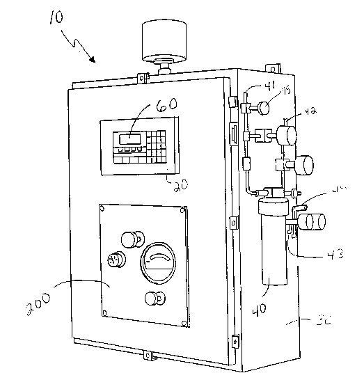
Figure 1 is a perspective view depicting the cloud point tempera-
ture and pour point temperature analyzer apparatus of the present in-
vention;
Figure 2 is a sectional view depicting the receptacle of the present
invention;
21650~
Figure 3 is a partially cut-away sectional view depicting the motion
indicating means;
Figure 4 is a partially cut-away sectional view depicting the motion
5 indicating means;
Figure 5 is a cross-sectional view taken along lines 5-5 of Figure 2;
Figure 6 is a cross-sectional view taken along lines 6~ of Figure 2;
Figure 7 is a cross-sectional view taken along lines 7-7 of Figure 2;
and
Figure 8 is a cross-sectlonal vlew taken along lines 8-8 of Figure 2
DETAILED DESCRIPTION OF THE PREFERRED EMBODIMENTS
An automatic cloud po~t t~rature and pour point temperature
analyzer apparatus is shown g~ner~lly as 10 in Figure 1.
The apparatus is c~npr~s~d d ~ receptacle 11, a light emitting
means 12, a light detect;n~ m~ns ~3 tennperature measuring means 14.
heating means 15, a mot;on po~g moans 17, a motion indicating
means 18, a motion detecting m~n~ 19 as shown in Figure 2, cooling
25 means 16 shown in Figw~s ~ d ~ ~nd a programmable logic controller
20 shown in Figure 1.
7 21~50~
Receptacle 11 is constructed of thermally conductive material such
as aluminum, stainless steel, ceramic or the like, having a sample inlet
port 21, a gas purge port 22 and a sample outlet port 23 as shown in
Figure 2.
Light emitting means 12 is preferably an optical fiber light source
which emits light into chamber 24 of receptacle 11. Light detecting
means 13 detects light within chamber 24 which is emitted from light
emitting means 12 and which is transmitted through a petroleum fraction
10 sample 100. Both light emitting means 12 and light detecting means 13
are electrically connected to programmable logic controller 20 which
controls when emitting means 12 emits light and electronically records
and stores the amount of light detected by detecting means 13. Light
emitting and detecting means of this type are available commercially from
15 Omron of Schaumburg, Illinois. Programmable logic controllers of this
type are available from Texas Instruments/Siemans of Johnson City,
Tennessee.
Temperature measuring means 14 are preferably a plurality of
20 dual thermocouples as are well known in the art shown in Figures 2, 7
and 8, which measure the temperature of sample 100. Temperature
measuring means 14 are electronically connected to programmable loglc
controller 20 which electronically records and stores the temperature of a
sample 100.
2l6sn~s
Heating means 15 are preferably a plurality of heating rods, having
a ceramic core wrapped by a heating wire as are well known in the art,
positioned as shown in Figures 2 and 8. Cooling means 16 are
preferably a plurality of liquid cooled, solid state cold plates attached to
5 the sides of receptacle 13 as shown in Figures 7 and 8. The cold plates
are generally comprised of a front plate 70 in thermal contact with
receptacle 11, a thermoelectric module layer 71 and a liquid cooled back
plate 72. Cold plates of this type are available commercially from
Thermoelectric Cooling American Corp., Chicago, Illinois. Both heating
10 means 15 and cooling means 16 are electrically connected to
programmable logic controller 20 which controls actuation of the heating
and cooling means.
Motion producing means 17 is preferably an air actuated cylinder
15 having a body 50 and a piston 51, such as available from Bimba Manu-
facturing of Monee, Illinois. Shaft 52 has a head portion 53, a mid-portion
54 and an attachment portion 55 attached to piston 51 as shown in
Figure 2. Motion producing means 17 is attachable to a pressurized air
source (not shown) which actuates piston 51. Programmable Logic
20 Controller 20 actuates the pressurized air source and thus controls
actuation of motion producing means 17.
Motion indicator means is a means which indicates when a sample
of fuel has solidified by ceasing motion. Motion indicator means 18 is
25 preferably comprised of a top member 27, slideably attached to shaft 52
at orifice 31, and attached to a plurality of legs 28 which attach top
member 27 to bottom member 29. Bottom member 29 is preferably a flat
ring as shown in Figures 6.
21~50~
Motion detecting means 19 is preferably a proximity sensor as is
well known in the art which is electronically connected to programmable
logic controller 20 which records and stores whether or not top member
27 of motion indicator means 18 is in proximity to motion detecting means
5 19.
Receptacle 11 is enclosed by a housing 30 as shown in Figure 1.
Housing 30 provides a convenient cabinet for storage, and protection
from the environment for the apparatus components. As shown in Figure
1, housing 30 includes an enclosure protection system 200 which
reduces the hazardous area rating within the enclosure to a non-
hazardous rating by maintaining positive air pressure within housing 30
to prevent intrusion of explosive vapor into housing 30. Enclosure
protection systems are available commercially from Bebco Industries of
15 Texas City, Texas. Hydroscopic dryer 40 is attached to housing 30 and
is in fluid communication with a petroleum fraction source (not shown) at
inlet 41 and in fluid communication with receptacle 11 at sample inlet
duct 43 and sample outlet duct 44. Hydroscopic dryer 40 is preferably a
dryer which utilizes a salt such as sodium chloride or potassium chloride
20 to remove trace water from the fuel sample prior to sample cloud and
pour point determination. Sampie outlet duct 44 is also in fluid
communication with the petroleum fraction source (not shown). The
petroleum fraction source is preferably a petroleum fraction processing
stream.
Apparatus 10 determines cloud point temperature by incrementally
cooling a petroleum fraction sample and using light refraction to indicate
crystal formation. Pour point temperature is determined by incrementally
lowering a samples temperature until a motion indicator becomes frozen
30 within the solidified sample. To utilize apparatus 11 a petroleum fraction
~16~0 1~
sample 100 is removed from a source such as a petroleum fraction
processing stream and is injected into inlet 41. Fuel sample 100 is
passed through hydroscopic dryer 40 to remove any trace water from the
sample which may interfere with cloud point or pour point temperature
determination and is injected into receptacle 11 via duct 43 shown in
Figure 1 which is connected to inlet 21 shown in Figure 2. Sufficient
sample 100 is added to chamber 24 of receptacle 11 to submerge bottom
member 29 of indicating means 18 as shown in Figure 2. The cloud and
pour point temperatures of sample 100 are determined by:
a) heating sample 100 to at least 11 5F by energizing heating
means 15;
b) emitting iight into chamber 24 and into sample 100 by
energizing light emitting means 12;
c) detecting the light transmitted from emitter 12 through sam-
ple 100 by light detecting means 13;
d) cooling sample 100 by deenergizing heating means 15 and
activating cooling means 16;
e) emitting light into sample 100 by energizing light emitting
means 12;
f) detecting the light transmitted from emitter 12 through sam-
ple 100 by light emitting means 13;
g) comparing the amount of light detected in step f) to the
amount of light detected in step c) to determine the percent amount
of light lost to refraction by wax crystal formation using the equation:
216504~
Lc Lf
x 100 = LL
Lc
where: Lc is the amount of light detected in step c,
Lf is the amount of light detected in step f, and
LL is the percent amount of light lost to refraction;
h) repeating steps d) - g) until LL is about 2% or greater;0
i) when LL is about 2% or greater, recording the cloud point
temperature of sample 100;
j) cooling sample 100 of step i) by at least 5F;
k) moving motion indlcatln~ means 18 by actuating motion
producing means 17;
I) detecting the "lo~Qn~d motion indicating means 18 by
motion detecting means 19
m) repeating steps j) l~ until no movement of motion indicating
means 18 is detected ~ n-a an ~ecting means 19;
n) recording the po~ pci;~ t~.. ~rature of sample 100 of step m)
12 21650~S
Steps a) - i) are performed by programmable logic controller 20 to
automatically determine the cloud point of sample 100 by determining the
temperature at which enough wax crystals have formed in sample 100 to
cause refraction of at least about 2% of the light emitted into sample 100
5 by light emitting means 12. Light refraction of 2% generally indicates
enough wax crystal formation to be seen by the naked eye therefore
indicating cloud point temperature. Programmable logic controller can be
adjusted to record a cloud point temperature at varied amounts of light
lost to refraction depending on the user's needs.
Steps j) - n) are performed by programmable logic controller 20 to
automatically determine the pour point of sample 100. At temperatures
above the pour point of sample 100, in step k), actuation of motion
producing means 17 causes shaft 26 to move from the configuration
shown in Figure 2 in which top member 27 rests on shoulder 30 of shaft
52 and in which top member 27 is in proximity of motion detecting means
19, to the configuration shown in Figure 3 in which top member 27 rests
on shoulder 30 of shaft 52 and in which top member 27 is not in proximlty
of motion detecting means 19. In step 1), when motion detecting means
20 19 detects that top member 27 is no longer in proximity, programmable
logic controller 20 repeats steps j) - I). When repeated cooling lowers the
temperature of sample 100 to the point where wax crystal formation has
solidified sample 100, and after motion producing means 17 moves piston
26 and shaft 52, the solidified sample 100 freezes bottom member 29 in
25 place. Top member 27 is then prevented from movement by legs 28
which are attached to bottom member 29. Top member 27 slides along
shaft 52 in orifice 31 of member 27 and remains in proximity of motion
13 . 21650 15
sensor 19. This configuration is shown in Figure 4. When programmable
logic controller 20 recognizes that piston 26 has been moved and that top
member 27 is still in proximity to motion sensing means 19 the program-
mable logic controller records that the pour point temperature of the
5 sample has been reached.
The recorded cloud and pour point temperatures are displayed on
display panel 60 shown in Figure 1 which is electrically connected to
programmable logic controller 20. Thus, controller 20 automatically
10 heats, incrementally cools and tests sample 100 to determine the cloud
point temperature and pour point temperature of sample 100.
ASTM D97-87 requires that the pour point temperature be checked
at 5F intervals. If the frequency is increased, it is possible to obtain a
15 falsely lower pour point temperature due to disturbance of the wax crystal
structure caused by movement of the motion indicator within sample 100.
Solidified sample 100 is removed from chamber 24 by:
o) ceasing cooling with cooling means 16 and energizing
heating means 15 until sample 100 is pourable, and
p) injecting pressurized gas into chamber 24 through gas
purge port 22 and adding fresh fuel into chamber 24 by inlet 21.
Steps o) and p) melt and force sample 100 out outlet 23 and out of
duct 44 thereby purging the tested sample.
Duct 44 is in fluid communication with the fuel source, thus
sample 100 is returned to its source.
14 ~ 21650'~5
If the recorded cloud and pour point temperatures are not low
enough for the desired utility of the hydrocarbon, a known amount of
cloud and/or pour point depressant can be added to the petroleum
fraction source, a fresh sample of depressed petroleum fraction is input
5 into chamber 24 and steps a) - i) are repeated to determine a new cloud
point for the depressed sample. Steps a) - i) are repeated until enough
cloud point depressant has been added to the petroleum fraction to
achieve a desired cloud point temperature. Similarly, a pour point
depressant can be added to the petroleum fraction source, a fresh
10 sample of depressed petroleum fraction is added to chamber 24 and
steps j) - p) are repeated to determine a new pour point for the depressed
sample. Steps j) - p) are repeated until enough pour point depressant
has been added to the petroleum fraction to achieve a desired pour point
temperature. Controller 20 is preferably utilized with an automatic
15 chemical feed system such as PaceSetter(~ (U.S. Patent No. 4,897,797)
available commercially from Betz Laboratories, Inc. to automatically add
the pour point depressant into the petroleum fraction source.
21650~
As an alternative to automatically adding pour point depressant to
a petroleum fraction source, small quantities of pour point depressant can
be added to a petroleum fraction sample and steps a) - m) repeated after
each addition of depressant until the desired cloud and pour point
5 depression has been achieved. A proportional amount of pour point
depressant is then added to the petroleum fraction source to achieve the
desired cloud and/or pour point temperatures.
If the apparatus is utilized to determine the pour point temperature
10 of a dark oil, steps a) - i) can be skipped and steps j) - p) can be used.
Thus the invention provides an apparatus and a method for
utilizing the apparatus to automatically determine the cloud point
temperature and pour point temperature of a petroleum fraction. The
15 apparatus and method eliminates time consuming, repetitive manual
testing and is particularly useful for on-line determination of cloud and
pour point temperatures when the apparatus is in fluid communication
with a petroleum fraction production stream. The invention also provides
an apparatus and a method of using the apparatus to determine the
20 amount of additives which must be added to a petroleum fraction to
depress the cloud and/or pour point temperatures of the fraction to
desired temperatures.
While this invention has been described with respect to particular
25 embodiments thereof, it is apparent that numerous other forms and modi-
fications of the invention will be obvious to those skilled in the art. The
appended claims and this invention generally should be construed to
cover all such obvious forms and modifications which are within the true
spirit and scope of the present invention.