Sélection de la langue

Search

Sommaire du brevet 2165069 

Énoncé de désistement de responsabilité concernant l'information provenant de tiers

Une partie des informations de ce site Web a été fournie par des sources externes. Le gouvernement du Canada n'assume aucune responsabilité concernant la précision, l'actualité ou la fiabilité des informations fournies par les sources externes. Les utilisateurs qui désirent employer cette information devraient consulter directement la source des informations. Le contenu fourni par les sources externes n'est pas assujetti aux exigences sur les langues officielles, la protection des renseignements personnels et l'accessibilité.

Disponibilité de l'Abrégé et des Revendications

L'apparition de différences dans le texte et l'image des Revendications et de l'Abrégé dépend du moment auquel le document est publié. Les textes des Revendications et de l'Abrégé sont affichés :

  • lorsque la demande peut être examinée par le public;
  • lorsque le brevet est émis (délivrance).
(12) Brevet: (11) CA 2165069
(54) Titre français: DISPOSITIF POUR LE REVETEMENT DE SUBSTRATS POUR SEMI-CONDUTEURS
(54) Titre anglais: DEVICE FOR COATING SUBSTRATES IN SEMICONDUCTOR MANUFACTURE
Statut: Durée expirée - au-delà du délai suivant l'octroi
Données bibliographiques
(51) Classification internationale des brevets (CIB):
  • B05D 03/12 (2006.01)
  • B05C 09/12 (2006.01)
  • B05C 11/08 (2006.01)
  • B05C 11/105 (2006.01)
  • H01L 21/00 (2006.01)
(72) Inventeurs :
  • MUHLFRIEDEL, EBERHARD (Allemagne)
  • KALLIS, MARTIN (Allemagne)
  • APPICH, KARL (Allemagne)
(73) Titulaires :
  • HAMATECH APE GMBH & CO. KG
  • STEAG MICRO-TECH GMBH STERNENFELS
(71) Demandeurs :
  • HAMATECH APE GMBH & CO. KG (Allemagne)
  • STEAG MICRO-TECH GMBH STERNENFELS (Allemagne)
(74) Agent: ROBIC AGENCE PI S.E.C./ROBIC IP AGENCY LP
(74) Co-agent:
(45) Délivré: 1999-06-01
(86) Date de dépôt PCT: 1993-08-26
(87) Mise à la disponibilité du public: 1995-03-02
Requête d'examen: 1995-12-12
Licence disponible: S.O.
Cédé au domaine public: S.O.
(25) Langue des documents déposés: Anglais

Traité de coopération en matière de brevets (PCT): Oui
(86) Numéro de la demande PCT: PCT/DE1993/000778
(87) Numéro de publication internationale PCT: DE1993000778
(85) Entrée nationale: 1995-12-12

(30) Données de priorité de la demande: S.O.

Abrégés

Abrégé français

Dispositif pour le vernissage de substrats (20) dans lequel, dans un premier temps, le vernis est appliqué sur le substrat (20) par une fente capillaire (21) et, dans un deuxième temps, l'épaisseur de la couche de vernis est égalisée et réduite lors d'un processus de centrifugation.


Abrégé anglais


The invention concerns a device for coating substrates (20). The coating material is first applied to the substrate (20) by means of a
capillary slit (21), and in a subsequent centrifuging operation the film is made uniform and reduced in thickness.

Revendications

Note : Les revendications sont présentées dans la langue officielle dans laquelle elles ont été soumises.


The embodiments of the invention in which an exclusive property
or privilege is claimed are defined as follows:
1. A device for coating substrates, comprising:
- an upwardly facing capillary slot for coating a downwardly
facing surface to be coated of a substrate with a coating of a
coating medium contained in said capillary slot;
- a means for spinning the substrate so as to make the coating
more uniform and thinner in a spinning operation by centrifugal
forces acting on said coating; and
- a transport device adapted to transport the substrate from
said capillary slot to said means for spinning.
2. The device according to claim 1, wherein said transport
device is linear and comprises a holding device for holding the
substrate to be coated and for moving the substrate across said
capillary slot for coating.
3. A device according to claim 1, wherein said means for
spinning comprises a holding device for holding the substrate,
- said holding device comprising a motor and a turntable driven
by said motor,
- said turntable comprising means for releasably attaching the
substrate thereto,
- said holding device being connected to said transport device
and serving to transport the substrate.
4. The device according to claim 1, wherein said means for
spinning comprises a spinning station which comprises a
protective ring and means for positioning said protective ring
around the substrate during the spinning operation in order to
catch the coating medium that is being spun off.
5. The device according to claim 4, wherein said means for
positioning is adapted to lower said protective ring into a

rest position below the substrate.
6. The device according to claim 3, further comprising a
loading station for loading the substrate onto said holding
device and an unloading station for removing the substrate from
said holding device after being spun at said means for spinning
such that said device operates fully automatically.
7. The device according to claim 1, further comprising a
means for supplying a liquid to said capillary slot.
8. A method for coating substrates, comprising the steps of
- coating a downwardly facing surface of a substrate by passing
the substrate over an upper end of a capillary slot containing
a coating medium;
- transporting the coated substrate by means of a transport
device from said capillary slot to a spinning station; and
- spinning the coated substrate so as to make the coating more
uniform by centrifugal forces acting thereon during spinning.
9. The method according to claim 8, wherein the step of
transporting is performed automatically.
10. The method according to claim 8, further comprising the
step of positioning the substrate with the coated surface
facing downwardly during spinning.
11. The method according to claim 8, further comprising the
step of:
- holding the substrate with a holding device comprising a
motor and a turntable driven by said motor, said turntable
comprising means for releasably attaching the substrate
thereto, said holding device being connected to said transport
device which is linear.

12. The method according to claim 11, further comprising the
steps of:
- automatically loading the substrate onto said holding device
at a loading station, and
- automatically removing the substrate from said holding device
at an unloading station.
13. The method according to claim 8, further comprising the
steps of positioning a protective ring about the substrate
during spinning and catching the coating medium that is being
spun off by means of said protective ring.
14. The method according to claim 13, further comprising the
step of lowering said protective ring into a rest position
below the substrate between spinning operations.
15. The method according to claim 8, wherein the substrate is
a semiconductor substrate.
16. A device according to claim 1, 2 or 3, wherein said means
for spinning is a spinning station which is located adjacent to
the capillary slot.

Description

Note : Les descriptions sont présentées dans la langue officielle dans laquelle elles ont été soumises.


a ~ ~
pcT/Dr93~/(;o778
Device for Coatinq of Substrates in Semiconductor Production
In the field of semiconductor production the problem is often
encountered to provide rectangular or round substrates with a
uniform layer of lacquer or other initially liquid rnedia, for
example, color filters or special protective layers. With
conventional devices the substrates are horizontally connected to
a turntable with the surface to be lacquered facing upwardly. To
the center point of the substrate a certain amount of lacquer is
dripped from above with a nozz]e. Then the turntable is rotated.
Due to centrifugal forces the liquid is distributed on the
substrate during rotation. A ]arge portion of the liquid is spun
across the rim of the plate. The achievable uniformness of the
layer thickness depends on the magnitude of the rotation
acceleration and rotation speed. With this process it is
disadvantageous that up to 95~ of the employed amount of lacquer is
spun over the rim of the substrate. This spun-off lacquer cannot be
reused and is thus lost.
From the IBM Technical Disclosure Bulletin volume 32, No. 1, June
1989, pages 311 - 313 it is also known to connect a substrate to a
turntable with the surface to be coated facing downwardly. For
lacquering, this surface is first immersed in a tank containing
resist, subsequently drips off in a tilted position of 5 degrees,
and is then spun in a centrifuge. By this - according to the
statements of this citation - the amount of the resist spun off can
be reduced by approximately 70~. However, the device is complicated
since the centrifuge has to be displaced horizontally across the
tank containing the resist. During this step a contamination of the
resist is completely unavoidab]e so that the quality of the
lacquering suffers.
An improvement of lacqueril-lg and coating processes llas already been
achieved by supplying the liquid onto a downwardly faci.ng surface
of a substrate via a very narrow, open channel by a capillary
action and an adhesion effect. This is, for example, shown in US 2
046 596, in which a narrow strip of celluloid (for the production
of films) is passed across a capillary slot and thus is coated with
a liqul~ tl~at is supplled through this capillar~ slot from below.
Such devices are well suitable for the lacquering or coating of
relatively large plates in thin layer technology, for example, of
LCD monitors. The thus achievable uniformness of the lacquer
thickness, however, is not sufficient in all cases for the
lacquering of substrates in the production of large-scale
integrated circuits.
It is therefore an object of the invention to improve the known
lacquering and coating devices Wi th respect ~o the aforementioned
criteria.

2~ ~5 o ~ ~
According to the present invention, there is provided a device
for coating substrates, comprising:
- an upwardly facing capillary slot for coating a downwardly
facing surface to be coated of a substrate with a coating of a
coating medium contained in said capillary slot;
- a means for spinning the substrate so as to make the coating
more uniform and thinner in a spinning operation by centrifugal
forces acting on said coating; and
- a transport device adapted to transport the substrate from
said capillary slot to said means for spinning.
Preferably, the transport device is linear and comprises a
holding device for holding the substrate to be coated and for
moving the substrate across said capillary slot for coating.
Preferably, the means for spinning comprises a holding device
for holding the substrate, said holding device comprising a
motor and a turntable driven by said motor,
- said turntable comprising means for releasably attaching the
substrate thereto,
- said holding device being connected to said transport device
and serving to transport the substrate.
Preferably, the means for spinning comprises a spinning station
which comprises a protective ring and means for positioning
said protective ring around the substrate during the spinning
operation in order to catch the coating medium that is being
spun off.
The spinning station may advantageously be located adjacent the
capillary slot.
The means for positioning is preferably adapted to lower said
protective ring into a rest position below the substrate.
Preferably, the device further comprises a loading station for
D

~ ~ ~ 5 ~
loading the substrate onto said holding device and an unloading
station for removing the substrate from said holding device
after being spun at said spinning station such that said device
operates fully automatically.
Preferably, the device further comprises a means for supplying
a liquid to said capillary slot.
According to the present invention, there is also provided a
method for coating substrates, comprising the steps of:
- coating a downwardly facing surface of a substrate by passing
the substratte over an upper end of a capillary slot containing
a coating medium,
- transporting the coated substrate by means of a transport
device from said capillary slot to a spinning station; and
- spinning the coated substrate so as to make the coating more
uniform by centrifugal forces acting thereon during spinning.
Preferably, the step of transporting is performed
automatically.
Preferably, the method further comprises the following:
The step of positioning the substrate with the coated surface
facing downwardly during spinning.
The step of holding the substrate with a holding device
comprising a motor and a turntable driven by said motor, said
turntable comprising means for releasably attaching the
substrate thereto, said holding device being connected to said
transporting device which is linear.
The steps of automatically loading the substrate onto said
holding device at a loading station, and automatically removing
the substrate from said holding device

Q ~ ~
at a loading station, and
- automatically removing the substrate from said holding device
at an unloading station.
The steps of positioning a protective ring about the substrate
during spinning and catching the coating medium that is being
spun off by means of said protective ring.
The step of lowering said protective ring into a rest position
lo below the substrate between spinning operations.
Preferably, the substrate is a semiconductor substrate.
The lacquer is thus first deposited on the substrate via the
capillary slot. Subsequently, the substrate is, also with the
surface to be lacquered facing downwardly, spin at an
appropriate rotating speed. During this process the centrifugal
force acts on the layer of lacquer, i.e., an outwardly oriented
displacement force. Naturally, a balance between displacement
and adhesion force is to be formed within the layer of the
lacquer. Those areas of the lacquer having a too small adhesion
to the surface of the substrate, respectively, to the layers of
lacquer underneath, are displaced toward the rim of the
substratte. Accordingly, the layer thickness of the lacquer
across the surface of the substrate is made uniform and over
all thinner. The holding device at the linear transport device
allows the transport of the substrate between the processing
steps and also allows the uniform movement required for the
prelacquering of the substrate across the capillary slot.
The present invention allows uniform and reproducible
lacquering results for great quantities of substrates.
Further details and advantageous embodiments of the invention
will become apparent from the embodiments, described in the
following and represented in the drawings, which embodiments

2 ~
are not to be understood as a limitation of the invention. It
is shown in:
Fig. 1 a side view of the complete design of the inventive
lacquering and coating device;
Fig. 2 a view of the device for precoating that is part of
the device represented in Fig. 1; and
~0 Fig. 3 a perspective view of the spinning device as part of
the device according to Fig. 2.
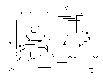
Fig. 1 shows a first embodiment of an inventive lacquering
device 10. On the frame 11 the channel 12 for the precoating
step and the protective ring 22 of the spinning station 13 as
well as the supports 14 and 15 for the linear transport device
16 are connected. At the movable part of the linear transport
device 16 the rotating motor 17 and at its shaft 18 the
turntable 19. The substrate 20 is connected to the plate
holding device 19, for example, by vacuum. For this purpose,
the holding device 19 is provided with respective vacuum bores,
not represented in the drawing. In the context of the present
3b

21~S0~9
other holding devices known to a person skilled in
the art can be used.
The open channel 12 with the capillary slot 21 for
the prelacquering step is represented in cross-
section in Fig. 1 and is further represented in
Fig. 2, also in section, in a perspective view.
Adjacent to the prelacquering device the
protective ring 22 for the spinning process is
arranged. It is connected to one or more stands
23 and 24 which can automatically adjust the
height position of the protective ring 22. For
example, they may be pneumatically adjustable
units, but also other devices, known to a person
skilled in the art. For the spinning process the
protective ring 22 is vertically upwardly
displaced with one or more stands 23 and 24, until
the protective ring 22 surrounds the substrate in
zo a suitable manner. In Fig. 2 the substrate to be
lacquered is shown above the protective ring 22
connected to the turntable 19 and the motor shaft
18. This position is represented in Fig. 1 in a
dash-dotted line and illustrates the situation
before or after the spinning process in which the
substrate is connected to the linear transport
device 16 in a position predetermined for the
spinning process the protective ring 22 however in
this position has not yet been displaced upwardly
or has already been lowered. This upward and
downward movement of the protective ring 22 is
necessary so that it does not obstruct the
substrate during its horizontal transport with the

linear transport device 16.
Fig. 1 shows the protective ring 22 in cross-
section. Its cross-section has a slanted U-shaped
profile. This embodiment ensures that the lacquer
or coating medium spun across the edge of the
substrate is caught within the annular profile and
is guided downwardly to the inner edge of the
protective ring 22 from where it is removed
completely from the inventive device with a
lacquer removal 25.
For a fully automated version of the coating
device automatic loading and unloading stations
are provided in the areas indicated respectively
at 26 and 27 in Fig. 1. The loading device
removes the substrate 20 to be lacquered from a
magazine connected to the coating device at an
appropriate location and transfers it onto the
plate holding device 19. The unloading device
receives the substrate 20 from the holding device
19 and places it into a magazine provided at a
suitable location.
Mode of operation of the lacquerinq device:
In a first step a substrate 20 is automatically or
manually connected to the turntable 19. The
turntable at this moment is in the area which is
indicated by reference numeral 26 in Fig. 1.
Subsequently, the linear transport device 16 is
moved in the direction of arrow 28, i.e., in
direction toward the channel 12.

-~ ~15~S063
As soon as the leading point of the substrate 20
reaches the upper edge of the capillary slot 21,
prelacquering begins. Of course, the substrate 20
is moved across the capillary slot 21 of the
channel 12 during the step of prelacquering.
After completion of the precoating step the
substrate 20 is moved together with the turntable
19, the motor 17, and the drive shaft 18 in the
direction of arrow 28 until it is centered above
the protective ring 22 which is at this moment in
its lowered rest position. When the substrate 20
has reached this position, the protective ring 22
is moved upwardly until the substrate 20 is
surrounded by it in a suitable manner. Then the
spinning process starts with which the lacquer
layer thickness on the substrate is made more
uniform and thinner. The excess lacquer is spun
off into the protective ring 22 and is removed via
the lacquer removal 25.
After comp]etion of the spinning process the
protective ring 22 is again lowered. The
substrate 20 is subsequently transported by the
transport device 16 into the area shown at 27 in
Fig. 1 where it is automatically or manually
removed from the turntable 19.

Dessin représentatif
Une figure unique qui représente un dessin illustrant l'invention.
États administratifs

2024-08-01 : Dans le cadre de la transition vers les Brevets de nouvelle génération (BNG), la base de données sur les brevets canadiens (BDBC) contient désormais un Historique d'événement plus détaillé, qui reproduit le Journal des événements de notre nouvelle solution interne.

Veuillez noter que les événements débutant par « Inactive : » se réfèrent à des événements qui ne sont plus utilisés dans notre nouvelle solution interne.

Pour une meilleure compréhension de l'état de la demande ou brevet qui figure sur cette page, la rubrique Mise en garde , et les descriptions de Brevet , Historique d'événement , Taxes périodiques et Historique des paiements devraient être consultées.

Historique d'événement

Description Date
Inactive : Périmé (brevet - nouvelle loi) 2013-08-26
Lettre envoyée 2011-01-11
Inactive : Transferts multiples 2010-12-17
Inactive : Correspondance - TME 2010-08-10
Inactive : CIB de MCD 2006-03-12
Lettre envoyée 2000-01-10
Inactive : Transferts multiples 1999-11-25
Inactive : Transfert individuel 1999-11-25
Accordé par délivrance 1999-06-01
Inactive : Page couverture publiée 1999-05-31
Préoctroi 1999-01-27
Inactive : Taxe finale reçue 1999-01-27
Un avis d'acceptation est envoyé 1998-11-27
Lettre envoyée 1998-11-27
Un avis d'acceptation est envoyé 1998-11-27
Inactive : Renseign. sur l'état - Complets dès date d'ent. journ. 1998-11-25
Inactive : Dem. traitée sur TS dès date d'ent. journal 1998-11-25
Inactive : CIB attribuée 1998-11-23
Inactive : CIB en 1re position 1998-11-23
Inactive : Approuvée aux fins d'acceptation (AFA) 1998-11-10
Toutes les exigences pour l'examen - jugée conforme 1995-12-12
Exigences pour une requête d'examen - jugée conforme 1995-12-12
Demande publiée (accessible au public) 1995-03-02

Historique d'abandonnement

Il n'y a pas d'historique d'abandonnement

Taxes périodiques

Le dernier paiement a été reçu le 1998-07-09

Avis : Si le paiement en totalité n'a pas été reçu au plus tard à la date indiquée, une taxe supplémentaire peut être imposée, soit une des taxes suivantes :

  • taxe de rétablissement ;
  • taxe pour paiement en souffrance ; ou
  • taxe additionnelle pour le renversement d'une péremption réputée.

Les taxes sur les brevets sont ajustées au 1er janvier de chaque année. Les montants ci-dessus sont les montants actuels s'ils sont reçus au plus tard le 31 décembre de l'année en cours.
Veuillez vous référer à la page web des taxes sur les brevets de l'OPIC pour voir tous les montants actuels des taxes.

Titulaires au dossier

Les titulaires actuels et antérieures au dossier sont affichés en ordre alphabétique.

Titulaires actuels au dossier
HAMATECH APE GMBH & CO. KG
STEAG MICRO-TECH GMBH STERNENFELS
Titulaires antérieures au dossier
EBERHARD MUHLFRIEDEL
KARL APPICH
MARTIN KALLIS
Les propriétaires antérieurs qui ne figurent pas dans la liste des « Propriétaires au dossier » apparaîtront dans d'autres documents au dossier.
Documents

Pour visionner les fichiers sélectionnés, entrer le code reCAPTCHA :


Pour visualiser une image, cliquer sur un lien dans la colonne description du document (Temporairement non-disponible). Pour télécharger l'image (les images), cliquer l'une ou plusieurs cases à cocher dans la première colonne et ensuite cliquer sur le bouton "Télécharger sélection en format PDF (archive Zip)" ou le bouton "Télécharger sélection (en un fichier PDF fusionné)".

Liste des documents de brevet publiés et non publiés sur la BDBC .

Si vous avez des difficultés à accéder au contenu, veuillez communiquer avec le Centre de services à la clientèle au 1-866-997-1936, ou envoyer un courriel au Centre de service à la clientèle de l'OPIC.

({010=Tous les documents, 020=Au moment du dépôt, 030=Au moment de la mise à la disponibilité du public, 040=À la délivrance, 050=Examen, 060=Correspondance reçue, 070=Divers, 080=Correspondance envoyée, 090=Paiement})


Description du
Document 
Date
(aaaa-mm-jj) 
Nombre de pages   Taille de l'image (Ko) 
Description 1998-10-13 8 346
Revendications 1998-10-13 3 109
Dessins 1998-10-13 3 42
Abrégé 1995-03-01 1 48
Description 1995-03-01 6 284
Revendications 1995-03-01 1 45
Dessins 1995-03-01 3 40
Dessin représentatif 1999-05-25 1 7
Dessin représentatif 1998-07-19 1 8
Avis du commissaire - Demande jugée acceptable 1998-11-26 1 163
Courtoisie - Certificat d'enregistrement (document(s) connexe(s)) 2000-01-09 1 115
Correspondance 1999-01-26 1 34
Taxes 2001-07-29 1 31
Taxes 1997-07-28 1 44
Taxes 1998-07-08 1 35
Taxes 1999-08-01 1 31
Taxes 2000-08-02 1 32
Correspondance 2010-08-09 1 47
Correspondance 2011-01-10 1 23
Correspondance 2011-01-10 1 24
Taxes 1996-07-22 1 39
Taxes 1995-12-11 1 61
Demande d'entrée en phase nationale 1995-12-11 6 185
Correspondance de la poursuite 1995-12-11 17 725
Courtoisie - Lettre du bureau 1995-12-11 1 29
Rapport d'examen préliminaire international 1995-12-11 29 1 071
Courtoisie - Lettre du bureau 1996-03-06 1 26
Correspondance de la poursuite 1998-08-26 2 54
Demande de l'examinateur 1998-06-01 1 31
Correspondance de la poursuite 1998-04-14 2 50
Demande de l'examinateur 1998-03-16 1 32
Correspondance de la poursuite 1997-12-15 4 149
Demande de l'examinateur 1997-10-16 2 101
Correspondance de la poursuite 1996-02-26 2 43
Correspondance de la poursuite 1997-12-15 4 115