Note : Les descriptions sont présentées dans la langue officielle dans laquelle elles ont été soumises.
21 72309
Field of the Invention
The present invention pertains to a flexible, fabric
type roll-up door assembly including a unique bottom bar
breakaway connection, tensioning and counterbalance spring
arrangement and door edge guide configuration.
R~ck~ound of the l,-vc~Lion
So-called roll or roll-up type doors are widely used
in industrial applications to close off sections of
industrial buildings or to seal a doorway which opens to the
exterior of the building. Such doors are typically
characterized by a flexible, fabric curtain type closure member
supported on a rotatable shaft wherein the side edges of the
closure member are disposed in opposed guideways on opposite
sides of the doorway and the door is controlled for rapid opening
and closing action. Since such doors are often used in
facilities wherein there is a substantial amount of traffic
through the doorway, releasable or so-called breakaway
connections have been developed to permit the door closure member
21 72309
~-to be released from the guideways if struck by a vehicle traversing
the doorway to prevent or reduce damage to the door, the vehicle
or injury to personnel exposed to such incidents. Other features
which have been considered desirable for roll-up doors include a
5 support frame which reduces the space occupied along each side of
the doorway, ease of erection and assembly of the door at the site
and a door actuating me~-hAn;sm which does not exert the full force
or torque of the drive motor on the door bottom edge, in the event
that an object is in the doorway when the door moves to a closed
10 position.
There have been several developments in breakaway
connection devices between opposed sides of a roll-up door at the
bottom edge and the door guideways. Many of these connection
devices are relatively complex and require a substantial amount of
15 time to reconnect the door to the guideways and the door actuating
mechAnism if the breakaway connection is released. Prior art door
breakaway connections include types wherein a pivoting latch member
is held in position by a detent member and pivots or releases from
the detent to permit operation of the breakaway connection. Other
20 types of breakaway connections include frangible pin type connec-
tions which must be replaced once the breakaway connection has
actuated.
Roll-up type doors are also typically adapted to be
actuated in such a way that the door closure member is always under
25 tension in order to keep the flexible fabric in a relatively stiff
operating condition to provide proper functioning of the door.
Relatively complex cable and travelling weight mechanisms have been
developed for tensioning the door and counterbalancing the weight
of the door. Somewhat complicated counterbalance spring arrange-
30 ments have been developed which are disposed within the door rollsupport shaft or drum.
Accordingly, there has been a need to develop a breakaway
connection which is mechanically uncomplicated, reliable in
operation and provides for relatively easy reconnection of the door
35 bottom bar or bottom edge to the door traversing mechanism and
guideway. There has also been a need to improve the door side edge
seals to provide for a substantially weather-tight seal at the
2 1 72309
~doorway. Still further, a need has existed for improvements in the
mechanism which provides for tensioning the door bottom edge under
all operating conditions. The present invention provides solutions
to the above-mentioned problems associated with roll-up doors as
5 well as providing other advances in the art of such doors.
SummarY of the Invention
The present invention provides a roll-up type door or
barrier including a unique releasable connection between the door
10 bottom edge and opposed door guideways, an improved door tensioning
mechanism, unique door side edge guideways, improved wind bar
deployment mech~n;sm and a unique counterbalance mech~n;sm.
In accordance with one important aspect of the invention,
a releasable, "breakaway" type connection is provided between a
15 transverse door bottom beam or bar and opposed guideways for the
door side ed~es wherein opposed, movable latch members are
releasably engageable with opposed slide members disposed in the
guideways and normally attached to the door through the bottom bar
and latch members for tensioning the door closure member.
In one preferred embodiment of the breakaway connection,
the latch members comprise movable bar or fin type members which
are disposed in cooperating slots formed in the slide members. The
latch members include projections which may be engaged with
reentrant edges formed in the slots to hold the latch members in
25 engagement with the slide members. The latch members are spring
biased to tend to move out of the slots to retract in response to
a force exerted on the latch members which tends to rotate the
slide members in the guideways.
In another embodiment of the breakaway connection, the
30 latch members are biased into the slots in the slide members and
the slide members are provided with projections which cooperate
with elongated keyways in guide members forming the guideways. In
response to a force tending to separate the latch members from the
slide members, the slide members undergo limited rotation to allow
35 the latch members to exit the slots.
In accordance with yet another embodiment of the
breakaway connection, the latch members are formed as projecting
2~ 72309
portions on the slide members which are disposed in cooperating
slots formed in a transverse bottom beam connected to the door
closure member. In response to a force acting on the door, the
latch members and slide members rotate in the guideways to
5 disengage from the bottom beam.
The present invention also provides preferred embodiments
of a breakaway connection between the door bottom bar and the
opposed guideways wherein the latch members and the slide members
have cooperating hook surfaces and retaining pins, respectively,
10 which maintain the latch members connected to the slide members and
the latch members and slide members have cooperating cam surfaces
which, in response to a breakaway force exerted on the door, effect
limited relative movement between the latch members and the slide
members to disengage the latch members from the slide members and
15 to bias the latch members into their retracted positions completely
disengaged from the slide members.
In accordance with another important aspect of the
invention, a roll-up type door is provided with an improved
tensioning mech~nism including opposed cable reels disposed on the
20 door support shaft and outboard of the opposite side edges of the
door closure member. The reels are each connected to a tensioning
cable and slider assembly disposed in opposed guideways and the
reels include spiral power tensioning springs disposed therein for
applying a predetermined tension to the door closure member via the
25 cable and slide assemblies and for acting as counterbalance springs
during unrolling of the door. The unique reel construction may be
modified to form a secondary counterbalance mechanism which may be
operably connected to the door closure member through a chain and
sprocket drive and wherein the sprockets may be interchanged to
30 vary the counterbalance effect.
Moreover, the tensioning reel and cable arrangement,
together with the connection between the door and the slide members
connected to the tensioning cables, provides a pulldown force on
the door which is determined by the spring bias on the reels and
35 is not the result of the maximum door drive motor effort. In this
way, if an obstruction is struck by the door during closing
thereof, and obstruction sensing devices are not activated, a
2 ~ 72309
~ reduced force is exerted on the obstruction to mln;m; ze damage
thereto or to the door itself.
In accordance with another important aspect of the
invention, a roll-up type door is provided with a movable barrier
bar to m;n;m;ze deflection of the door closure member or
"curtain" due to wind and other pressure generating forces acting
thereon which bar is moveable to selected working positions by a
unique cable and takeup reel arrangement supported on the door
closure member support shaft.
Still further, the present invention provides unique
side edge guide members for a roll-up type door which include
side edge seal means for providing a substantially weathertight
seal along the side edges of the door closure member and for
supporting a door tensioning slide member for traversal along the
guideways in an improved and uni~ue manner.
The above-mentioned guide members and support frames
minimize the space occupied by the door adjacent a doorway and
m;n;m;ze floor space occupied by the guide structure. Moreover,
the opposed guide members, together with an assembly comprising
the door drive motor, the closure support shaft, the closure
member and the closure member tensioning mechanism may be easily
transported and assembled at the site of installation of the
door.
Broadly stated, the invention is a roll-up door for
forming a barrier across a doorway comprising; rotatable shaft
means having a flexible closure mounted thereon to be rolled and
unrolled to form a movable closure for said doorway; spaced apart
guide means disposed generally at opposite sides of said doorway;
and latch means disposed at opposite sides of a bottom edge of
said closure for latching said closure to respective ones of said
guide means for linear traversal along said guide means, said
latch means comprising a first member supported by said guide
means for traversal therealong and a second member supported on
said closure and cooperable with said first member to releasably
latch said bottom edge of said closure to said guide means, one
of said members comprising a latch member projecting into a slot
formed in the other of said members, cooperating retaining means
on said members of said latch means, respectively, for latching
said closure to said guide means, said latch means being operable
21 72309
to provide disconnection of said bottom edge of said closure from
said guide means in response to a force acting on said closure
generally transversely with respect to the plane of said closure
whereby at least one of said members of said latch means
undergoes one of limited rotation and linear translation with
respect to the other member in response to said force to effect
disconnection of said bottom edge of said closure from said guide
means. - -
The above-mentioned features together with other
important aspects of the present invention will be further
appreciated by those skilled in the art upon reading the detailed
description which follows in conjunction with the drawing.
Brief Descri~tion of the Drawin~
FIGURE 1 is a front elevation of a roll-up door in
accordance with the present invention;
FIGURE 2 is a detail view taken generally from the line
2-2 of FIGURE l;
FIGURE 3 is a detail front elevation of the upper and
lower portions of the door assembly;
FIGURE 4 is a detail view taken generally from the line
4-4 of FIGURE 3;
2 t 72309
FIGURE 5 is a view taken generally from the line 5-5 of
FIGURE 3;
FIGURE 5A is a section view taken generally from line 5A-
5A of FIGURE 5;
FIGURE 6 is a section view taken generally from the line
6-6 of FIGURE 3;
FIGURE 7 is a cutaway perspective view of one of the
slide member and latch assemblies;
FIGURE 8 is a longitudinal section view taken generally
10 along the line 8-8 of FIGURE 7;
FIGURE 8A is a section view taken generally from the line
8A-8A of FIGURE 8;
FIGURE 8B is a section view taken generally from the line
8B-8B of FIGURE 8;
FIGURES 9A, 9B and 9C are views showing the action of the
latch member ~shown in FIGURE 8 as it disengages from the slide
member;
FIGURE 10 is a view taken generally from the line 10-10
of FIGURE 2 showing a counterbalance device for the door closure
20 member;
FIGURE 11 is a section view taken generally from the line
11-11 of FIGURE 10;
FIGURE 12 is a longitudinal section view taken generally
along the same line as the view of FIGURE 8 showing a first
25 alternate embodiment of a breakaway connection latch member and
slide member;
FIGURES 13A and 13B are views showing the action of the
embodiment of FIGURE 12;
FIGURE 14 is a section view similar to the section views
30 of FIGURES 8 and 12 showing a second alternate embodiment of a
breakaway connection in accordance with the invention;
FIGURE 15 is a section view taken generally from the line
15-15 of FIGURE 14;
FIGURE 16 is a perspective view of a third alternate
35 embodiment of a breakaway connection in accordance with the
lnvention;
2 1 723û9
FIGURE 17 is a perspective view of a fourth alternate
embodiment of a breakaway connection in accordance with the
invention;
FIGURE 18 is a perspective view of the latch member for
5 the breakaway connection of the embodiment of FIGURE 17;
FIGURE 19 is a front elevation of the slide member of the
embodiment of FIGURE 17;
FIGURE 20 is a section view taken generally from the line
20-20 of FIGURE 19; and
FIGURE 21 is a section view taken from the line 21-21 of
FIGURE 19.
Description of the Preferred Embodiments
In the description which follows, like elements are
15 marked throughout the specification and drawing with the same
reference nume~rals, respectively. The drawing figures are not
necessarily to scale and certain features may be shown exaggerated
in scale or in somewhat schematic form in the interest of clarity
and conciseness.
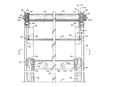
Referring primarily to FIGURES 1 and 3, the roll-up door
of the present invention is illustrated and generally designated
by the numeral 20. The door 20 is characterized by opposed
generally vertically extending frame members 22 and 24 which extend
along both sides of an opening or doorway 26 formed in a wall 27
25 for which the door is to form a closure or barrier. Opposed
support brackets 28 and 30 are disposed at the top of the frame
members 22 and 24 and are adapted to support a rotatable shaft 32,
FIGURE 3, comprising a spool on which a flexible curtain type door
closure member 34 is wound in a conventional manner. The brackets
30 28 and 30 include suitable bearing means 33, one shown, for
supporting opposed reduced diameter shaft portions 32a and 32b of
the shaft 32. The door closure member 34 may comprise a plastic
impregnated fabric or the like or a similar flexible structure
which is capable of being wound onto and unwound from the shaft or
35 spool 32. A generally channel-shaped headplate or hood 38 extends
between and is suitably secured to the support brackets 28 and 30,
see FIGURE 2, also.
21 72309
-
As shown in FIGURES 1 and 2, the shaft 32 is operable to
be rotated in opposite directions by a reversible motor and gear
reduction unit 40 which is mounted on the support bracket 30 and
has a power output shaft 42, FIGURE 2, drivingly connected to an
5 endless chain 44 which is trained over sprockets 46 and 48. The
sprocket 48 is suitably connected to the shaft end 32b for rolling
and unrolling the door closure member 34. The motor unit 40 is
adapted to be operated at will by suitable operator controls, not
shown, and automatically controlled to stop in the event of the
10 door closure member 34 striking an obstruction or the like as will
be explained in further detail herein. The motor unit 40 may also
incorporate an integral operator controllable brake mechanism, not
shown, which is automatically energized to prevent rotation of the
motor output shaft 42 when the motor unit is deenergized. The
- 15 brake meçh~nicm may be manually released, at will. The motor unit
40 may be of a type commercially available such as from U.S.
Electrical Motor Div. of Emerson Electric Co., St. Louis, Mo.
The assembly of the headplate or hood 38, together with
the opposed support brackets 28 and 30, is adapted to be bolted to
20 the opposed frame members 22 and 24 by suitable fastener means 39,
see FIGURES 2 and 10, by way of example. Accordingly, the assembly
of the shaft or spool 32 and all of the components supported by the
shaft and the brackets 28 and 30 may be separately assembled and
connected to the frame members 22 and 24, either before or after
25 these frame members have been erected at the site of installation
of the door 20, such as at the doorway 26.
Referring now to FIGURES 3 and 4, the shaft portions 32a
and 32b are adapted to support spaced apart cable reels 52 and 54,
which reels are keyed to the respective shaft portions by suitable
30 key means 56, FIGURE 4. Each of the reels 52 and 54 has an
elongated cable 58 trained thereover and descending through the
frame members 22 and 24, respectively, for supporting an elongated
transversely ext~;ng door support or windbar 60. Opposite ends
of the windbar 60, see FIGURE 3, have grooved bosses 62 formed
35 thereon and disposed in a guideway 63, see FIGURE 4, formed by the
opposed frame members 22 and 24. As shown by example in FIGURE 4,
each of the cables 58 is trained over its respective support reel
2 1 72309
52 or 54, over an idler roller 55, around the boss 62 and is
secured at its distal end to the upper end of the frame members 22
and 24, respectively. As the door closure member 34 is unwound
from the shaft 32 to descend toward the floor 21, FIGURE 3, the
5 windbar 60 may descend approximately half the distance from the
shaft 32 to the closure member bottom edge, indicated generally at
35, to provide support for the closure member to resist billowing
in the event of a substantial pressure differential acting through
the opening in a direction toward the side of the opening at which
lo the door 20 is disposed. Alternatively, the windbar 60, the cables
58 and guide pulleys 55 may be disposed in guideways 65, one shown
in FIGURE 4, formed by the frame members 22 and 24, if the pressure
forces act in the opposite direction.
Referring further to FIGURE 3 and also FIGURE 5, the door
15 20 includes a unique tensioning mechanism for maintaining the
closure membe~ 34 substantially taut during movement and in a
closed as well as rolled up condition, which mechanism is charac-
terized by spaced apart tensioning reels 70 and 72 which are
mounted on the shaft portions 32a and 32b outboard of the windbar
20 cable reels 52 and 54, as shown. Elongated flexible cables 74 are
trained around and secured to the reels 70 and 72, respectively,
descend along the frame members 22 and 24 and are trained around
respective pulleys 78 disposed at the bottom of the frame members
22 and 24, respectively. The distal ends of the cables 74 are
25 connected to generally cylindrical slide members 80 which, in turn,
are releasably connected to the door closure member 34, generally
at its bottom transverse edge 35 for tensioning the closure member
as mentioned previously. The slide members 80 comprise part of a
unique latch me~h~n;sm to be described below, other parts of which
30 are mounted on a substantially stiff transverse beam 82 ext~n~ing
across and defining the bottom edge 35 of the door and suitably
secured to the flexible closure member 34 at 79, see FIGURE 7.
Referring now to FIGURES 5 and 5A, certain details of the
reel 72 are illustrated. The reel 70 is identical to the reel 72.
35 The reel 72 includes a hub 84 mounted on the shaft portion 32b and
suitably keyed thereto for rotation with the shaft 32. The hub 84
also supports a generally cylindrical case 86 which is rotatable
21 72309
relative to the hub. The case 86 includes a cable drum 88 on which
a cable 74 is secured and adapted to be wound thereon. A generally
spiral band type spring 90 is disposed in the case 86 and is
secured to the drum 88 at one end 92 and to the hub 84 at an
5 opposite end 94, as illustrated. The spring 90 may be pretensioned
so that it has a tendency to wind the cable 74 onto the drum 88 by
rotating the case 86 in a counterclockwise direction, viewing
FIGURE 5. When the door closure member 34 is unwound from the
shaft 32 in a counterclockwise direction, viewing FIGURE 5, the
10 shaft 32 will tend to turn more revolutions as the closure member
is unwound since the diameter of the hub 88 is greater than the
maximum diameter of the rolled up closure member 34. In this way,
the spring 90 tends to be wound tighter increasing the tension on
the cable 74 and closure member 34 and acting to counterbalance the
15 weight of the closure portion of the member 34 which becomes
unreeled from ~the shaft 32.
Referring further to FIGURE 5, each of the reels 70 and
72 is provided with a unique braking mechanism to minimize rapid
rotation of the case 86 in the event of a disconnection between the
20 slide members 80 and the bottom beam 82. Each brake mech~n;sm
comprises an arm 98 pivotally mounted about a pivot pin 100
suitably secured to the support bracket 28 or 30, respectively.
A rotatable sheave 102 is supported on one end of the brake arm 98
over which the cable 74 is trained, as illustrated. A brake shoe
25 104 is mounted on the brake arm 98 between the sheave 102 and the
pivot pin 100. The arm 98 includes a distal projecting end portion
99 extending in a direction from the pivot 100 opposite the
direction of the sheave 102 and supports a counterweight 108.
Tension in the cable 74 maintains the brake arm 98 in a position
30 where the brake shoe 104 is clear of the drum 88. When the door
bottom beam 82 becomes disconnected from the slide members 80, the
reels 70 and 72 will tend to rotate rapidly, however, relaxation
of the cables 74 will allow the brake arms 98 to pivot about their
pivot pins 100 to engage the brake shoes 104 with the respective
35 reels to at least reduce the speed of rotation so that the slide
members 80 move down to the bottom of the frame members 22 and 24
at substantially reduced speed.
--10--
21 72309
Referring now to FIGURES 6 and 7, each of the frame
members 22 and 24 comprises a generally U-shaped beam or channel
section having opposed flanges 23 and 25, respectively. A unique,
elongated guide member 112 is mounted within and suitably connected
5 to each of the frame members 22 and 24, respectively, as illustrat-
ed in FIGURE 6, by suitable fastener means, not shown. The guide
member 112 is characterized, preferably, by an extrusion formed of
a suitable engineering material such as aluminum. Each guide
member 112 includes an elongated, generally cylindrical guideway
10 114 for slidably journalling the slide member 80. The guideway 114
is intersected by elongated, opposed slots 116 and 118, see FIGURE
7 also. The slot 116 is delimited by elongated parallel guide
surfaces 117 and 119 and the slot 118 is delimited by elongated,
opposed bosses 121 and 123 which are adapted to support elongated,
15 generally flat flexible seal strip members 124 and 126, respective-
ly. The seal strips 124 and 126 are preferably formed of a
suitable elastomer. The seal strips 124 and 126 provide a
substantial weather-tight seal for the door closure 34 along its
opposed longitudinal side edges at the frame members 22 and 24.
20 A transverse web 128 is formed in the guide member 112 and
partially defines an elongated cableway 130 through which a run 75
of the cable 74 is trained.
As further shown in FIGURES 6 and 7, the opposite
longitudinal side edges 129 and 131 of the closure member 34 extend
25 between and are engaged by the seal strips 124 and 126, respective-
ly. Each of the slide members 80 is adapted to be disposed in its
respective guideway 114 for sliding movement therealong. However,
each of the slide members 80 has a transverse, generally rectangu-
lar boss or key portion 81 which is adapted to be disposed in the
30 slot 116 and engageable with the guide surfaces 117 and 119 to
orient the guide member in the guideway. As will be appreciated
from the foregoing description, the guide members 112, due to their
placement between the channel flanges 23 and 25, partially define
the guideways 63 and 65 for the windbar 60. The guide surfaces 117
35 and 119 are disposed on opposed substantially cantilever beam
portions 125 and 127 of the guide 112, which beam portions may be
elastically deflected to allow the guide surfaces 117 and 119 to
2t 72309
move relative to each other for a purpose to be described hereinbe-
low. As shown in FIGURE 8, the distal end of cable 74 includes a
becket 77 secured in a stepped bore 85 in the slide member 80,
which bore is intersected by a narrow slot 87 of less width than
5 the diameter of the becket.
Referring now to FIGURES 3, 7 and 8, the beam 82 is
adapted to support opposed substantially stiff, rectangular plate
shaped latch members 134 which project into cooperating generally
rectangular slots 136, FIGURE 8, formed in the slide members 80,
10 respectively, and opening to the transverse bottom side 83 thereof.
Each latch member 134 is connected to a generally rectangular cross
section plunger 138, FIGURE 8, slidably supported in a cooperating
rectangular cross section bore 140 formed in a support housing 142.
As shown in FIGURE 8, the support housing 142 may be fabricated of
15 opposed housing sections 144 and 146 which are suitably fastened
together by conventional mec-h~n;cal fasteners 138, for example.
As shown in FIGURES 8A and 8B, by way of example, the plunger 138
is engaged with a coil spring 150 disposed in the bore 140 and
supported against an end wall 141 of the housing 142. The plunger
20 148 includes an elongated stem 149 which projects through a
suitable bore formed in an end wall 143 and is engageable with an
actuator 152 of a suitable electrical switch 154. Each plunger 138
has a stem 149 operable to engage and disengage an actuator 152 of
a switch 154. If a latch member 134 becomes disengaged from a
25 slide member 80, the plunger 138 is biased to move in a direction
to cause the stem 149 to engage the switch actuator 152 allowing
the switch 154 to effect immediate shutoff of the drive motor 40
to arrest movement of the closure member 34.
As shown in FIGURE 8B, the distal end of the latch member
30 134 is provided with retaining means comprising opposed lateral
projections 135 which extend the full width of the latch member,
as shown, and are engageable with cooperating retaining means
comprising projections defined by reentrant edges 137 of the slot
136. The slot 136 is also defined by opposed laterally projecting
35 jaw portions 139 of the boss 81. The projections 135 and reentrant
edges 137 cooperate to retain the latch member 134 in the slot 136
during normal operation of the door closure member 34. Although
-12-
21 72309
the slot 136 is open at the bottom transverse end 83 of the slide
member 80, the slide member is tensioned by the cable 74 to move
downwardly in the guide member 112, thus always retaining its
engagement with the latch member 134 except under circumstances to
5 be described herein.
As shown in FIGURES 8A and 8B, the plunger 138 has a
manual actuating bolt or arm 160 pivotally connected to the plunger
by a suitable pivot pin 162. The actuator arm 160 projects through
an elongated J-slot 164 formed in the housing 142 and the actuator
10 arm also projects through a co-extensive J-slot 166 formed in the
sidewall of the beam 82, FIGURES 7 and 8A. As shown in FIGURE 8A,
the beam 82 is provided with opposed sidewalls 170 and 172 and one
or more transverse webs 174 for supporting the housing 142. In the
view of FIGURE 8A, the J-slot 166 is formed in the sidewall 170
15 aligned with and coextensive with the J-slot 164. The actuator arm
160 of each pl~unger 138 may be used to extend the latch member 134
to engagement with the slide member 80. The latch members 134 may
be held in their extended positions during connection of the latch
members to the slide members 80 against the bias of their respec-
20 tive springs 150 by moving the respective actuator arms 160 downinto the base portions 165, FIGURE 8A, of the respective J-slots
164. Actuator arms 160 may be provided projecting from each side
of beam 82, if desired.
The tension on the cables 74 urge the slide members 80
25 to move downward in the guideways 114 toward the sheaves 78 at all
times during normal operation of the door 20. Accordingly, tension
is maintained in the closure member 34 at all times in its rolled
up, full open position as well as in its closed position. In fact,
as earlier described, the tension increases as the closure member
30 34 is pulled to its closed position with the bottom beam 82 engaged
with floor surface 21. However, the motor 40, being drivably
engaged with the shaft 32 does not exert its full driving torque
on the beam 82 since it is merely acting to roll and unroll the
closure member by rotation of the shaft 32. Accordingly, only the
35 tension of the cable 74 substantially urges the beam 82 downward
toward the floor 21. In this way, any obstruction in the doorway
26 struck by the beam 82 during operation of the closure member 34,
-13-
21 72309
assuming that all obstruction sensors should fail, will only urge
the beam downward with substantially the force of the tensioning
cables 74 since the flexible closure member 34 would easily buckle
during unrolling thereof if the beam 82 were prevented from
5 downward movement.
If the closure member 34 is struck by a vehicle or person
moving through the doorway, it should be allowed to disconnect from
the guides 112 to minimize damage to the door 20 and any object
striking the door. Accordingly, if a predetermined force,
10 generally normal to the plane of the closure member 34, should
strike the closure member and/or the bottom beam 82, the latch
members 134 will tend to rotate the slide members 80 about their
longitudinal axes, which axes coincide with the cable bores 85,
formed in the slide members.
The action which will cause the latch members 134 to
disengage from~the slide members 80 is illustrated for one of the
latch members by way of example in FIGURES 9A through 9C. The beam
82 is eliminated from FIGURES 9A through 9C for clarity. Referring
to these figures, FIGURE 9A shows the latch member 134 engaged with
20 the slide member 80 in the normal working position. The reentrant
edges 137 cooperate with the projections 135 on the latch member
134 to retain the latch member in engagement with the slide member
80. Moderate forces exerted in the directions of the arrow 151 in
FIGURE 9A may cause slight rotation of the slide member 80 about
25 its longit~l~;n~l central axis but will not cause disengagement of
the latch member 134 from the slide member. However, when a
predetermined force is exerted on the door closure member 34 or the
bottom beam 82, the slide member 80 will be rotated to the position
shown in FIGURE 9B wherein, as shown, the orientation of the slot
30 136 is such that the latch member 134 may exit from the slot as the
projections 135 disengage from the reentrant edges 137. Moreover,
the key portion 81 may be dimensioned such that one of the jaws 139
will tend to elastically deflect to widen the portion of the slot
136 between the reentrant edges 137 as the jaw forcibly engages the
35 beam portion 127, for example. Moreover, the elasticity of the
beam portion 127 can result in some deflection of the beam near the
surface 119 to permit some further rotation of the slide member 80.
-14-
?1 72309
The above described rotation will be sufficient to allow the latch
member 134 to disengage from the slide member 80 and retract toward
the housing 142 under the urging of the spring 150. FIGURE 9C
shows the disengaged condition of the latch member 134 with respect
5 to the slide member 80. When complete disengagement occurs, the
slide member 80 will return to its normal working position as the
beam portions 125 or 127 tend to recenter or reorient the slide
member in its working position. The latch members 134, when
disengaged from the slide members 80, advantageously retract toward
10 the housings 142 to minimize any damage to the latch members which
might occur from striking an obstruction in the doorway 26.
As previously mentioned, when the latch members 134
disengage from the guide members 80, the stems 149 will effect
actuation of the switches 154 to shut off the motor drive unit 40,
15 immediately arresting movement of the door closure member 34.
Moreover, as previously described, the reduced tension in the
cables 74 will cause the brake arms 98 to pivot into a position to
effect braking action against the tensioning reels 70 and 72. The
switches 154 are, preferably, connected in series so that actuation
20 of either of one of the switches, should only one latch member
become disengaged, will still effect shutoff of the motor drive
unit 40.
Referring now to FIGURES 10 and 11, there is shown a door
counterbalance device which may be mounted on the frame bracket 28
25 and is similar in some respects to the cable tensioning reels 70
and 72. The counterbalance device is generally designated by the
numeral 180 and is suitably supported on the bracket 28 by
conventional fasteners 182 as shown in FIGURE 11. The device 180
includes a generally cylindrical housing 190 having opposed side
30 plates 194 and 196, a peripheral rim 198 interposed between the
side plates and a spiral flat band-type spring 200 suitably keyed
to the rim 198 at 202. The opposite end of the spiral spring 200
is connected to a hub member 204 at a connection point 206. The
hub 204 is supported on and rotatable relative to the housing 190
3S and has a stub shaft part 208 projecting therefrom, on which is
mounted a conventional chain sprocket 210 suitably keyed to the
stub shaft by key means 212. As shown in FIGURE 10, the sprocket
2 ~ 72309
210 is drivably connected to a sprocket 214 by a conventional
endless chain 218. The sprocket 214 is mounted on shaft 32a and
suitably keyed thereto by key means 216. The spring 200 may be
suitably pretensioned to effect a driving force on the hub 204
5 which will tend to rotate the sprockets 210 and 214 in a clockwise
direction, viewing FIGURE 10, to aid in counterbalancing the weight
of the door closure member 34 when unreeled from the shaft 32. In
other words, as the shaft 32 rotates in a counterclockwise
direction, viewing FIGURE 11, to unroll the closure member 34,
10 spring tension increases in the spring 200. If this tension is
insufficient, the sprockets 210 and 214 may be interchanged with
sprockets of suitable pitch diameters, respectively, to effect a
torque effort on the sprocket 214 which provides a suitable
counterbalance effect on the shaft 32 by the device 180.
Referring now to FIGURE 12 and FIGURES 13A and 13B, a
first alternat,e embodiment of a breakaway latch connection between
the door beam 82 and a tensioning cable 74 is illustrated. In the
embodiment illustrated in FIGURES 12, 13A and 13B, a modified slide
member 280 is disposed in a guide member 282 similar to the guide
20 member 112 but having elongated longitudinally extending grooves
284 disposed in the opposed beam portions 125 and 127. In all
other respects, the guide 282 is virtually identical to the guide
112. As shown in FIGURE 13A, the slide member 280 has a longitu-
dinally extending latch member receiving slot 286 and opposed
25 longitudinal, radial outward projecting key portions 288 which are
operable to be disposed in the grooves 284 to allow the slide
member 280 to slide along the guide 282 in the same manner that the
slide 80 is operable in the guide 112.
As shown in FIGURES 12 and 13A, a modified latch member
30 290 extends into the slot 286. The latch member 290 is also
preferably a substantially stiff, generally rectangular plate
shaped element which is connected to a plunger 292 slidably
disposed in a bore 293 formed in a housing 294 similar to the
housing 142. The plunger 292 is also of generally rectangular or
35 square cross section to prevent rotation of the latch member 290.
A switch actuating stem 296 extends from the plunger 292 in a
direction opposite the latch member 290 and is engageable with the
-16-
21 72309
switch actuator 152. In the embodiment of FIGURE 12, the plunger
292 and the latch member 290 are biased in a direction opposite
that of the earlier described embodiment by a coil spring 298
disposed in the housing 294 and engaged with the plunger 292. A
5 suitable actuating arm 299 extends from the side of the plunger 292
in a manner similar to the arrangement of the actuating arm 160 for
the plunger 138.
In the operation of the latch connection shown in FIGURES
12, 13A and 13B, when a force sufficient to disconnect the latch
10 member 290 from the slide member 280 occurs, the iatch member will
tend to rotate the slide member 280 but will be resisted by the
projections 288 disposed in the grooves 284. However, when a
sufficient force is exerted on slide member 280 by the latch
member, the beam portions 125 and 127 will tend to deflect enough
15 to allow the projections 288 to move to the position shown in
FIGURE 13B. In this position, the slide member 280 has rotated
sufficiently to allow the latch member 290 to exit the slot 286 and
disconnect from the slide member and the guide 282 even though the
bias of the spring 298 is urging the latch member toward the slot.
The slide member 280 is also provided with a longitudinal
slot 287 which will permit some compressive action to occur on the
slide member as it tends to rotate its projections 288 out of the
grooves 284. The camming action of the projections 288 will tend
25 to effectively reduce the diameter of the slide member 280 to allow
the projections to exit the grooves 284 and assume the position
shown in FIGURE 13B. Accordingly, the flexing of the beam portions
125 and 127 and/or the flexing of the body of the slide member 280
itself will allow movement of the projections 288 out of the
30 grooves 284 to allow the slide member to assume the position shown
in FIGURE 13B.
One advantage of the arrangement illustrated in FIGURES
12, 13A and 13B is that the slide member 280 will tend to remain
in the position at which it disconnected from the latch member 290
35 due to the elastic gripping forces exèrted on the slide member when
the projections 288 have cammed out of the grooves 284 to the
position shown in FIGURE 13B. The slide members 280 will, of
21 72309
course, require repositioning so that the projections 288 extend
into the grooves 284 prior to reconnecting the latch members 290
with the slide members. Each of the latch members 290 may be
retracted by the aforementioned arm 299 so that the latch members
5 may be positioned adjacent the slots 286 and then the arms released
to allow the latch members to reengage with the slide members 280
once the slide members and the bottom beam 82 have been properly
positioned relative to each other to provide for reengagement of
the breakaway connections formed by the slide members and latch
10 members.
Referring now to FIGURES 14 and 15, there is illustrated
a second alternate embodiment of a breakaway connection for
connecting a bottom beam of a door closure member to guide members
282, one shown in FIGURES 14 and 15. In the embodiment of FIGURES
15 14 and 15, a modified slide member 380 is shown disposed in one of
the guides 282 between the beam portions 125 and 127 and having
elongated opposed radial outward projecting key portions 388
registrable in the grooves 284 as shown in FIGURE 15. The slide
member 380 has a longitudinally ext~n~;ng slot 387 formed therein
20 and is suitably attached to the cable 74 in a manner similar to the
embodiment shown in FIGURE 8. However, the slide member 380 has
a laterally projecting plate or fin like latch member 389 secured
thereto and projecting into a slot 390 formed in a transverse end
wall 392 of a modified closure member transverse bottom beam 394,
25 suitably connected to the door closure member 34 in a manner
similar to the embodiment of FIGURE5 1 through 8. The beam 394 is
also provided with a retractable bolt member 396, engageable with
the latch member 389 to transfer the pulldown effort of the cables
74 from the slide members 380 to the door closure member 34. Each
30 of the bolts 396, one shown, has a rectangular cross section shank
part 396a disposed in a suitable complementary bore 398 formed in
the beam 394 and biased by a spring 400 into the position shown in
FIGURES 14 and 15. Opposed actuator arms 402 and 404 are provided
projecting from opposite sides of the beam 394 and disposed in
35 suitable slots 406 to provide for manually retracting the boIt 396
so that the latch member 389 may be reinserted in the groove 390
when it becomes disengaged from the beam 394.
-18-
2 1 72309
In the operation of the embodiment of the breakaway
connection shown in FIGURES 14 and 15, if the door closure member
34 and/or the beam 394 are struck with a sufficient force, the beam
394 will urge the slide members 380 to rotate to cam the key
5 portions 388 out of the slots 284 by either elastically deflecting
the beam portions 125 and 127 and/or radially compressing the body
of the slide member 380, thanks to the provision of the slot 387.
Rotation of the slide member 380 will allow the latch member 389
to slide out of the slot 390 as the beam 394 tends to move in one
10 direction or another, as indicated by the double arrow 151.
Movement of the latch member 389 out of the slot 390 will, of
course, result in actuation of the switch 154 due to disengagement
of the actuator 152 from the distal end of the latch member 389 to
effect shutoff of the motor-drive unit 40. When it is desired to
15 reengage the beam 394 with the latch member 389, the slide member
380 is rotated~back to the position shown in FIGURE 15, the bolt
396 is retracted and the beam 394 is lowered to a position to allow
the latch member 389 to reenter the slot 390, which is open at the
lower side 395 of--the beam 394. The bolt 396 is preferably
20 provided with a sloping cam surface 397 which cooperates with a
sloping surface 399 formed on the latch member 389 to facilitate
automatic reengagement of the latch member into the slot 390 by a
camming action which effects retraction of the bolt 396 against the
bias of spring 400.
FIGURE 15 also illustrates sidewall extensions of the
slot 390 formed by cantilever wall portions 391 and 393 which are
each disposed at about a 45 angle to the plane of the normal
position of the latch member 389 and allow the latch member to
rotate sufficiently in the slot to exit the slot upon rotation of
30 the slide member 380 in the guide 282. However, the slide member
380 may be modified to eliminate the projections 388 and the slot
sidewalls 391 and 393 may be modified to extend generally parallel
to the plane of the latch member 389 as indicated-by numerals 391a
and 393a. These cantilever sidewalls may be configured to be
35 resiliently deflectable to allow the latch member 389 to undergo
rotation in the slot in response to a force acting on the beam 394
or the closure member 34 and of sufficient magnitude to effect
--19--
2 1 72309
rotation of the slide member 380 to a position such that the latch
member 389 will exit the slot 390. In other words, the resilient
bias forces which tend to position the latch member 389 in the slot
390 in the position illustrated in FIGURE 15 may be provided by the
5 projections 388 or by the cantilever wall portions 391a and 393a
of the slot 390.
Referring now to FIGURE 16, there is illustrated yet
another embodiment of a breakaway connection for the roll-up door
20 for guiding the bottom beam 82 between the guide members 112
10 while permitting release of respective latch members between the
beam and the guide members. FIGURE 16 shows one of the latch
members of the third alternate embodiment, generally designated by
the numeral 510. The latch member 510 is characterized as a
generally rectangular plate member which is secured to a plunger
15 138 in the same manner as the latch member 134 and is biased by a
spring 150 di~sposed in a housing 142. A slide member 511 is
connected to the cable 74 and is slidably disposed in the guide
member 112 within the guideway 114. The slide member 511 is
characterized by a first lower slide part 512 comprising a
20 generally cylindrical member with a laterally projecting key
portion 514 having a width less than the distance between the guide
surfaces 117 and 119 of the guide member 112. The slide part 512
has an elongated slot 516 formed therein for receiving the latch
member 510 and the slide part 512 is secured for movement with the
25 cable 74 by a suitable becket 518 engaged with the bottom trans-
verse side 520 of the slide part 512.
A second or upper slide part 522 is provided as a
generally cylindrical member adapted to be slidably disposed in the
guideway 114 and secured to the cable 74 by a becket 77. The slide
30 part 522 also has a laterally projecting key portion 524 which is
of substantially the same width as the distance between the guide
surfaces 117 and 119 and thus the slide part 522 undergoes
essentially no rotation about its longit~l~in~l central axis. On
the other hand, the lower slide part 512 is operable to undergo
35 limited rotation since the width of its key portion 514 is less
than the distance between the guide surfaces 117 and 119. The
slide part 522 has a laterally projecting slot 526 formed therein
-20-
21 72309
for receiving a portion of the latch member 510, which slot is
defined by opposed sloping cam surfaces 528 and 530. A transverse-
ly extending retaining pin 532 is disposed in the slot 526 and
engages an upward directed retA;ning projection 534 disposed on the
5 distal end of the latch member 510.
In the normal operation of the door 20, with latch
members 510 and slide parts 512 and 522 operably associated
therewith, the latch member 510 is retained in engagement with the
slide members by the engagement of the projection 534 with the
10 retA;n;ng pin 532. Accordingly, the spring 150 urges the latch
member 510 out of the slots 516 and 526 but the aforementioned
interengagement between the projection 534 and the retaining pin
532 prevents disengagement of the latch member from the s~ide parts
512 and 522. However, when a force urging the bottom beam 82 in
15 a direction normal to the plane of the closure member 34 is reacted
through the latch member 510 and the slide member 511, the slide
part 512 will rotate until the key portion 514 engages one or the
other of the guide surfaces 117 or 119. The lower slide part 512
acts primarily as a means to prevent rotation of the latch member
20 510 and the bottom beam 82 about their longitudinal axes. However,
as the latch member 510 begins to move with respect to the slot
526, it engages one or the other of the cam surfaces 528 or 530
tending to urge the slide part 522 upwardly or longitudinally along
the central axis of the cable 74 with respect to the slide part 512
25 and the latch member. When a sufficient camming effect between the
latch member 510 and one of the surfaces 528 or 530 occurs, the
projection 534 will be moved to a point relative to the slide part
522 to allow it to slip from under the retaining pin 532 thus
allowing the latch member 510 to retract toward the housing 142 and
30 disconnecting the bottom beam 82 from the guide 112.
As with certain ones of the other embodiments, the latch
members 510 may be reconnected to their respective slide members
511 when the slide members have moved to the bottom of the
guideway, and have been arrested at a suitable distance above the
35 floor surface 21, by lowering the closure member 34, extending the
latch member 510 and reinserting it into the slots 516 and 526 to
engage the pin 528, since the slot 516 is open throughout the
2172309
entire length of the slide part 512. Accordingly, with the
embodiment of FIGURE 16, the slide member which reacts with the
latch member 510 to release a ret~;n;ng connection therebetween
does not undergo any rotation with respect to the cable 74 or the
5 guideway 114. Thanks to the slide part 512, a slot 516 of
sufficient width is provided to cooperate with the latch member 510
to minimize a tendency for the beam 82 to rotate about its axis.
At the same time, the slide part 512 is able to undergo limited
rotation to provide for engagement of the latch member 510 with the
10 cam surfaces 528 or 530 to effect disconnection of the latch member
from the slide part 522.
Another preferred embodiment of a breakaway connection
for the door assembly 20 is illustrated in FIGURES 17 through 21.
Referring to FIGURE 17, a generally cylindrical slide member 600,
15 similar in some respects to the slide member 80, is connected to
the cable 74 and is slidably disposed in the guide 112. The slide
member 600 includes a laterally projecting key portion 602
corresponding to the key portion 81 of the slide member 80 and
operable to project between the guide surfaces 117 and 119 of the
20 guide 112. Referring briefly to FIGURES 19 and 20 also, the guide
member 600 includes a central axial bore 601 for receiving the
cable 74 and two spaced apart slots or recesses 604 and 606 which
are vertically spaced apart and are adapted to receive laterally
projecting tines 608 and 610, FIGURE 17, of a unique latch member
25 612. The latch member 612 includes a base portion 614 supported
by and suitably secured to spaced apart bearing blocks 615 which
are disposed in the hollow boxlike bottom beam 82 for support by
and sliding movement along suitable flange portions 82a, 82b and
82c, as shown. As shown in FIGURE 17, the latch member 612 is also
30 biased to retract from engagement with the slide member 600 by coil
springs 617 disposed in the beam 82 and around the respective tines
608 and 610 and retained by a removable end plate 619, having a
slot 619a formed therein for the tines 608 and 610 to project
through.
Referring now to FIGURE 18, each of the tines 608 and 610
of the latch member 612 has a transverse slot or groove 616 and
618, respectively, forming hook means for engagement with cooperat-
-22-
21 72309
-
ing retaining means to be described herein and disposed in the
slide member 600. The tine 608 has opposed cam surfaces 620 and
622 and the tine 610 also has similar opposed cam surfaces 624 and
626. The cam surfaces 620, 622 and the cam surfaces 624, 626 slope
5 toward each other, respectively, and toward a vertical plane
passing through a central axis 630, viewing FIGURE 18. A second
set of opposed cam surfaces 632 and 634 is formed on the tine 608
and a corresponding set of cam surfaces 636 and 638 is formed on
the tine 610. As indicated in FIGURE 18, each of the cam surfaces
10 620, 622 and the cam surfaces 624, 626 form an -acute angle with
respect to the vertical plane indicated as angle T1. The cam
surfaces indicated 632, 634 and 636, 638 each also form an acute
angle T2 with respect to a vertical plane passing through the axis
630. The angles T1 and T2 may be about 41 and 20, respectively.
Referring now to FIGURES 19, 20 and 21, the slots 604 and
606 in the slide member 600 have cooperating cam surfaces which
engage the aforedescribed cam surfaces on the latch member tines
608 and 610. Moreover, each of the slots 604 and 606 has a
transverse retaining pin 640 projecting therethrough, as illus-
20 trated, and suitably secured on the slide member 600. The
retaining pins 640 are operable to be disposed in the slots 616 and
618 of the latch member 612 to retain the latch member engaged with
the slide member 600. Cam surfaces 620a and 622a are formed in the
slot 604 and are generally parallel to and engageable with the cam
25 surfaces 620 and 622. In like manner, cam surfaces 624a and 626a
are formed in slot 606 and are engageable with the cam surfaces 624
and 626. Still further, cam surfaces 632a and 634a are formed in
slot 604 for engagement with cam surfaces 632 nd 634 and cam
surfaces 636a and 638a are formed in slot 606, and are engageable
30 the cam surfaces 636 and 638, respectively.
The aforedescribed cam surfaces on the slide member 600
and the cooperating cam surfaces on the latch member 612 provide
for breakaway of the bottom beam 82 of the door closure 34 in
response to a force exerted in either direction generally along the
35 line of arrow 151 and normal to the plane of the closure 34.
Initially, the cam surfaces 622, 622a and 626, 626a or the opposed
sets of cam surfaces 620, 620a and 624, 624a will react each of
-23-
2 1 72309
opposed ones of the latch member 612 with respect to its associated
slide member 600 to effect relative movement between the latch
member and the slide member generally along the longitudinal axis
of the cable 74. The slide member 600 will tend to rotate in the
5 guide 112 but the key portion 602 will engage one or the other of
surfaces 117 or 119. This movement will cause the retaining pins
640 to move out of the slots 616 and 618 whereby the bias of the
springs 617 will tend to move the latch member 612 out of the slots
604 and 606 to disengage from the slide member 600.
Once the retaining pins 640 have disengaged from the
tines 608 and 610, the cam surfaces 632, 632a and 636, 636a, or
alternatively, the cam surfaces 634, 634a and 638, 638a may also
exert a force on the latch member 612 tending to move it along the
axis 630 to assist the coil springs 617 in rapidly retracting the
15 latch member 612 out of engagement with the slide member 600. If
the latch member 612 shouId engage the guide surfaces 117 or 119,
the cam surfaces 632 and 636 or 634 and 638 will engage these guide
surfaces to further assist in retracting the latch member into the
beam 82 due to the reactive forces exerted thereon. When the latch
20 member 612 retracts into the beam 82 it will engage a switch 641,
similar to switch 154, to effect shutoff of the door drive motor
in the same manner as described hereinabove for the other embodi-
ments of the roll-up door. The door bottom beam 82 is, of course,
provided with opposed latch members 612 and corresponding slide
25 members 600 may be disposed in each of the guides 112 and suitably
secured to respective ones of the cables 74.
The latch member 612 is advantageously provided with two
spaced apart tines 608 and 610 engageable with the slide member 600
to minimize any tendency for the bottom beam 82 to rotate about its
30 longitudinal axis and to minimize the concentration of forces
exerted on the slide member 600 by the latch member 612 and wear
on the slide member caused by the reaction forces between the slide
member and the guide 112.
The breakaway connection formed by the latch members 612
35 and corresponding guide members 600 may be reconnected by position-
ing the bottom beam 82 adjacent to the slide members 600 and moving
the latch members 612 against the bias of springs 617 by an
-24-
2 1 72309
actuating bolt 641, FIGURE 17, until the tines 608 and 610 are
hooked in engagement with the retaining pins 640.
The door assembly 20 may be constructed of conventional
engineering materials used for roll-up type door closures and
5 associated components. The frame members 22, 24, 28, 30 and 38 may
be formed of steel or aluminum plate or channel, for example. The
guides 112 and 282 are preferably formed of aluminum extrusion.
The slide members 80, 180, 280, 380, 511 or 600 may be formed of
a material which is suitable for low friction sliding movement in
10 the guides 112 and/or 282 and are preferably formed of a substan-
tially self-lubricating plastic material such as high molecular
weight polyethylene or nylon, for example. The remaining compo-
nents, not previously discussed, may be made of conventional and
compatible engineering materials. The support brackets 28, 30 and
15 the transverse beam member 38 may be assembled with the shaft 32,
the motor 40 ~and the drive me~-h~n;sm therefor, as well as the
counterbalance mechanism described in conjunction with FIGURES 10
and 11, if used. The tensioning reels 70 and 72 and the windbar
reels 52 and 54 and, of course, the closure member 34 are assembled
20 on the shaft 32.
The frame members 22 and 24, in assembly with the
respective guides 112 or 282 may be erected at a doorway and the
assembly of the components described above supported by the
brackets 28, 30 and beam 38 may then be mounted at the upper end
25 of the frame members 22 and 24 and the cables 74 strung, connected
to the slides 80 and to the reels 70 and 72. The slides 80, 180,
280, 380, 511 or 600 may then be connected to the bottom beam 82
or 394 by way of their corresponding latch members. The windbar
60 may be inserted in the associated guideways of the frame members
30 22 and 24 with its traversing cables suitably secured thereto. The
tensioning reels 70 and 72 may be prewound to place a predetermined
tension in the springs disposed therein and these reels clamped to
the brackets 28 and 30 until the cables have been strung and the
slide members connected to the bottom beam by way of the latch
35 members. The aforementioned clamps, not shown, may then be removed
from the reels to allow the cables 74 to be suitably tensioned.
-25-
21 72309
Operation of the door 20 may be carried out using
suitabl-e controls known to those skilled in the art for operating
the motor 40. Obstruction sensors may be placed in such a way to
sense obstructions across the doorway 26 to prevent operation of
5 the closure member 34. The motor 40 is also, of course, deener-
gized if either one of the switches 154 is actuated by predeter-
mined movement of the latch members. When the door closure member
34 is unreeled from the shaft 32, the spring tensioning reels 70
and 72 will urge the cable 74 to be wound thereon maintaining
10 tension in the cables and on the slide members with.an actual
increasing pull down effort on the bottom edge 35 of the door. If
the door closure member 34 and/or the transverse beam 82 or 394 is
impacted with sufficient force to effect disengagement of one or
both of the latch members from their respective slide members, the
15 reduced tension in the cable 74 will cause the brake arms 98 to
rotate to effect braking action against the reels 70 and 72 to
prevent rapid and uncontrolled reeling of the cable 74 and movement
of the slide members toward the bottom of the guides 112 or 282.
In regard to the embodiment of FIGURES 1 through 9C, when
the bottom beam 82 has become disconnected from the slide members
80 at one or both ends thereof, the latch member or members 134 may
be extended by moving the bolt actuator arms 160 against the bias
of the springs 150 until the arms may be locked in the J-slot
25 portions 165. The door closure, including the bottom beam 82, may
then be aligned with the guides 112, the longitudinal side edges
of the closure member 34 reinserted between the seal strips 124 and
126 and, when the latch members 134 are reengaged with the slide
members 80, the actuating arms 160 may be moved to release the
30 plungers 138. Since the slide members 80 have normally traversed
to the bottoms of the guides 112, after a complete disconnect, the
closure member 34 may be moved downward by actuation to release a
manually actuatable brake, not shown, associated with the motor 40
and manually pulling the bottom beam 82 down to the position
35 wherein the latch members 134 may be reinserted in the slide
members 80. Once the latch members 134 have reengaged the slide
members 80, the switches 154 will be in position to permit the
-26-
2 1 72309
motor control system to reenergize the motor 40 on command. With
respect to the various embodiments shown and described, the
switches 154 maybe placed in suitable circuits to effect control
of the motor unit 40 upon either engagement or disengagement of
5 actuators 152, whichever is appropriate.
Those skilled in the art will appreciate from the
foregoing description that the roll-up door 20 offers several
advances in the art. The frame members 22 and 24 present a reduced
"footprint" with respect to the floor area surrounding a doorway.
10 The assembly of the frame members 22 and 24 and their associated
guides may be separately fabricated and transported to an erection
site along with the assembly of the frame members 28, 30 and 38,
the shaft 32 and all of the components which are normally mounted
on the shaft. This arrangement simplifies erection of the door 20
15 at the site at which it is to be installed since the frame members
22 and 24 may b~e secured to a wall adjacent a doorway and then the
assembly of the frame members 28, 30 and 38, and the associated
components mounted thereon, may be mounted on the frame members 22
and 24.
The aforedescribed tensioning mech~nism and drive
mechanism for the closure member 34 reduces the risk of injury or
damage to the door 20 in the event of an obstruction disposed
between the bottom beam 82 and the floor surface in that, if all
motor shutoff controls should fail, the force acting to move the
25 door closure member 34 downward is not as great as if the motor was
connected to the tensioning cables themselves. In other words, the
motor drive effort is not applied directly to the bottom beam 82
but only the force of the tensioning reels and associated springs
working through the cables 74 exerts a pulldown or tensioning
30 effort on the door. Moreover, all of the aforedescribed combina-
tions of slide members and latch members permits one person to
effect reconnection of the bottom beam to the slide members in the
event that the closure member 34 becomes disconnected from the
guides 112 or 282.
Although preferred embodiments of a roll-up door have
been described hereinabove in detail, those skilled in the art will
also r~cognize that various substitutions and modifications may be
-27-
21 72309
~made to the unique features of the door without departing from the
scope and spirit of the invention recited in the appended claims.
-28-