Note : Les descriptions sont présentées dans la langue officielle dans laquelle elles ont été soumises.
21 73058
The inventlon concerns a device for heat treatlng
metal workpleces in a vacuum wlth a rotary cycle furnace
having a clrcular rotary plate as well as an lnput and an
output channel, where the workpiece charges can be conveyed to
various processlng posltions by means of the rotary plate.
A devlce of this type, by means of which the
workpieces to be treated can be conveyed to various processing
positions by a rotary plate, is known e.g. from DE-PS 40 05
956. In this device, the rotary plate located in a vacuum
chamber is subdlvlded into various chambers by partitions, so
that different treatments are possible at various processing
positions. For the treatment, the workpiece charges arranged
in the separate chambers are conveyed to the various
processing positions within the vacuum chamber at which the
workpleces can be sub~ected to varlous plasma treatments
and/or heat treatments.
Although it is possible to subject varlous charges
to varlous treatments wlth this known device, the flexibility
of this known device suffers from the fact that the duration
of the charges in the vacuum chamber ls dependent on the
longest treatment tlme of one charge, since all charges are
arranged on a common rotary plate and, as a result, the rotary
plate can only be conveyed to a new processing position or to
the output channel when all processes at the indlvidual
processing positions have been concluded.
Moreover, it ls known e.g. from EP-PS 0 198 871 to
use a rotary cycle furnace to treat metal workpleces in a
carburizatlon atmosphere. In thls known device, an additional
25476-186
~ 21 73058
rotary cycle furnace or a gravity-dlscharge furnace for the
dlffuslon phase ad~olns the flrst rotary cycle furnace ln
whlch the carburlzatlon phase ls taklng place. Thls system
design and the aforementloned system deslgn accordlng to DE-PS
40 05 956 are essentlally applicable to two-step carburlzatlon
processes consistlng of a carburlzing phase and a dlffuslon
phase whlch take place one after the other.
These known devlces are not suitable for or not
sufflciently flexlble for vacuum processes or plasma processes
in which several carburizing phases and several diffuslon
phases take place alternately, one after the other.
Due to the hlgh rate of mass transfer ln vacuum
processes and plasma processes, ln which the carbide limlt ls
already attained after a few minutes, a diffuslon phase must
follow thls mass transfer phase so that the marglnal carbon
materlal content drops prlor to a renewed mass transfer phase.
Dependlng on the deslred casehardenlng depth, thls change
between mass transfer phase and dlffuslon phase must be
repeated several times in succession. Slnce the same
atmosphere prevails in the entire vacuum chamber ln the device
according to DE-PS 40 05 956, the carburlzlng condltlons for
lndlvidual charges cannot be changed without ln some way
influenclng the other charges arranged ln the rotary cycle
furnace.
Proceedlng from thls polnt, the object of the
lnventlon ls to create a devlce for heat treatlng metal
workpieces ln a vacuum whlch enables a flexlble change between
varlous charges wlth dlfferent casehardenlng depths wlthout
25476-186
~ 2 1 7 ~
the change of the carburlzlng condltlons affecting the
remainlng charges.
The technical solutlon of thls ob~ect by means of
the inventlon is characterized thereln that the rotary cycle
furnace ls ln the form of an annular vacuum furnace for the
diffuslon phase and that, on the perlphery of the rotary cycle
furnace, at least one separate carburlzing furnace chamber,
into which the workplece charges can be inserted for a
carburlzlng treatment, ls arranged at least between the input
and the output channel.
The essential advantage of such a constructlon
according to the invention lles therein that the rotary cycle
furnace is only used for the dlffusion and the workpiece
charges can, as required, be lnserted into the indivldual
carburizlng chambers arranged separately on the ring for the
carburizing phase. After completion of the carburizing phase,
the workpiece charge is conveyed back into the rotary cycle
furnace for the diffusion until it is returned again to a
carburizing furnace chamber for a subsequent carburizing phase
or it can be removed from the rotary cycle furnace vla the
output channel after completlon of the carburizlng process.
The carburlzing furnace chambers can be ln the form of plasma
furnaces or vacuum furnaces ln a rotary cycle furnace
according to the invention.
According to an advantageous further development of
the invention, in order to preheat the workpieces to the
treatment temperature prior to feeding them into the rotary
cycle furnace via the input channel, at least one heatlng
25476-186
- ~_ 21 73058
chamber is inserted between the input channel and the rotary
cycle furnace. Since the workpiece charges are heated from
the outside, it can be advantageous, especially in more solid
workpieces, to insert a temperature compensatlon chamber
between the heating chamber and the rotary cycle furnace in
which a uniform temperature distrlbution can be set ln the
workpiece charge.
According to a further embodiment of the lnvention,
the compensatlon chamber can be in the form of a hydrogen
sputtering chamber for surface cleaning of the workpieces.
Cleanlng the workplece surfaces ln thls way by means of a
hydrogen plasma is particularly advantageous when at least the
one carburlzing furnace chamber arranged on the rotary cycle
furnace is made in the form of a plasma furnace.
In an alternative embodiment, the output channel is
in the form of a cooling chamber. The dlrect construction of
the output channel as a cooling chamber enables an especlally
space-savlng and compact construction of the installation.
According to further embodiments of the lnvention, the coollng
chamber can be in the form of a gas quenching chamber or be
equipped with a liquid quenching bath.
In order to also be able to treat workpiece charges
ln which the carburizing temperature is clearly above the
settlng temperature ln the carburlzing furnace chamber, a
casehardening furnace can be inserted between the rotary cycle
furnace and the coollng chamber, in whlch the charge is first
of all cooled to the setting temperature before it ls then
quenched in the coollng chamber.
25476-186
21 73058
To convey the workpiece charges from the rotary
cycle furnace lnto a carburlzlng furnace chamber or to shlft
lt out of a carburizing furnace chamber into the rotary cycle
furnace, two pushlng devices are allocated to each carburlzlng
furnace chamber whlch are elther electrlcally, pneumatlcally
or hydraullcally actuated.
Further partlculars and advantages can be found in
the followlng descrlptlon of the attached drawlngs ln whlch
two embodlments of an apparatus constructed accordlng to the
lnventlon are schematlcally lllustrated, for example
Flg. 1 is a schematic representation of a first
embodlment of a flexlble annular vacuum furnace and
Fig. 2 is a schematic representation of a second
embodiment of a flexlble annular vacuum furnace.
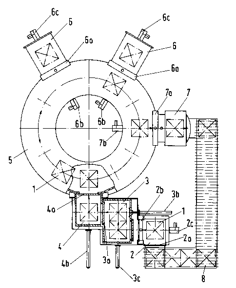
The devlce shown ln Flg. 1 for heat treatlng metal
workpleces ln charges 1 conslsts, ln dlrection of conveyance
of the charges 1, of an input channel 2, a heating chamber 3,
a compensating chamber 4, a rotary cycle furnace 5 as
diffusion furnace, two carburizing furnace chambers 6 as well
as an output channel 7.
The lnput channel 2 is fed wlth the workplece
charges to be treated vla a conveyance devlce 8 from a charge
storage place (not shown). After the lnput channel 2 has been
loaded, doors 2a and 2b of the lnput channel 2 are closed and
the lnput channel 2 ls evacuated vla a pump (not shown), slnce
the subsequent treatment of the charges 1 in chambers 3 and 2
as well as in the rotary cycle furnace 5 takes place in a
vacuum. The door 2b is then opened, charge 1 is conveyed via
25476-186
~ ~1 730~8
a pushing device 2c lnto the heating chamber 3 and door 2b is
closed again.
In the heating chamber 3 shown with two charging
locatlons, the charge 1 ls heated to the treatment
temperature, l.e. up to the temperature which also exists in
the rotary cycle furnace 5, by means of heaters (not shown).
The compensating chamber 4 adjolns the heatlng
chamber 3, whereby a door 3a is situated between the heating
chamber 3 and the compensating chamber 4 and the charge 1 is
conveyed within the heating chamber 3 via a pushing device 3c
and from the heating chamber 3 into the compensatlng chamber 4
via a pushing device 3b. As soon as a charge 1 has gone from
the heating chamber 3 into the compensating chamber 4, a new
charge 1 is brought into the heating chamber 3 via the input
channel 2.
Slnce the charges 1 are heated only from the outside
by radlation in the heating chamber 3 by means of heaters,
especially solld workpleces still do not have a uniform
temperature dlstribution once the surface has reached the
treatment temperature and the charge 1 is removed from the
heating chamber 3 in order not to load the workplece wlth too
hlgh a temperature. The temperature in the workplece can be
compensated ln the compensatlng chamber 4 whlch ls also
equlpped with neaters (not shown~. To accompllsh this, the
temperature ln the compensatlng chamber 4 ls set such that lt
is always maintained at a constant temperature, namely the
desired treatment temperature. Conventional treatment
temperatures lie between 800C and 1000C.
25476-186
21 73058
After the treatment temperature has been attained,
charge 1 ls, after a door 4a has been opened, pushed into the
rotary cycle furnace 5 by means of a pushing device 4b and
door 4a is then closed again. By means of the annular rotary
plate of the rotary cycle furnace 5, charge 1 is conveyed
directly to one of the carburizlng furnace chambers 6.
Chambers 6 are evacuated by means of a pump (not shown) prior
to a charge 1 being pushed in. A furnace chamber door 6a is
then opened and the charge 1 is pushed into the carburizing
furnace chamber 6 by means of a pushlng device 6b whlch is
arranged inside the rotary cycle furnace and the furnace
chamber door 6a is then closed agaln. The actual carburlzlng
process is carried out in the carburizing furnace chamber
which is either ln the form of a plasma furnace or a vacuum
furnace. After the designated duration of carburization has
been completed, the carburizing furnace is shut off again and,
if applicable, the process gas is removed from the carburizing
furnace chamber 6. After renewed evacuation of the
carburizing furnace chamber 6, the furnace chamber door 6a is
agaln opened and charge 1 ls again pushed back into the rotary
cycle furnace 5 by means of a pushing device 6c arranged
opposite pushing device 6b.
The diffusion phase, during which the marginal
carbon content decreases again, then takes place in the rotary
cycle furnace 5 after the carburlzing process in a vacuum at a
constant temperature. Depending on the deslred casehardening
depth, the described carburizing process and dlffuslon phase
are repeated several tlmes. Due to the constructlon of the
25476-186
2 1 73058
device wlth the rotary cycle furnace 5 for the diffusion phase
and the carburlzing furnace chambers 6 on the outslde for the
actual carburizing process, optimum use of the device is
ensured since, while a charge 1 already treated in the
carburizing furnace chamber 6 remains in the rotary cycle
furnace 5 for the diffuslon phase, another charge 1 with
perhaps other carburizing conditions can be brought into the
carburizlng furnace chamber 6. Depending on how many
carburizing furnace chambers 6 are arranged about the
periphery of the rotary cycle furnace 5, the flexibility of
this device can be increased and the treatment duration
shortened.
As soon as the last diffusion process has come to an
end in the rotary cycle furnace 5, the charge 1 ls conveyed to
ln front of a door 7a of the output channel 7. The output
channel 7 ls then evacuated, door 7a opened and charge 1
conveyed lnto the output channel 7 by means of a pushing
device 7b. After door 7a has been closed, charge 1 can be
quenched with gas or in a llquld bath ln the output channel 7
which is in the form of a cooling chamber.
The second embodlment of the devlce shown ln Flg. 2
ls made identical to the device of Fig. 1 except for the area
of the output channel 7. In this alternate embodiment, a
casehardenlng furnace 9 ls lnserted in between the rotary
cycle furnace 5 and the output channel 7 made ln the form of a
cooling chamber. A casehardening furnace 9 of this type is
necessary when the carburlzing temperature in the carburizing
furnace chamber 6 is clearly above the settlng temperature of
25476-186
~ 2173058
charge 1 and charge 1 must be cooled to the setting
temperature after the carburizlng process and prior to the
quenching. For this purpose, the charge 1 first passes
through the casehardening furnace 9 after the last diffuslon
phase in the rotary cycle furnace 5 in order to then be
quenched in the cooling chamber of the output channel 7.
With a device of this type for heat treating metal
workpieces, lt ls thus ensured that workplece charges havlng
the most varied hardening conditions can be simultaneously
treated by means of one device, without the dlfferent
hardenlng condltlons to be applled affectlng the other
charges. In addltlon to the great flexlbility of the
aforementioned installation, the use of the rotary cycle
furnace 5 as a pure dlffusion furnace wlth the attached
individual carburizing furnace chambers 6 enables optimum
utilization of the device without it being necessary for
individual processing positions having to remain empty due to
possible interactions with other charges.
25476-186