Note : Les descriptions sont présentées dans la langue officielle dans laquelle elles ont été soumises.
WO 95122952 PCTISE95/00185
1
AN ABSORBENT 80DY AND APPARATUS FOR ITS MANUFACTURE
The present invention relates to an absorbent body for an
absorbent article, such as a diaper, an incontinence guard
or a sanitary napkin, comprising a sheet or layer of
absorbent material and a layer of particles of so-called
superabsorbent material placed on the sheet of absorbent
material. The invention also relates to an arrangement of
apparatus for producing such an absorbent body.
The absorption capacity of present-day absorbent bodies in
absorbent articles of the aforementioned kind is generally
sufficient to be able to absorb all liquid discharged by
the wearer over a normal period of use. Leakage problems
associated with articles of this kind are more often than
not contingent on the ability of the absorbent body to
utilize its intrinsic absorption capacity to a sufficiently
great extent. Decisive factors in this regard are the
ability of the article to disperse and to receive liquid,
i.e. on the effectiveness of its liquid transport proper-
ties. By liquid-receiving properties is meant in the
present document the ability of the absorbent body to take-
up a given quantity of discharged liquid quickly, i.e. its
ability to transport liquid from the surface of the body
into the interior thereof. The higher the liquid-receiving
capacity, the quicker the discharged liquid is transported
into the absorbent body.
At present, it is conventional to provide the absorbent
bodies of such absorbent articles with so-called superab-
sorbent material, with the intention of increasing the
total absorption capacity of such bodies. By superabsorbent
material is meant material which is able to absorb liquid
in quantities that correspond to many times the weight of
the material. Such material is often used in the form of
powder, grains, granules, flakes, short fibres or similar
particle forms. In the case of materials of this kind, the
WO 95/22952 PCT/SE95100185
2
liquid absorbed forms a gel. The materials also have low
liquid-dispersing ability. Consequently, iW order to
utilize the high absorption capacity of superabsorbent
materials, it is necessary to arrange the materials so that
discharged liquid can be transported to all parts of the
superabsorbent material.
This can be achieved by mixing particles of superabsorbent
material in a layer of heavily compressed cellulose fluff
pulp, wherewith the capillary forces in the fluff pulp
layer spread the liquid throughout the layer and therewith
to the superabsorbent particles mixed therein.
It is also known to use separate layers of superabsorbent
material which coact with spreading or dispersion layers
disposed on one side or on both sides of the layer of
superabsorbent material. One problem that arises when using
separate layers of superabsorbent material is so-called gel
blocking, i.e. the gel that is formed when the superabsor-
2o bents absorb liquid prevents liquid from flowing through
the layer.
US-A 4,994,053 teaches an absorbent article in which a
sheet or layer which includes a pattern of discrete regions
containing superabsorbent particles drains an overlying
cellulose fluff layer, while US-A 5,118,376 teaches an
absorbent article in which superabsorbent particles are
contained in a pattern of hollows or pits in a fibre mat,
this pattern being produced by mechanical compression of
the fibre mat in said pitted regions with the aid of an
embossing cylinder or roller.
Absorbent bodies in which particles of superabsorbent
material are mixed into a layer of cellulose fluff pulp
normally have better liquid-receiving properties than
absorbent bodies in which fluff pulp and particles are
applied in mutually separate layers, particularly after
WO 95122952 2 PCT/SE95/00185
3
several liquid discharges. On the other hand, layered
absorbent bodies normally have better rewetting properties,
i.e. which when the article is subjected to load are better
able to retain the liquid absorbed by the absorbent body
than absorbent bodies in which the particles are mixed in
the fluff pulp.
In the case of the absorbent articles before mentioned, the
total liquid discharge is periodic, by which is meant that
a given quantity of liquid is discharged almost instantan-
eously, whereafter a relatively long time will follow
before the next discharge. In the case of diapers and
incontinence guards, a large amount of liquid may be
discharged on each occasion, which places high demands on
the ability of the diaper to quickly transport the dis-
charged liquid from the surface of the diaper and into the
absorbent body, i.e. the body must possess good liquid-
receiving properties in order to minimize the risk of
leakage. Since liquid is discharged several times during
the time in which an absorbent article of this kind is
intended to be worn, it is desirable that the absorbent
article will have good liquid-receiving properties on all
those liquid discharges that occur during the intended use
period of the article. Naturally, the liquid transport
properties of the article are at their best before the
first liquid discharge and are successively impaired with
subsequent discharges, although it is important that this
impairment is kept as low as possible.
An object of the present invention is to improve the
liquid-receiving properties of a layered absorbent body
while retaining its good rewetting properties.
In accordance with the invention, this object is achieved
with an absorbent body of the kind defined in the introduc-
tion which is characterized in that the layer of particle
material includes a pattern of through-penetrating
CA 02184094 2005-10-17
20615-1087
4
openings. Such an arrangement greatly improves the liquid-
receiving properties of the absorbent body in comparison
with a corresponding absorbent body comprising a fully
covering layer of particle material, while essentially
retaining the good rewetting properties of the body at the
same time.
According to one aspect of the present invention,
there is provided an absorbent body for an absorbent
article, in the form of a diaper, an incontinence guard or a
sanitary napkin, comprising at least two layers of absorbent
material and a layer of superabsorbent particles laid on
each of the layers of absorbent material, wherein the layers
of superabsorbent particles include a pattern of through-
penetrating openings and at least one of the layers of
superabsorbent material is disposed between the layers of
absorbent material.
According to another aspect of the present
invention, there is provided an arrangement for
manufacturing absorbent bodies for absorbent articles in the
form of diapers, incontinence guards or sanitary napkins,
wherein the arrangement includes first particle applicator
means for delivering particles in a given pattern onto a
moving web of material, means for passing a first fibre body
past particle applicator means, means for placing a second
fibre body on top of the first fibre body after having
applied a layer of particles to said body, a second particle
applicator means for applying to the second fibre body a
layer of particles in a specific pattern, said pattern being
displaced in relation to the particle pattern applied to the
first fibre body, and means for compressing the thus
obtained composite absorbent body.
CA 02184094 2005-10-17
20615-1087
4a
According to one preferred embodiment of the
invention, the absorbent material is comprised of a fibre
structure and the particles in the particle layer are
enclosed either completely or partially in the fibre
structure. The absorbent body also includes several layers
of absorbent material on which layers of particles are
placed, these layers including patterns of through-
penetrating openings. The openings in the different
particle layers are preferably offset horizontally in
relation to one another and overlap each other. It has been
surprisingly found that when the absorbent body is
constructed in this way, the liquid-receiving properties are
improved to such an extent as to correspond to the
properties of absorbent bodies in which the particles are
mixed in absorbent material, such as fluff pulp, without
appreciably impairing the rewetting properties.
The layers of absorbent material are preferably
comprised of compressed cellulose fluff pulp and the
penetrating openings in the layer of particle material are
filled with a cellulose fluff pulp that has been compressed
to a lesser extent than the cellulose fluff pulp that is
located externally of the openings in parts of the layer of
cellulose fluff pulp lying beneath the layer of particle
material. An~advantage is afforded when the aforesaid layers
are comprised of a fibre material which has a high liquid-
dispersing ability, for instance chemithermomechanical fluff
pulp, chemically stiffened cellulose fibres, synthetic
wadding, etc., preferably arranged on top of the uppermost
particle layer, i.e. outermost on that side of
vJ0 95122952 PCT/SE95/00185
2~~~U9~
the absorbent body which when an absorbent article contain-
ing the absorbent body is worn lies nearest to the wearer's
body, and particles of so-called superabsorbent material
are admixed in the fibre material in the upper layer or
5 sheet. According to one advantageous variant, the pattern
of openings in each particle layer is comprised of discrete
slots which extend in the longitudinal direction of the
absorbent body along the whole of its length.
The invention also relates to an arrangement of apparatus
for manufacturing absorbent bodies for such absorbent
articles as diapers, incontinence guards or sanitary
napkins, said apparatus being characterized by means for
applying particles in a specific pattern on a moving web of
material, means for moving a first fibre body past the
particle applying means, means for laying a second fibre
body on top of the first fibre body subsequent to having
applied a layer of particles on said first fibre body,
means for applying on the second fibre body a layer of
2o particles in a specific pattern which is displaced in
relation to the particle pattern formed on the first fibre
body, and means for compressing the thus composed absorbent
body. Respective means for applying particles on the first
and the second fibre bodies will each preferably include a
particle dispenser, a belt which runs above the fibre body
concerned and which includes a pattern of holes correspond-
ing to the applied particle pattern and which is spaced
from the fibre body at least to an extent which will enable
the particles laid on the fibre body to be accommodated
between the belt and said body, wherein the particle
. dispenser is intended to dispense particles continuously in
a uniform and broad stream whose width is equal to or
, slightly greater than the width of the hole pattern on the
belt, and further comprises means for carrying away
particles caught by the belt.
WO 95122952 PC1'ISE95/00185
21&094 , rp
6
The invention will now be described in more detail with
reference to the accompanying drawings, in which
Fig. 1 is a perspective, partly cut-away view of one
embodiment of an inventive absorbent body;
Fig. la is a cross-sectional view of an enlarged section of
the absorbent body shown in Figure 1;
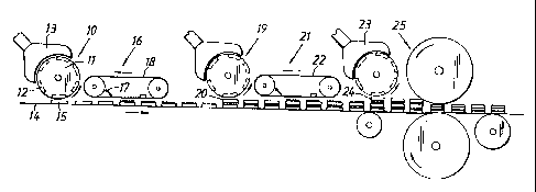
Fig. 2 is a schematic illustration of an arrangement for
manufacturing the absorbent body shown in Figure 1;
Fig. 3 illustrates a device for delivering particles to an
underlying material-web included in the arrangement shown
in Figure 2;
Fig. 4 illustrates schematically cross-sectional views of
four different test bodies;
Fig. 5 is a bar chart illustrating the liquid-receiving
time for the test bodies in Figure 4 on four successive
liquid discharge occasions and rewetting after the third
liquid discharge occasion;
Fig. 6 illustrates schematically cross-sectional views of
five further test bodies; and
Fig. 7 is a bar chart illustrating the liquid-receiving
time for the test bodies in Figure 6 on four successive
liquid discharge occasions and rewetting after the third
liquid discharge occasion.
The absorbent body 1 illustrated in Figure 1 includes two
layers 2, 3 of a fibre structure having good liquid-
dispersing or spreading properties, for-instance two layers
of chemical cellulose fluff pulp, on which layers 4, 5 of
particles of so-called superabsorbent material are applied.
W0 95122952 PC7YSE95/00185
~~84~9~
The absorbent body 1 also includes a layer or sheet 6 of a
fibre structure having a high instantaneous liquid-receiv-
ing ability, for instance a layer of chemithermomechanical
cellulose fluff pulp, chemically stiffened cellulose
fibres, synthetic wadding or the like, in which particles
7 of superabsorbent material are mixed.
The layers 4, 5 of superabsorbent particles include
respective openings 8 and 9 in the form of slots which
io extend in the longitudinal direction of the absorbent body
l, along the whole of its length. The openings 8, 9 in
respective layers 4, 5 are displaced horizontally in
relation to one another. The term vertical direction, or
vertically, as used in the present document infers a
direction which is at right angles to that side of the
absorbent body which when using an absorbent article which
includes an inventive absorbent body lies proximal to the
wearer's body.
2o Figure 2 illustrates schematically an arrangement for
continuous manufacture of absorbent bodies 1. The arrange-
ment includes a first conventional mat-forming wheel 10
which includes a rotary forming cylinder 11 provided with
moulds 12 which are filled successively with air-trans-
ported cellulose fibres with the aid of an applied sub-
pressure as the cylinder passes a header or hood 13 into
which a fluff-pulp air-transport conduit dischargers. After
the moulds 12 have passed the hood 13, the bodies 15 formed
in the moulds are deposited onto an underlying moving
conveyor belt 14 with the aid of an applied overpressure.
The deposited bodies 15 are then conveyed by the conveyor
belt 14 beneath an applicator device 16 which deposits
particles onto the bodies 15 in a specific pattern. The
device 16 is illustrated in perspective in Figure 3 and, in
principle, is constructed in the same manner as the
particle applicator illustrated and described in
R'O 95122952 ~ PCT/SE95I00185
8
SE-B 468,305. The device thus includes a particle dispenser
17 which dispenses particles in a uniform and broad stream
onto a belt 18 provided with a pattern of holes. As will be
seen from Figure 3, in the illustrated case the hole
pattern on the belt 18 is comprised of a sequence of rows
of slot-like openings formed in the belt and through which
the particles dispensed by the particle dispenser or
applicator fall down onto the passing bodies 15. As will be
understood, the speeds at which the belt 18 and the
conveyor belt 14 move are synchronized with one another so
that spaces between the rows of slots on the belt 18 will
coincide with spaces between the bodies 15 and so that the
particles will be deposited along the full length of the
bodies. The reader is referred to the aforesaid document
for a more detailed explanation of the construction of the
device 16.
After having passed the device 16, the shaped or moulded
bodies 15 carrying a pattern of particles pass beneath
another mat-forming wheel 19 at which a second moulded body
20 is placed on top of the layer of particles carried by
the body 15, whereafter the thus formed three-tier body
passes beneath a second particle applicator 21. The
particle applicator 21 is similar to the particle applica-
for 16 with the exception that the slots in the belt 22 of
the applicator 21 are displaced transversely to the
direction of movement of the conveyor belt 14 in relation
to the slots in the belt 18 of the applicator 16. The
particle patterns on the bodies 15 and 20 will therefore be
displaced transversely in relation to one another.
The composite body comprised of the moulded bodies 15, 20
and the particle layers, carried thereby then passes beneath
a third mat-forming wheel 23 where a third moulded body 24
is placed on top of each of the stack of bodies 15, 20 and
the particle layers carried thereby. The composite body
comprised of the aforesaid three moulded bodies and the two
W0 95122952 PCT/SE95/00185
9
particle layers then passes through a pair of compression
rollers 25. As the composite body is compressed, the
particle layers are pushed into respective underlying
bodies 15, 2o and the resultant slot-like openings thereby
formed in the particle layers are filled with fluff pulp
which has been compressed to a lesser degree than the fluff
pulp in the moulded bodies by said compression. This
phenomenon is illustrated schematically in Figure ia, which
illustrates a section of the absorbent body shown in Figure
1 containing the particle layer 4, the layers of fluff pulp
2, 3 and a slot-like opening 8.
With the intention of establishing the effects of the
invention, there was carried out a first comparison test in
which two mutually different test bodies constructed in
accordance with the invention were compared with two
different test bodies of a known kind with regard to the
liquid-receiving and rewetting properties of the test
bodies.
The four test bodies A-D are shown in Figure 4, from which
it will be seen that each body includes a top layer 26
comprised of chemithermomechanical cellulose fluff pulp
with which particles of a superabsorbent material have been
admixed. The superabsorbent material constitutes 10 percent
by weight of the layer 26. Each of the test bodies A-D also
includes a bottom layer 27 of chemical cellulose fluff
pulp. The test body A has a layer 28 of superabsorbent
particles sandwiched between the top and bottom layers 26
and 27. The test body B differs from the test body A by
virtue of the fact that it comprises two fluff layers 27
and a layer 29 of superabsorbent particles between said
layers. The test bodies C and D are constructed in the same
manner as-the test body B, except that the respective
layers of superabsorbent particles 30, 31 and 32, 33
include a pattern of through-penetrating slots 34 and 35,
these slots extending along the full length of respective
W0 95122952 _ _ PCTlSE95100185
2~~~094
bodies and being shown in the sectional views of Figure 4.
In test body C, the slots 34 in the different particle
layers 30, 31 are displaced in relation to one another so
as to be mutually separated horizontally, whereas the slots
5 35 in the particle layers 32, 33 of the test body D overlap
one another horizontally. The open area in the particle
layers 30, 31 of test body C is 50%, whereas the open area
in the particle layers 32, 33 in test body D is 30%.
10 The test bodies were all of the same size, 100 x 280 mm,
and were constructed from the same materials. The body A
had a surface weight of 843 g/m2 and a density of 166
g/dm3, the body B had a surface weight of 840 g/m2 and a
density of 164.8 g/dm3, the body C had a surface weight of
836 g/m2 and a density of 169.5 g/dm3, and the body D had
a surface weight of 861 g/m2 and a density of 171.1 g/dm3.
All- test bodies contained the same amount of absorbent
material.
The test bodies were tested in the following manner:
There was first applied 60 ml of test liquid (0.9% NaCl-
solution) through a hole of 80 mm in diameter in a plate
placed on the top layer 26. The admission time was mea-
sured, i.e. the time taken before all liquid had been
absorbed by the test body. This procedure was repeated
three times at 20-minute intervals between each liquid
delivery. Rewetting was measured after the third liquid
delivery, by placing eight filter papers on top of the test
body and subjecting the papers to a load of 1.1 kg (2.8
kPa) for 15 seconds. The filter papers were weighed before
and after applying the load and their increase in weight
recorded. Liquid was then applied for a fourth time and the
rewetting tendencies of the bodies was again measured.
The results of this test are shown in Figure 5, which is a
stack chart showing the liquid-receiving properties of the
W 0 95122952 PCT/SE95/00185
11
test bodies A-D. Each liquid delivery is symbolized by a
stack and the height of each stack illustrates the admis-
sion time in seconds and can be read-off from the scale
shown to the left of the Figure. The four liquid deliveries
are represented sequentially by an empty or hollow stack,
a gray stack, a black stack and a hatched stack. The scale
shown to the right of the Figure shows the weight in grams
of the liquid that has been absorbed by the filter papers
and constitutes a measurement of the rewetting properties.
The measured increase in weight of the filter papers is
symbolized in Figure 5 by a solid square.
It will be seen from Figure 5 that-the liquid-receiving
properties of test bodies A and B were essentially the
same, whereas rewetting was less pronounced in the case of
test body B. With regard to liquid transportation, it can
be concluded from this that it is more beneficial to
provide an absorbent body with two particle layers than
with one layer, assuming, of course, that the layers 27 are
constructed from material which has good liquid-dispersion
ability.
It will also be seen from the comparison illustrated in
Figure 5 that the test bodies C and D have better liquid-
receiving properties than the bodies A and B. It will also
be seen that rewetting properties were good. Despite its
large open area in the particle layers 30, 31, the body C
had a rewetting tendency which corresponded to the rewet-
ting tendency of the body A, while the rewetting tendency
of the body D was only insignificantly greater than the
rewetting tendency of the body B.
The test body D surprisingly exhibited good liquid-receiv-
ing properties which corresponded essentially with the
liquid-receiving properties of absorbent bodies comprised
of cellulose fluff pulp with uniformly intermixed particles
of superabsorbent material. Because the test body D had a
WO 95/22952 PCT/SE95100185
12
t
much smaller open area than the test body C, it could be
expected that it would have poorer liquid-receiving
properties than the body C and not better liquid-receiving
properties, as was the actual case. It will also be seen
from the stack chart in Figure 5 that the admission time in
the case of test body D was short even on the occasion of
the fourth liquid delivery. The only difference between the
construction of the test body D and the construction of the
test body C lay in the fact that the particle strands or
ribbons in the particle layers 32, 33 applied to the body
D overlapped one another horizontally to an extent refer-
enced ~ in the Figure, whereas the particle strands in the
particle layers 30, 31 applied to the body C were mutually
spaced horizontally and it is probably this structural
difference that caused the liquid-receiving properties of
the test body D to be far better than the liquid-receiving
properties of the test body C. The test bodies C and D were
manufactured by the method described above with reference
to Figure 2 and it is apparent that the relative position-
ing of the slots in the particle layers of- these bodies
locally influenced the compression of the layers of
cellulose fluff present in the bodies such as to obtain a
varied compression profile, this variation depending on
whether, as seen vertically, the body included local parts
of both the particle layers 30, 31 and 32, 33 respectively,
an opening 34, 35 and a particle layer in addition to the
cellulose fluff layers 26, 27, instead of containing solely
two openings 35. It is therefore reasonable to assume that
the large difference between the liquid-receiving proper-
ties of the bodies C and D was the result of the difference
in the mutually relative position of the openings 34 and 35
Y
in the two particle layers 30, 31 and 32, 33 respectively,
and therewith associated differences in the compression
pattern of the cellulose fluff layers 26, 27 of the test
bodies C and D.
W O 95122952 PCT/SE95/00185
13
Four different test bodies II-V constructed in accordance
with the invention were tested in the same manner as the
test bodies C and D and compared with a test body I. The
result of this comparison test is shown in Figure 7 in the
form of a stack chart which illustrates the liquid admis-
sion time in seconds and quadrates the recorded weights in
grams of liquid absorbed in the rewetting test, in the same
way as the test results obtained with the test bodies A-D
illustrated in Figure 5. The test procedures applied were
the same as those described above for testing the test'
bodies A-D.
Each of the four inventive test bodies II-V comprised a top
layer 36 of chemithermomechanical cellulose fluff pulp in
which particles of superabsorbent material were homogen-
ously admixed. The superabsorbent material corresponded to
1o percent by weight. The surface weight of the top layers
36. were 275 g/m2. Each test body II-V also included two
layers 37 of chemical cellulose fluff pulp having a surface
2o weight of 150 g/m2 and carrying respective layers 38-45 of
superabsorbent particles.
The layers 38, 39 of the test body II comprised longitudi-
nally extending strands of superabsorbent particles having
a surface weight of 157 g/m2 and separated by open slots.
The pattern of strands and slots was similar in the two
layers 38, although the patterns in respective layers were
displaced transversely in relation to one another, so that
both particle strands and slots overlapped one another. The
open area in the particle layers 38, 39 was 30%.
The layers 40, 41 of the test body III comprised longitudi-
nally extending strands of superabsorbent particles having
a surface weight of 160 g/m2 and mutually separated by open
slots. The test body III differed from the test body II by
virtue of the fact that its strands and slots were dis-
placed transversely in relation to one another, so that the
WO 95122952 PCTISE95100185
14
particle strands overlapped one another but not the slots.
Thus, the particle strands in one layer of the sample body
III completely overlapped the slots in the other layer. The
open areas in the particle layers 40, 41 were 30 and 35%
respectively.
The layers 42, 43 of superabsorbent particles in the test
body IV comprised longitudinally particle strands having a
surface weight of 183 g/m2 and being mutually spaced by
open slots disposed, as earlier, in a uniform pattern. In
this case, the patterns are not displaced transversely in
relation to one another and the particle strands and slots
completely overlap each other. The two layers had an open
area of 40%.
The uppermost layer 44 of the test body V comprised
particle strands having a surface weight of 157 g/m2 and
being separated by open slots. The uppermost layer 44 had
an open area of 60%. The bottom particle layer 45 comprised
an unbroken layer which had a surface weight of 157 g/m2.
The test bodies II-V were compared with a test body I which
comprised a similar top layer 36 to the test bodies II-V
and a bottom layer 46. The bottom layer 46 was comprised of
a chemical cellulose fluff pulp having a surface weight of
300 g/m2 and with which there were admixed homogeneously
6.16 g of superabsorbent particle material. The bottom
layer had a total surface weight of 220 g/m2.
All of the test bodies I-V measured 100 x 280 mm and were
constructed from mutually the same material.
The test bodies I-V were tested in the manner described
above with reference to test bodies A-D and the result of
the test is shown in Figure 7, in which the mutually
sequential stacks illustrate the respective admission times
of the different test bodies for successive liquid deliver-
CA 02184094 2005-10-17
20615-1087
ies. It will be seen from this Figure that the liquid-
receiving properties of the test bodies II-IV correspond
essentially with the liquid-receiving properties of the test
body I, which was comprised of two layers of cellulose fluff
5 pulp and an admixture of superabsorbent particles. The
properties of the test bodies III and IV were found to be
better than the properties of the test body I on the fourth
liquid delivery. Rewetting tendencies were far less
pronounced in the case of test bodies IT and III than in the
10 case of test body I, whereas rewetting in the case of test
body IV corresponded essentially to the rewetting tendency
of test body I. The liquid-receiving and rewetting
properties of test body V were poorer than the properties of
test body I.
15 These tests thus show that absorbent bodies which
include particle layers in which openings are provided and
in which the openings in different layers are displaced in
relation to one another have good liquid-receiving and
rewetting properties.
The absorbent body may be enclosed between a
liquid-permeable casing layer and a liquid-impermeable
casing layer.
It will be understood that the illustrated and
described embodiment can be modified in several ways. For
instance, the pattern of openings in the particle layers may
be different to those shown. For instance, instead of
parallel slots, the slots may be curved such as sinusoidal,
circular, or in the form of holes having a circular, a
rectangular, a curved, or some other shape, etc. The
mutually adjacent slots or rows of holes may slope at
different angles to the longitudinal axis of the absorbent
body. The slots may be inclined to the longitudinal axis of
CA 02184094 2005-10-17
20615-1087
15a
the absorbent body. Furthermore, the layers of absorbent
material may be pre-compressed and the absorbent bodies may
have shapes other than rectangular. The invention also
includes absorbent body constructions which include a
particle layer that has only one single opening, although
such constructions are not preferred. Embodiments which
include more than two particle layers are also conceivable,
of course. Absorbent materials other than those recited
above may also be used, although it is preferred to produce
the bottom layer or layers from chemical cellulose fluff
pulp because of its good liquid-
W0 95/22952 PCTISE95/00185
16
dispersion properties. The devices used in the manufactur-
ing plant machinery may also be configured differently to
that described. For instance, transport means for pre-
compressed fibre bodies may be used instead of mat-forming
wheels, and the number of devices included may be adapted
to produce bodies which contain more or fewer layers than
the arrangement illustrated in Figure 2. The superabsorbent
particles may also be deposited in ways other than that
described. The invention is therefore restricted solely by
l0 the content of the following Claims.