Note : Les descriptions sont présentées dans la langue officielle dans laquelle elles ont été soumises.
21 85867
MULTI-PHASF FLUID FLOW
MFASUR~MF.I~T ~pp~R~Tus ~ND MF~TTlOV
5 TFl'~l~I('AT FTFT.n
The present invention relates to a method and an apparatus for
rh~r~-t.ori7ing the flow of a multi-phase fluid, including ~t~rmining at least one of
a volumetric flow rate and a density for the fluid.
bA('TC(~ROUND .APT
The charartl~ri7~tion or m~dbu~ nl of the flow of a multi-phase fluid
presents nul~ Ls ~1iffi.~ulti~q. A multi-phase fluid is a fluid having more than15 one phase (liquid or gas), such as a fluid having two or more liquid phases or a
combmation of a gas phase with one or more liquid phases. Attempts have been
made to overcome these ~lifficlllti~ given the recognized need in industrial
applications for the accurate ~-h~r~-tori7~tinn or Ill~dbUlt~lllt~lll of the flow of such
multi-phase fluids. For example, the oil and gas industry requires accurate
20 measurement of the production of multi-phase fluids, comprising oil, hydrocarbon
gases, water and/or other associated fluids, from underground reservoirs throughwells in order that the production from each well can be assessed, managed and
allocated in a reliable and consistent manner. In addition to the oil and gas
industry, similar needs exist in other industries such as the chemical industry.
Generally, IlledSLlll~lllt:lll of the flow of a multi-phase fluid presents
11iffi( nlti.os due to the wide variety of flow regimes which are possible, general flow
instability and the likelihood of a slip between the phases of the fluid due to
b~ ,dlioll. For example, in a production well, the multi-phase fluid is likely
30 comprised of oil, water and hydrocarbon gas. A slip may occur between the oil and
water resulting in the production of separate slugs or plugs of oil and water.
Meanwhile, the gas may take the form of small bubbles, large slugs of gas or a
~ 21 85867
discrete layer of gas above the water and oil. A slip may also occur between theliquid phase and the gas phase and is more lilcely.
The conventional approach of industry to the charal tl~ri7ati-~n of multi-phase
fluid flows is fluid sampling and :~L~IJC'Ll'dliUn. A sample of the multi-phase fluid is
diverted from the flow and allowed to separate into its component phases. Once
separated, measurements may be made of the individual phases using conventional
single-phase flow measurement techniques and devices. This ~ u~lv~liundl
approach has several drawbacks. Sampling requires the extraction of a quantity of
the fluid, on either a continuous or a periodic basis, by an intrusive sampling probe.
As well, homogenization of the flow may be required prior to sampling in order to
obtain a lelul~b~l~lc.liv-- sample of the fluid. Further, sampling and separation of the
phases may be time cr)nCllming and the required e-luilullu-l-l may be costly, bulky,
complex and require ongoing ~ ,a"~ Thus, the efficiency and Pl-nnL mi~ ~ of
~u-lv~ liul-al field fluid samplers and b~pdlcLlUl~ have not been found to be
completely satisfactory.
Alternatively, Canadian Patent No. 1,134,174 issued October 26, 1982 to
Rh~ et al is directed at a device which measures the flow of a multi-phase fluidwithout sampling and separation of the phases. I~h~ describes a flow meter
which is designed to measure the individual flow rates of the phases of the fluid by
m~Rcllring a frictional pressure drop and an accelerational pressure drop of thefluid. The frictional pressure drop is measured across a twisted tape in a conduit
carrying the flow, while the afL~l.oratiL~n:ll pressure drop is measured across a
venturi positioned in the conduit downstream of the twisted tape. However, this
device does not completely address the problems associated with the variable flow
regimes, flow instability and slip in multi-phase fluid flows.
However, specific attempts have been made to address these problems as
shown by Canadian Patent Application No. 2,103,254 filed by Far- hi et al and
published September 18, 1993, United States Patent No. 3,176,511 issued April 6, 1965
to Widmyer. United States Patent No. 4,168,624 issued S~ b~l 25, 1979 to ~i~hQn,United States Patent No. 4,441,361 issued April 10, 1984 to (~Arl~r~n et al. United
--2--
~ 21 85867
States Patent No. 4,856,344 issued August 15, 1989 to ~nl, United States Patent No.
4,974,452 issued December 4, 1990 to E~lmt et ~l and United States Patent No.
5,190,103 issued March 2, 1993 to Griston et ~T.
;Farchi describes an apparatus for m~ lcnring the flow rates of the gas and
liquid components of a fluid in a series flow path. Ea~hi states that the velocity
ratio between the gas and the liquid in the series flow path is preferably ", ,i,.l,.;.,~,l
at a known value, such as one, by using either a first and second mixer or a positive
displacement flow meter. The first and second mixers are coupled at the input and
10 output of the volumetric flow meter. However, the specific method by which the
velocity ratio is effectively m~intRin~cl at one through the volumetric flow meter is
not described. Further, no definition or description of the positive displacement
flow meter, or the method by which it maintains the velocity ratio, is provided by
E~hi
Widmyer provides for a measuring apparatus which includes a plurality of
baffle plates which form the walls of a tortuous passageway for the fluid. The fluid
passes through the passageway, where it is mixed, and s-lhs~q1l.ontly through a
partition and into a separate fluid density measuring device. The fluid then passes
20 through a second partition into a separate flow rate or volume m~snring device.
Similarly, each of ~i~hnn, ~1 ~, Hnnt et ~l and Griston all describe devices
which discuss the use of a mixer or other means, for making the fluid flow
~ub~kul~ially uniform, which mixer is located upstream of the particular measuring
devices or flow meters used in each device.
Each of these patents describe the mixing of the flow of the multi-phase fluid
prior to the taking of any measurements so that the fluid may subsequently be
measured by means suitable for a single-phase fluid. However, although these
patents attempt to address the problems of varying flow regimes, flow instability and
30 slip, these problems may not be completely overcome by the devices and techniques
disclosed by these patents.
-3--
~ 21 85867
As stated, all of the devices and techniques disclosed by these patents attempt
to achieve UlliiUlllliLy in the flow of the multi-phase fluid before mPAcnring it by
mixing the b~ dl~d phases. However, partial re-segregation or separation of the
phases will occur immP~i~tPly following cessation of the mixing of the phases, or
5 once the fluid has passed through the mixer, due to the immiscibility and
differences in the densities (buoyancy or gravity b~ dliUll effect) of the fluidphases. Thus, the fluid flow bul,seyu~l.lly measured by each of the disclosed
measuring devices is not uniform or homogeneous, but rather, it is partially or
completely b~ dl~d or separated into its cu~ uul~:l-l phases. This partial or
10 complete be~ dliùll of the phases of the fluid flow can cause in~ r~/~iPc in the
measurements being made, particularly when using ll.easul~ll-ent devices and
techniques conventionally used for single-phase fluids. Conventional single-phase
fluid flow measurement devices and techniques are feasible and provide relatively
accurate measurements only when the multi-phase fluid flow is h(7m~gPnPoll.c or
15 substantially uniform.
There is therefore a need in the industry for an improved method and an
improved apparatus for relatively accurately characterizing the flow of a multi-phase fluid. As well, there is a need for a method and a device capable of
20 characterizing the multi-phase fluid flow using conventional single-phase fluid
flow mP:lcnring devices and techniques. Further, the device is preferably relatively
compact and simple and relatively P( ont~mi~ l and easy to construct and use in the
field.
25 DL~cl OSURR~ OF Il~V~NTION
The present invention relates to a method and an apparatus for
characterizing the flow of a multi-phase fluid in a relatively accurate manner as
compared to known methods and dpLpdldlUb~b. Further, the invention relates to a
30 method and an apparatus which provide for the cimlllt~npous or concurrent
mixing and mPAcnring of the multi-phase fluid flow to characterize it. By
continuously mixing the multi-phase fluid flow during the measurement of it, thewithin invention permits conventional single-phase fluid flow m~nring devices
~ 2185867
and techniques to be used, while still obtaining relatively accurate meabw~ s
for rhAr~ ",., li.", of the multi-phase fluid flow.
In the method form of the invention, the invention is comprised of a
5 method for ~ hArA--tf~ri7ing the flow of a multi-phase fluid as the fluid flows through
a conduit from a first end of the conduit to a second end of the conduit, the method
comprising the steps of:
(a) mixing the fluid as it flows from the first end to the second end such
that the fluid is substantially homogeneous at a first point in the
conduit and such that the substantial homogeneity of the fluid is
m~int~in~rl between the first point and a second point in the conduit,
wherein the first point and the second point are located between the
first end of the conduit and the second end of the conduit; and
(c) determining at least one of a volumetric flow rate of the substantially
homog~nf~ous fluid at a first location in the conduit between the first
point and the second point and a density of the substantially
homogeneous fluid at a second location in the conduit between the
first point and the second point.
The mixing step is preferably comprised of continuously mixing the fluid as it
flows from the first end to the second end. The mixing step may be accomplished or
p~l fu~ ed by any known mixing process or device, or a combination of two or more
25 such processes or devices, able to produce the substantially homogeneous fluid at
the first point and to maintain the substantial homogeneity of the fluid between the
first and second points in the conduit. However, preferably, the mixing step is
comprised of directing the fluid through at least one in-line mixer located in the
conduit. Further, the in-line mixer is preferably ~ull.~llDed of a static mixer.
In the preferred embodiment, the in-line mixer, being a static mixer, extends
substantially between the first and second ends of the conduit. Preferably, the static
mixer is CUlll,~l;Dt~d of the conduit containing a packing material for disrupting the
21 85867
flow of the fluid through the conduit. The packing material may be ~o~ d of a
plurality of permeable ellipsoidal bodies.
Further, throughout the mixing and ~~PtPrmining steps, the first and second
5 points in the conduit may be at different elevations. Where the fluid is ~ull~plised
of a liquid continuous medium, the first point is preferably below the second point.
Where the fluid is comprised of a gas continuous medium, the first point is
preferably above the second pomt. In either case, in the preferred embodirnent, the
first and second points are aligned such that the fluid flows substantially vertically
10 from the first point to the second point in the conduit.
The volumetric flow rate ~~PtPrmining step may be achieved or performed by
any known device or process, or a combination of two or more such processes or
devices, for ~7PtPrmining volumetric flow rate as long as it is compatible with, and
15 suitable for, the specific nature and p~ b of the fluid being measured. Further,
because the mixer produces a substantially homogeneous multi-phase fluid flow,
any known process or device, or combination of two or more processes and devices,
for ~1~t~rmining the volumetric flow rate of a single phase fluid may be used as long
as it is ~ a~il,le with, and suitable for, the specific nature and properties of the
20 homogeneous fluid being measured.
Preferably, the volumetric flow rate (lPtPrmining step is comprised of the
steps of:
(a) mP~cllring a pressure drop of the fluid at the first location in the
conduit, wherein the fluid has a flow pattern at the first location which
causes the pressure drop; and
(b) using the pressure drop at the first location to determine the
volumetric flow rate of the fluid at the first location in the conduit.
The flow pattern of the fluid at the first location may be created by any known
technique, process or device. However, the flow pattern of the fluid is preferably
21 85867
.
created by the in-line mixer, preferably being a static mixer, and the measuring step
is comprised of mPAsnring the pressure drop across the static mixer at the firstlocation.
The density r~PtPrmining step may be performed using one or more of any
known type of density measuring device, which may be comprised of an on-line
density mP~sllring device or an off-line density mP:lsllring device as long as it is
compatible with, and suitable for, the specific nature and properties of the fluid
being measured. Further, because the multi-phase fluid is substantially
homogPni7P~1 by the mixer, any known device, or combination of devices, for
tPrmining the density of a single-phase fluid may be used as long as it is
compatible with, and suitable for, the specific nature and p~ lie~ of the
homogeneous fluid being measured. Preferably, the density 11PtPrmining step is
performed using an on-line density measuring device comprising a nuclear
radiation or gamma ~ P~
Finally, when the ~IPfPrmining step is comprised of ~1PtPrmining the
volumetric flow rate and the density of the substantially homogeneous fluid, themethod may be further ~ull~l;se-l of the step of combining the density with the
volumetric flow rate in order to determine a mass flow rate for the fluid.
In the apparatus form of the invention, the invention is comprised of an
apparatus for characterizing the flow of a multi-phase fluid, the apparatus
comprising:
(a) a conduit having a first end and a second end, for flowing the fluid
from the first end to the second end, and a first point and a second
point located between the first end of the conduit and the second end of
the conduit;
(b) a mixer for mixing the fluid as it flows from the first end to the second
end such that the fluid is substantially homogeneous at the first point
21 85~67
.
and such that the substantial homogeneity of the fluid is m~int~inT~d
between the first point and the second point in the conduit; and
(c) means for ,1~h~rmining at least one of a volumetric flow rate of the
substantially ll~mogf~n~ us fluid at a first location in the conduit
between the first point and the second point and a density of the
substantially homogeneous fluid at a second location between the first
point and the second point.
The mixer preferably continuously mixes the fluid as it flows from the first
end to the second end. Further, the mixer may be any known type of mixing device,
or a combination of two or more such mixing devices, able to mix the fluid in a
manner to produce the substantially homogeneous fluid at the first point and to
maintain the substantial homogeneity of the fluid between the first and second
points. However, the mixer is preferably comprised of at least one in-line mixerlocated in the conduit. Further, the in-line mixer is preferably a static mixer.
Iri the preferred embodiment, the in-line mixer, being a static mixer, extends
substantially between the first and second ends of the conduit. Preferably, the static
mixer is comprised of the conduit ~ontAining a packing material for disrupting the
flow of the fluid through the conduit. The packing material may be (.~ liDI~ of a
plurality of permeable ellipsoidal bodies.
The volumetric flow rate (1~t~rmining means may be any known type of
device, or combination of devices, for flPt~rmining volumetric flow rate as long as it
is compatible with, and suitable for, the specific nature and properties of the fluid
being measured. Further, because the multi-phase fluid is substantially
homogenized by the mixer, any known device, or combination of devices, for
d~tf~rmining the volumetric flow rate of a single-phase fluid may be used as long as
it is compatible with, and suitable for, the specific nature and properties of the
homogeneous fluid being measured. In the preferred embodiment, the volumetric
flow rate determining means is ~ lpiis~l of a m~ nring device for m~ ring a
21 858b7
.
pressure drop of the fluid at the first location in the conduit, wherein the fluid has a
flow pattern at the first location which causes the pressure drop.
The flow pattern of the fluid at the first location may be created by any known
5 technique, process or device. However, the flow pattern of the fluid is preferably
created by the in-line mixer, preferably being a static mixer, such that the m~cnring
device measures the pressure drop across the static mixer at the first location. In this
preferred case, the mP~c1-ring device may be comprised of any known me~ql~ring
device or devices capable of mP:lcllring the pressure drop, such as a dirr~ "idl10 pressure device.
As well, the density ~PtPrmining means may be comprised of one or more of
any known type of density mP~cnring device, including an on-line density
mP~qllring device or an off-line density mP:~cllring device, as long as it is compatible
15 with, and suitable for, the specific nature and properties of the fluid being measured.
Further, because the multi-phase fluid is substantially homogenized by the mixer,
any known device, or combination of devices, for dPtPrmining the density of a
single-phase fluid may be used as long as it is compatible with, and suitable for, the
specific nature and properties of the homogeneous fluid being measured. However,20 preferably, the density ~lPtPrmining means is c~,...~.ised of an on-line density
measuring device comprising a nuclear radiation or gamma densitometer.
Finally, when the on-line density measuring device is comprised of a nuclear
radiation or gamma rlPnqit~mPtPr~ the apparatus, including the conduit, may be
25 adapted to minimize interference of the apparatus with the measurement of thedensity. For instance, the conduit may comprise a sealed window at the second
location to minimize interference by the conduit. Further, the ellipsoidal bodies
contained in the conduit in the preferred embodiment may be ~ iD~d of plastic
to minimize interference by the Pllir5~ l bodies with the nuclear radiation.
g
21 85867
.
BRTF.F DF.~CRIPTION OFDT.~AWINGS
Embodiments of the invention will now be described with reference to the
A~ rlllyillg drawings, in which:
Figure 1 is a schematic ~ b~l"dlion of a gas continuous medium in the
preferred embodiment of the apparatus;
Figure 2 is a schematic repr~PntAtion of a liquid continuous medium in the
10 preferred embodiment of the apparatus;
Figure 3 is a side view of the preferred embodiment of the apparatus having a
cut-away portion; and
Figure 4 is a cross-section of the apparatus of Figure 3 taken along lines 4-4.
BE~T MODE OF CARRYTNG OUT INVENTTON
The within invention is comprised of both a method and an apparatus (20)
20 for ~hArAct~ri~ing the flow of a multi-phase fluid (22). In the preferred embodiment,
the flow of the multi-phase fluid (22) is characterized by (1f~t~rmining at least one of
a volumetric flow rate and a density of the fluid (22), and preferably both.
A multi-phase fluid (22) is a fluid having more than one phase (liquid or gas),
25 such as a fluid having two or more liquid phases or a combination of a gas phase
with one or more liquid phases. The constituent phases of the multi-phase fluid
(22) may be separated into distinct layers or inter-mixed in a manner such that there
may be separate or discrete slugs or plugs of the various liquid phases or bubbles or
slugs of the various gas phases co-mingled together. Preferably, the multi-phase30 fluid (22) either includes no solid particles or includes an amount or size of solid
particles which do not substantially inhibit the flow of the fluid (22) through the
apparatus (20).
-10-
21 85867
Further, the fluid (22) may be either a gas ~:on~ uuub medium or a liquid
continuous medium, as ~ S~ d in Figures 1 and 2 respectively. A gas
continuous medium is defined as a multi-phase fluid flow medium wherein the
continuous fluid phase is a gas into which the other phases (i.e. Iiquid droplets and
5 solid particles, if present) are dispersed. A liquid continuous medium is defined as a
multi-phase fluid flow medium wherein the continuous fluid phase is a liquid into
which the other phases (i.e. gas bubbles and solid particles, if present) are dispersed.
The dispersed or distributed phase is also termed as the ~ ntim]l~us phase. In the
preferred embodiment, the composition of the fluid (22) is either a gas . f~ntin10 or a liquid continuous medium. Further, the flow of the fluid (22) may be an
annular dispersed flow such that either a liquid film annulus or a gas film annulus
may be present depending upon whether the fluid (22) is a gas continuous medium
or a liquid continuous medium respectively.
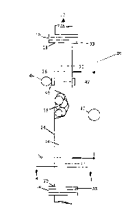
Referring to Figures 1 and 2, the apparatus (20) is comprised of: a conduit (24),
having a first end (26) and a second end (28), for flowing the fluid (22) therethrough
from the first to the second ends (26, 28), and a first point (30) and a second point (32)
located between the first and second ends (26, 28); and a mixer (34) for mixing the
fluid (22) as it flows from the first to the second ends (26, 28) such that the fluid (22)
20 is substantially homogeneous at the first point (30) and such that the substantial
homogeneity of the fluid (22) is maint:lin~l between the first and second points (30,
32). The first point (30) is located nearer the first end (26) than the second point (32),
while the second point (32) is located nearer the second end (28) than the first point
(30). Further, the longitudinal axis of the conduit (24) extending between the first
25 and second ends (26, 28) is preferably straight, without any bends, angles or curves.
The first end (26) of the conduit (24) is defined by the point at which the
mixing of the fluid (22) ( ~-mm.on- ~ Due to a mixmg entrance effect, when the
mixing of the fluid (22) I r~mm~n~ ~, the fluid (22) is not immP~ t~ly substantially
30 homogenrous. Rather, the fluid (22) must undergo a period of mixing in order to
achieve a substantially homog~n~l-us state. As a result, the first end (26) of the
conduit (24), at which the mixing commences, must be located a sufficient distance
upstream of the first point (30) to take into account the mixing entrance effect and to
21 85867
allow the mixing to act on the fluid flow and thereby produce the substantially
homogeneous fluid at the first point (30).
The second end (28) of the conduit (24) is defined by the point at which the
5 mixing of the fluid (22) is able to cease and yet still produce the s11hct:~nti~lly
homogeneous fluid between the first and second points (30, 32). Due to a mixing
exit effect, the substantial hom--g.on.oity of the fluid (22) may not be m~int~in~.1 for a
distance upstream of the point at which the mixing actually ceases. As a result, the
second end (28), at which the mixing of the fluid (22) ceases, must be located a10 sufficient distance downstream from the second point (32) to take into account the
mixing exit effect and thereby maintain the substantial homogeneity of the fluid (22)
between the first and second points (30, 32).
The conduit (24) is defined by the distance between the first and second ends
15 (26, 28). The minimum length of the conduit (24) is govemed by the need to
provide the fluid (22) with sufficient residence time within the conduit (24) topermit mixing of the fluid (22) such that it is s1lhst~nti~lly homogeneous at the first
point (30) and between the first and second points (30, 32) and to permit
char~. t~ri7Ati~-n of the substantially homogeneous fluid by the characterizing means
20 described below. The m~Yimllm length of the conduit (24) is governed primarily by
the m~Yimllm permissible pressure drop between the ends (26, 28) of the conduit
(24). The conduit (24) is preferably cylindrical in cross-section and its diameter must
be selected to permit the flow of the fluid (22) through the conduit (24) without
causmg c;gnifin~nt backup in the flow or excessive pressure drop and to provide
25 sufficient space within the conduit (24) for ~ r~nt~ining other elements of the
apparatus (20), as described below. As a result, both the diameter and the length of
the conduit (24) are dependent upon the volumetric flow rate of the fluid (22)
through the conduit (24) and upon the composition and other characteristics of the
fluid (22).
Generally, the overall design of the preferred embodiment of the apparatus
(20), including each nf~n~titl1~nt element such as the conduit (24), are dependent
upon the ~:ull-p~siliol~ and other characteristics of the fluid (22), the fluid flow rate
21 85867
.
and the desired pressure drop of the fluid (22) in the apparatus (20), as discussed
further below. Specifically, based upon these variables, the preferred embodiment,
and the parameters and sp~-ifif~tionc of its elements, are designed in order to
achieve the desired results, as described below.
The conduit (24) may be comprised of any erosion and corrosion-resistant
material capable of with~t:lnl1ing the pressure of the fluid (22) within the conduit
(24) and which will not interfere with the (~h:~r~ t-~ri7:1til~n of the fluid flow by the
apparatus (20). In the preferred embodiment, the conduit (24) is comprised of a steel
10 pipe. However, the specific material requirements of the conduit (24) will vary
depending upon the characteristics and nature of the fluid (22) flowing
therethrough.
The conduit (24) may be connected mto the flow of the fluid (22) by any
15 suitable means. However, in the preferred embodiment, a connector flange (33) is
located at each of the first and second ends (26, 28). Depending upon the specific
connector flange (33) being used, the diameter of the conduit (24) may decrease or
increase slightly at or near either or both of the first and second ends (26, 28) in order
that the conduit (24) may be more easily connected into the fluid (22) flow.
20 Preferably, the reduction or enlargement in the diameter occurs gradually in order
to decrease the effect of the changed diameter on the flow of the fluid (22).
As stated, the mixer (34) mixes the fluid (22) in the conduit (24) such that thefluid (22) is substantially homogeneous over the cross-section of the conduit (24) at
25 the first point (30) and such that the substantial homogeneity of the fluid (22) is
lllaill~ailled over the cross-section of the conduit (24) between the first point (30) and
the second point (32) in the conduit (24). The homogeneity is maintained by the
mixer (34) continuously mixing the fluid (22) as it flows from the first to the second
ends (26, 28). The fluid (22) is considered to be substantiâlly homogeneous when the
30 mixing variation coefficient (omega/x~) of the fluid is 0.05 or less, where "omega" is
the standard deviation of the ~ n(~entr~ti~n "x" (concentration distribution over the
section being considered) of one phase in the fluid (22) and "x'l" is the mean
concentration.
21 8586t
.
As well, the apparatus (20) is further comprised of means for rlPtprmining at
least one of the volumetric flow rate and the density of the substantially
homogeneous fluid. Preferably, the apparatus (20) includes means for IlP~ .llillilIg
5 both the volumetric flow rate and the density. The volumetric flow rate
,1PtPrmining means ~lPtPrmin.o the volumetric flow rate of the substantially
homogeneous fluid at a first location (36) in the conduit (24). The density
dPt~rmining means determine the density of the substantially homogeneous fluid
at a second location (42) in the conduit (24). both the first location (36) and the
second location (42) are located between the first and second points (30, 32). Thus,
the apparatus (20) provides for the simllltAnP--us or concurrent mixing and
hArA- tori7ing of the fluid (22). The volumetric flow rate and the density of the fluid
(22) are dPtPrmin~(1 at locations in the conduit (24) at which the mixer (34) has
caused and maintains the substantially homogeneity of the fluid (22).
The mixer (34) may be comprised of any known type of mixing device, or a
(r)mhinAtil-n of one or more such devices, capable of producing and l.l ,i"l,,ill;"g the
sllhstAntiAlly homogeneous fluid (22) between the first and second points (30, 32) in
the conduit (24). Therefore, the mixer (34) must be u~ palil~lc with the specific
nature and properties of the fluid (22) being mixed. Preferably, the mixer (34) is an
in-line mixer located within, or substantially within, the conduit (24) in a manner
and at a location within the conduit (24) to produce the substantially homogeneous
fluid at the first point (30) and between the first and second points (30, 32). Further,
the in-line mixer is preferably a static mixer due to the relative simplicity, energy
efficiency and cost effectiveness of static mixers as compared to other mixers.
In the preferred embodiment, the static mixer (34) extends substantially
between the first end (26) and the second end (28) of the length of conduit (24). As a
result, the mixer (34) mixes the fluid (22) continuously from the first to the second
ends (26,28). The mixer (34) thereby achieves substantial homogl~nPity of the fluid
(22) at the first point (30) and maintains 5~lhstAntiAl homogeneity of the fluid (22) as
it flows from the first to the second points (30, 32), and thus, at the first and second
locations (36, 42). Although not preferred, a gap in the mixer (34), being an area
-14-
21 85867
.
between the first and second ends (26, 28) not l-ont~ining the mixer (34), is
p~ bil,le as long as the mixing effect from the mixer (34) maintains the
substantial homogeneity of the fluid (22) in the gap. In essence, the mixer (34)duw~.sll~dll. from the gap produces an upstream mixing effect, while the mixer (34)
5 upstream from the gap produces a d~w~ dlll mixing effect. The upstream and
duwl~ a~ mixing effects act together to produce a continuous mixing action of
the fluid within the gap. Thus, the permissible size of the gap will depend upon the
extent of the mixing effects produced by the mixer (34) on either side of the gap.
Further, the static mixer (34) is preferably comprised of the conduit (24)
. nnt~ining a packing material which extends from the first end (26) to the second
end (28) of the conduit (24). The packing material allows the fluid (22) tû flowl-uugh, while creating a tortuous flow path which disrupts the flow of the
fluid (22) sufficiently to mix the fluid (22) to a substantially homogeneous state. A
mixer (34) comprised of the packing material is preferred because the packing
material, and thus the mixer (34), are relatively compact, simple in their structure,
and easy and inexpensive to use, maintain and replace, as needed, as compared toother known mixers.
Any packing material may be used which is capable of mixing the fluid (22) in
a manner to achieve substantial homogeneity at a wide range of flow rates. Further,
the packing material should be chosen so that it is compatible with the fluid (22) and
so that the mixing effect caused by it does not result in a permanent change in the
fluid flow ~h~r~ pri~ti~ or an excessive pressure drop of the fluid (22). As well, the
packing material is preferably light weight and rugged. Any suitable configuration
of the packing material may be used, including broken solids, shaped packings and
grids. Ilowever, packing materials with low porosity, low crushing strength or high
density are not preferred. In selecting the type, configuration and specific
~im~n~if)nc of the packing material to be used, some of the factors to be considered
are as follows: the length and overall (1imf~n~ions of the conduit (24); the amount
and size of any solids in the fluid (22), so that any plugging by the solids is
",i"i",;,~l1, and other fluid char~tf~rictir~; the acceptable pressure drop as the fluid
(22) passes through the packing material; the flow rate of the fluid (22) through the
21 85867
.
conduit (24); and the ability to pack the material to provide good packing
fh~ral~tf~rictir~.
In the preferred embodiment, the packing material is ~u~ i~d of a plurality
of hollow, permeable, ~llips~ l bodies (38). However, although hollow bodies (38)
are used in the preferred embodiment, the bodies (38) need not be hollow as long as
the packing material has the characteristics noted above. Further, the bodies (38)
may have a shape other than an ellipsoid, such as a rhomboid or a cylinder.
However, ellipsoidal bodies (38) are preferl~ed~as they permit close packing of the
bodies (38) within the conduit (24) and provide a relatively high void space, low
blockage tendency, low pressure drop of the fluid (22) passing ll.~ uugh, and
high active surface area for mixing the fluid (22). Due to the relatively low pressure
drop, the ~llip5nirl~l bodies (38) are particularly suited to a wide range of flow rates
and the preferred apparatus (20) may be used where excessive pressure drops are
likely to be a concern. The ellipsoidal bodies (38) may be made of any suitable
material which is compatible with the fluid (22). However, the ellipsoidal bodies
(38) are preferably made of plastic as plastic is relatively illt~p~ iVt~, light weight,
aliblc with most uses of the apparatus (20) and will not tend to interfere with
the equipment used to measure and l~h:lrartl~ri7r the fluid (22), as discussed further
below. Suitable plastics include polyethylene, polypropylene and
polytetrafluorethylene.
The preferred ~llip~o~ l bodies (38) used in the apparatus (20) are sold under
the registered trade-mark TRI-PACKS(~) by Jaeger Tri-Packs Inc. and are generally
described in United States of America Patent No. 4,203,935 granted May 20, 1980 to
Rolf Jaeger. The TRI-PACKS(~) packing is cu---p.;sed of spherical bodies shaped in a
lattice-work jacket or network of ribs and struts. Although specifically designed as a
filter medium, it has been foumd that the TRI-PACKS(~) packing may be used in the
within invention to effectively mix the fluid (22). The size of the preferred TRI-
PACKS~}' packing will depend upon the diameter of the conduit (24). However,
generally, TRI-PACKS~V packing having a diameter of about 25 mm, being the
smallest size commercially available, is preferred as this size appears to be most
21 85867
.
versatile. TRI-PACKS~ packing having a diameter of 25 mm can typically be used
in varying sizes of conduit (24) having larger or smaller ~ m~f~r~.
Further, in the preferred embodiment, a screen (39) is located across the
5 conduit (24) adjacent the connector flange (33) at each of the first and second ends
(26, 28) of the conduit (24). The screens (39) are sized to permit the flow of the fluid
(22) into and out of the conduit (24) relatively unimpeded while retaining the
ellipsoidal bodies (38) within the conduit (24). Further, the screen (39) at the first
end (26) may also be selected to filter solid particles of a desired size from the fluid
10 (22) and prevent their entry into the conduit (24).
Although the preferred mixer (34) is described above, as stated, the mixer (34)
may be .u,l.~l;Ded of any known type of mixmg device capable of p~fulllLillg thefunction of the preferred embodiment described herein. Thus, the mixer (34) may
15 be ~u~ i~d of a rotary mixer, a recirculating jet mixer, other types of static mixer
or a variable geometry static mixer. Other types of static mixer include flow
diverters, perforated pipes, sieve plates, corrugated plates, helical vanes and the like,
which compel the fluid (22) to change direction abruptly and thereby promote
turbulence and mixing of the fluid (22). Further, a variable geometry static mixer
20 may be used, if needed, to regulate the di~,ul.Liu,l of the fluid (22) as the volumetric
flow rate of the fluid (22) through the conduit (24) changes.
As well, the mixer (34) may be comprised of a combination of two or more
known types of mixing devices which act together to produce the substantially
25 homogeneous fluid between the first and second points (30, 32) in a manner similar
to the mixing effect achieved when a gap exists in the mixer (34), as described above.
For instance, a first mixer (not shown) may be located adjacent the first point (30)
and a second mixer (not shown) may be located adjacent the second point (32). A
first downstream mixing effect of the first mixer and a second upstream mixing
30 effect of the second mixer together produce the substantially homogeneous fluid
between the first and second points (30, 32). The first and second mixing effects
combine to result in a continuous mixing of the fluid (22) between the first andsecond points (30, 32). Thus, the acceptable distance between the first and second
-17-
21 85867
.
mixers will be dependent upon the extent of the first and second mixing effects.Preferably, the first and second mixers abut to ensure that the fluid (22) is mixed
continuously as it flows from the first point (30) to the second point (32).
In the preferred embodiment, it has been found that the placement of the
conduit (24) in other than a substantially hori70nt:l1 oriPnt~tion reduces the
avitatiulldl segregation of the fluid (22) by the mixer (34). Thus, the first point (30)
and the second point (32) in the conduit (24) are preferably located at different
elevations from the hnri~r~ntAI such that the longitn~lin~3l axis of the conduit (24),
extending between the first and second points (30, 32), is not substantially
h(~ri7~nt~1 Most preferably, the lnngihl~in~l axis of the conduit (24) is substantially
vertical. In other words, the first and second points (30, 32) are aligned such that the
fluid (22) flows substantially vertically from the first point (30) to the second point
(32). In the preferred embodiment, the first point (30) may be either above or below
the second point (32) in the conduit (24) (1PpPn~ling upon the composition of the
fluid (22). If the fluid (22) is a liquid continuous medium, the first point (30) is
preferably below the second pomt (32) in the conduit (24) so that the fluid (22) flows
upwards in the conduit (24), and thus follows the tendency of the gas phase or
phases to rise. If the fluid (22) is a gas continuous medium, the first point (30) is
preferably above the second point (32) in the conduit (24) so that the fluid (22) flows
downwards in the conduit (24), and thus follows the tendency of the liquid phase or
phases to fall.
The volumetric flow rate ~PtPrmining means of the apparatus (20) may be
comprised of any known device, or combination of two or more devices, for
~ptPrmining volumetric flow rate which is compatible with, and suitable for, thespecific nature and properties of the fluid (22) being measured. Further, as the fluid
(22) is substantially homogeneous at the first location (36) where the volumetric
flow rate is llPtPrminPfl, the volumetric flow rate 11PtPrmining means is preferably
comprised of any known device, or romhini~tion of two or more devices, able to
relatively accurately measure the volumetric flow rate of a single phase fluid.
However, as a single phase fluid may be comprised of either a liquid phase or a gas
21 85867
.
phase, the specific device used must again be compatible with, and suitable for, the
specific nature and ~lU~lLi~ of the hr~mogpnpclus fluid being measured.
In the preferred embodiment, the fluid (22) has a flow pattern at the first
5 location (36) in the conduit (24) which causes a pressure drop of the fluid (22) at the
first location (36). As a result, the preferred volumetric flow rate rlP~rminingmeans is comprised of a mPACllring device (40) for mPAcnring the pressure drop of
the fluid (22) at the first location (36). Thus, the measuring device (40) must be
capable of mPAcllring the range of the mAgnihl~P of the pressure drop anticipated at
10 the first location (36).
The flow pattern causing the pressure drop is preferably created by the mixer
(34). Thus, in the preferred embodiment, the mPAcllring device (40) measures thepressure drop across the mixer (34) at the first location (36). The first location (36) is
15 not a single point or place in the conduit (24), but rather, a physical distance or
amount of space between two points or places. In the preferred embodiment, the
mixer (34) substantially extends from the first to the second ends (26, 28) of the
conduit (24) and therefore extends between the points or places in the conduit (24)
defining the first location (36). Thus, the measuring device (40) measures the
20 pressure drop across the portion of the mixer (34) located at the first location (36) or
located between the points or places in the conduit (24) defining the first location
(36). In the preferred embodiment, the mAgnitll~P of the ~ .1 pressure drop
at the first location (36) will vary depending upon the nature and ~UII~U:jiLiUlL of the
multi-phase fluid (22) and the specific mixer (34) being used.
In the preferred embodiment, the mPAcnring device (40) is ~:u--lp.iswl of a
conventional differential pressure device located at the first location (36) which
measures directly the difference in pressure between the two points defining thefirst location (36). AlLt~ aLiv~ly, a first pressure gauge or tap (not shown) and a
30 second pressure gauge or tap (not shown) at the first location (36) could be used in
order to make two separate pressure measurements at the first location (36) which
can then be compared to each other to determine the pressure drop. This
embodiment, however, tends to provide a less accurate Ill~:d~ult~ L of pressure
-19-
2 1 85867
.
drop than does a differential device. However, as indicated, the mP~q1lring device
(40) may be .~ pl;Ded of any other suitable known device for measuring the
pressure drop of the fluid flow at the first location (36). The pressure drop is then
used to determine the volumetric flow rate of the fluid (22) at the first location (36).
Although the flow pattern of the fluid (22) which causes the pressure drop is
preferably created by the mixer (34), it may alternately be created by the volumetric
flow rate mP~enring device (40), which is located at the first location (36). Thus, the
volumetric flow rate mP:lcllring device (40) measures the pressure drop across the
10 measuring device (40) at the first location (36). In this case, the measuring device
(40) may be comprised of an orifice, a venturi, a nozzle or a similar mP~c1lringdevice (not shown) positioned at a gap in the mixer (34) at the first location (36). As
indicated above, where a gap exists in the mixer (34), the gap must be small enough
to permit the upstream and dowllDll~dlll mixing effects to act together to result in a
15 I ontimlollc mixing of the fluid (22) through the gap and thus, through the
mP~cnring device (40). These types of measuring devices typically result in large
pressure drops and therefore their use may not be desirable in some ~ ullls~ ces~lPpPn~ling upon the other operating p:lr~mPtPrc and (~on~litif~nc of the apparatus (20)
and the fluid (22).
The density ~l~tPrmining means may be comprised of any known density
mP~snring device (44), or combination of devices, compatible with, and suitable for,
the specific nature and properties of the fluid (22) being measured. Further, as the
density ~1.otPrmining means is mPlcnring the density of a homogeneous fluid in the
25 preferred embodiment, the density fiPtPrmining means is preferably comprised of
any known device, or combination of devices, able to relatively accurately measure
the density of a single phase fluid. However, as a single phase fluid may be
~vll~l;Ded of either a liquid phase or a gas phase, the specific device used must again
be compatible with, and suitable for, the specific nature and properties of the
30 homogeneous fluid being measured.
As described previously, the density mP~cnring device (44) ~PtPrminPC the
density of the fluid (22) at the second location (42) in the conduit (24). The second
-20-
~ 21 85867
location (42) is located between the first and second points (30, 32) within the portion
of the conduit (24) ~ontAining the mixer (34). Therefore, the fluid (22) at the second
location (42) is substantially homogeneous. In contrast to the first location (36)
which is a physical distance between two points or places, the second location (42)
5 may be either a single point or place in the conduit (24) or a physical distance or
amount of space between two points or spaces in the conduit (24). Further, the
second location (42) may be contiguous or coincident with the first location (36).
Although all of the riim~ncionR of the apparatus (20) should be designed in
10 order to achieve the desired results as set out herein, it has been found that as a
general rule of thumb, or starting point for the design of the apparatus (20), the
following mathematical ~ " "~ ,5 to the diameter of the conduit (24) may apply.
The minimum length of the conduit (24) between the first and second ends (26, 28)
may be about thirty times the diameter of the conduit (24). The distance between the
15 two points or places in the conduit (24) defining the first location (36) may be about
twenty to twenty-five times the diameter of the conduit (24). The distance between
the first end (26) of the conduit (24) and the first location (36) (i.e. the upstream point
or place defining the start of the first location (36)) may be about fifteen times the
diameter of the conduit (24). Finally, the second location (42) may be a distance of
20 about three to four times the diameter of the conduit (24) upstream of the
downstream point or place defining the end of the first location (36).
The density measuring device (44) may be comprised of an on-line or off-line
density measuring device such as a capacitance (1~ncitom~t~r, a neutron al~"~ ",25 fi~"sil..""~, and a nuclear radiation or gamma ~nsitom.ot~r. However, in the
preferred embodiment, the density measuring device (44) is ~ ised of an on-line
density measuring device in order that the measurement will be continuous. The
preferred on-line density m~Aqllring device (44) is comprised of a nuclear radiation
or gamma (1~nsitom~t~r. Further, a dual energy gamma (ll~ncitom~t~r may be used
30 in order that both the density and the composition of the fluid (22) may be
t~rmin~.
21 85867
When using a nuclear radiation or gamma ~IPn~itnmPtPr (44), the apparatus
(20), and in particular the conduit (24) and the mixer (34), may need to be adapted to
minimize any interference with the L-ledsL.-~---ent of the density by the nuclear
radiation or gamma ~ lhi~ (44). For instance, in the preferred embodiment,
5 to minimize interference by the conduit (24), which is preferably ~:u-~ d of a steel
pipe, the conduit (24) defines a window (46) at the second location (42) of a sufficient
size to allow the nuclear or gamma radiation to pass therethrough without
nt~fting the conduit (24). The window (46) is sealed to prevent the escape of any
fluid (22) out of the conduit (24) through the window (46). The window (46) is
10 sealed with a material, such as a beryllium laminated plastic, which will notsubstantially interfere with the nuclear or gamma radiation. Generally speaking,the presence of metal in the conduit (24) may interfere with the nuclear radiation or
gamma ~iPnRitomPtpr (44). Although a sealed window (46) is preferred, alternately,
other adaptations may be made which similarly minimize the interference of the
15 conduit (24) with the measurement of the density by the L~ l (44), such as
construction of the entire conduit (24) out of a non-intPrfPring material.
Similarly, the ellipsoidal bodies (38), or other packing material, contained in
the conduit (24) are preferably comprised of material which will minimize the
20 interference of the ellipsoidal bodies (38) with the measurement of the density.
Thus, the ellipsoidal bodies (38) are ~v~ ised of a non-metallic material with
negative absv.~livily to nuclear and gamma type radiation. In the preferred
embodiment, the ellipsoidal bodies (38) are comprised of plastic.
Finally, the apparatus (20) may be further comprised of, or used in
conjunction with, a fluid composition analyzer (not shown) for analyzing the
~vlllpobiliun of the fluid (22). Any known on-line or off-line fluid compositionanalyzer may be used to determine the ~:vlll~osilivr of the fluid (22) as long as it is
compatible with, and suitable for, the specific nature and properties of the fluid (22)
being analyzed. However, an on-line fluid composition analyzer is preferred.
Alternatively, a separate fluid composition analyzer will not be required in theevent that a dual energy gamma ~PncitL~mPtPr (44) is used, which can rlPtPrminP
both the density and the composition of the fluid (22).
-22-
21 858b7
The method of the within invention chArArtf~ri7.o~ the flow of the multi-
phase fluid (22) as the fluid (22) flows through the conduit (24). Preferably, the
method is ~l7nrlnch~ or performed using the apparatus (20) described above. As
indicated previously, the spe~-ificAtifm~ and paldllLeL~lD of the preferred embodiment
5 of the apparatus (20) are designed to accommodate, and be cùlllpaLilJle with, the flow
rate of the fluid (22), the composition and other ~~hArAft~ristirc of the fluid (22) and
the desired pressure drop in the apparatus (20). Further, in order to maintain the
accuracy of the apparatus (20), the apparatus (20) should be calibrated before use.
In the method, the fluid (22) is characterized as it flows from the first end (26)
to the second end (28) of the conduit (24). Ihus, the apparatus (20), and specifically
the conduit (24), must be connected into a flow of the multi-phase fluid (22), such as
a pipeline, so that the fluid (22) flows through the conduit (24) from its first end (26)
to its second end (28). The method for ~ hRrAct~ri7ing the fluid (22) flow is ~u~l~p~is~d
15 of the steps of mixing the fluid (22) as it flows from the first end (26) to the second
end (28) such that the fluid (22) is substantially homogeneous at the first point (30)
in the conduit (24) and such that the substantial homogeneity of the fluid (22) is
mAintAin~rl between the first point (30) and the second point (32) in the conduit (24).
Further, the method is comprised of flf~t~rmining at least one of the volumetric flow
20 rate of the substantially homogenous fluid (22) at the first location (36) and the
density of the substantially homogeneous fluid (22) at the second location (42).Preferably, the ~ tf~rmining step (1et~rminf~q both the volumetric flow rate and the
density of the substantially homogeneous fluid (22).
Further, preferably, the mixing step is comprised of continuously mixing the
fluid (22) as it flows from the first to the second ends (26, 28). As the first and second
locations (36, 42) are located in the conduit (24) betv~een the first and second points
(30, 32), the mixing of the fluid (22) and the ~ hArA.~ of the fluid (22) by thefi~t~ormining step are performed cimllltAnl~ously or concurrently.
The mixing step is comprised of directing the fluid (22) through the mixer (34)
in the conduit (24), as described above, to produce the substantially hu.~,o~ uuD
fluid (22). Thus, in the preferred embodiment, the mixing step is ~UIII~1;Dt~d of
21 85867
.
disrupting the flow of the fluid (22) through the conduit (24) by directing the fluid
(22) through the packing material in the conduit (24), preferably being a plurality of
hollow, permeable ellipsoidal bodies (38).
The volumetric flow rate df~t.ormining step is preferably comprised of the
steps of m~Ac-lring the pressure drop of the fluid (22) at the first location (36), which
pressure drop is caused by the flow pattern of the fluid (22) at the first location (36),
and using the pressure drop to determine the volumetric flow rate of the fluid (22)
at the first location (36). In the preferred embodiment, the flow pattern is created by
the mixer (34). Therefore, the measuring step is comprised of measuring the
pressure drop across the mixer (34) at the first location (36). The volumetric flow
rate measuring step is ~lf.~ d by the volumetric flow rate m~Ac1lring device (40)
described above. Alternately, if the flow pattern is created by the ml~Acllring device
(40), the measurmg step is comprised of m.oAcllring the pressure drop across themeasuring device (40) at the first location (36).
Once the pressure drop is measured, the pressure drop is used to determine
the volumetric flow rate either by applying a theoretical, mAth~mAtifAI model orequation defining the r~lAti-nfihir between the pressure drop and the volumetricflow rate for the specific fluid flow or by applying empirical test data defining the
r~lAti-mship between the pressure drop and the volumetric flow rate for the specific
fluid flow. Preferably, calibration test data on the fluid flow should be obtained for
the apparatus (20) as such data tends to be more accurate due to the limitAtion.s of
the mAthf~mAtifAI model to take into account the flow phenomenon of the
particular apparatus (20) being used.
Although the volumetric flow rate determining step is preferably comprised
of the steps noted above, this step may be comprised of any known process, or
combination of processes, suitable for the specific nature and ~ Iti~ of the fluid
(22) being measured. Further, as the volumetric flow rate is being d~t~rmin~d for a
substantially homogeneous fluid, the volumetric flow rate d~t~rmining step may be
comprised of any known process, or combmation of processes, able to relatively
accurately d~t~rmin~ the volumetric flow rate of a single phase fluid as long as it is
-
21 85867
.
compatible with, and suitable for, the specific nature and properties of the
homogeneous fluid being measured. For instance, the volumetric flow rate
~7,ot~Qrmining step may be performed using a cross-correlation technique at the first
location (36). Cross-correlation techniques involve the correlation of the
fluctuations of any property in the flowing fluid (22) between two pomts.
The density ~tPrmining step is preferably performed by using the density
measuring device (44) described above. Howe,ver, this step may be comprised of any
known process, or combination of processes, for ~l~t~rmining density which is
suitable for the specific nature and properties of the fluid (22) being measured.
Further, as the density is being determined for a substantially homogeneous fluid,
the density ~tPrmining step may be comprised of any known process, or
combination of processes, able to relatively accurately determine the density of a
single phase fluid as long as it is compatible with, and suitable for, the specific
nature and properties of the homogeneous fluid (22) being measured.
In the preferred embodiment, in order to facilitate the mixing and
~t~rmining steps, the first and second points (30, 32) in the conduit (24) should be
maintained at different elevations throughout the steps. Particularly, if the fluid is
comprised of a liquid continuous medium, the first point (30) in the conduit (24)
should preferably be below the second point (32) throughout the mixing and
~ ti~rmining steps. Conversely, if the fluid (22) is a gas ~mlilluuub medium, the
first point (30) in the conduit (24) should preferably be above the second point (32)
throughout the mixing and ~ t~rmining steps. In either case, the first and second
points (30, 32) are preferably aligned such that the fluid (22) flows substantially
vertically from the first point (30) to the second point (32).
Further, the method is preferably further comprised of the step of combining
the density of the fluid (22) with the volumetric flow rate in order to ~,~tl,rmin.o the
mass flow rate for the fluid (22). Any known techniques for using the density and
the volumetric flow rate to determine the mass flow rate may be used.
-25-
21 85867
.
Finally, the method may be further comprised of the steps of ~t~ormining the
composition of the fluid (22) and combining the composition with the density of the
fluid (22) to determine the flow rate of each constituent element of the fluid (22).
Any known methods or techniques for ~l~trrmining the fluid composition may be
5 used as long as it is compatible with, and suitable for, the specific nature and
properties of the fluid (22) being analyzed. Further, any known methods or
techniques for combining the composition with the density to determine the flow
rate of the ~~f)nctitll.ont elements of the fluid (22) may be used.
-26-