Sélection de la langue

Search

Sommaire du brevet 2192204 

Énoncé de désistement de responsabilité concernant l'information provenant de tiers

Une partie des informations de ce site Web a été fournie par des sources externes. Le gouvernement du Canada n'assume aucune responsabilité concernant la précision, l'actualité ou la fiabilité des informations fournies par les sources externes. Les utilisateurs qui désirent employer cette information devraient consulter directement la source des informations. Le contenu fourni par les sources externes n'est pas assujetti aux exigences sur les langues officielles, la protection des renseignements personnels et l'accessibilité.

Disponibilité de l'Abrégé et des Revendications

L'apparition de différences dans le texte et l'image des Revendications et de l'Abrégé dépend du moment auquel le document est publié. Les textes des Revendications et de l'Abrégé sont affichés :

  • lorsque la demande peut être examinée par le public;
  • lorsque le brevet est émis (délivrance).
(12) Demande de brevet: (11) CA 2192204
(54) Titre français: RACCORD FILETE
(54) Titre anglais: THREAD COUPLING
Statut: Réputée abandonnée et au-delà du délai pour le rétablissement - en attente de la réponse à l’avis de communication rejetée
Données bibliographiques
Abrégés

Abrégé français

Raccord fileté pour sondage à percussion comprenant au moins un filetage mâle (10) disposé sur un bout mâle (11) et un filetage femelle (17) situé à l'intérieur d'un manchon. Les filets sont cylindriques et comportent une surface extérieure de butée (20) à une extrémité libre du manchon, ainsi qu'une surface de contact (14) située sur le bout mâle. De plus, ils comportent une surface intérieure de butée (21) située dans le manchon et une surface terminale (16) à l'extrémité libre du bout mâle. Un jeu (.delta.) initial existe entre la surface terminale (16) du bout mâle et la surface intérieure de butée (21) du manchon, ce jeu étant éliminé après l'usure du raccord fileté. L'agrandissement de l'angle du pas (.alpha.) des filets (19, 17) permet de limiter le serrage du raccord, sous l'effet de la butée inférieure d'épaulement, tout en lui conservant une durée de vie acceptable.


Abrégé anglais


Thread coupling for percussive drilling including at least one male thread (10), arranged on a spigot (11), and one female thread (17),
arranged within a sleeve. The threads are cylindrical and include an external stop surface (20) at a free end of the sleeve, and a contact
surface (14) on the spigot. Further, they include an internal stop surface (21) in the sleeve, and an end surface (16) on the free end of the
spigot. Initially, there is a play (.delta.) between the end surface (16) of the spigot and the internal stop surface (21) of the sleeve, this initial
play being eliminated after wearing-in of the thread coupling. By increasing the pitch angle (.alpha.) of the threads (19, 17), a less tightening
coupling is achieved, that due to the shoulder-bottom stop, still has an acceptable length of life.

Revendications

Note : Les revendications sont présentées dans la langue officielle dans laquelle elles ont été soumises.


Claims
1. Thread coupling for percussive drilling including at
least one male thread (10; 10', 10"; 10'", 10'''') and one
female thread (17;17',17";17''',17''''), said male
thread being arranged upon a spigot
(11;11',11";11''',11'''') and said female thread being
arranged within a sleeve (18;18',18";18'",18''''),
said male and female threads being cylindrical, an
external stop at a free end of the sleeve, said
shoulder stop including contact surfaces
(20;20';20"',20'''') being perpendicular to a
longitudinal centre axis (15) of the thread coupling,
the spigot at a free end having an end surface
(16;16';16''',16'''') that is perpendicular to said
longitudinal centre axis (15), the sleeve being
provided with an internal stop surface
(21;16";21'",21'''') that is perpendicular to said
longitudinal centre axis (15), in an unused thread
coupling there is an initial play (.delta.) between the end
surface (16;16';16'",16'''') of the spigot and the
internal stop surface, said initial play (.delta.) being
eliminated after wearing-in of the thread coupling,
c h a r a c t e r i z e d in that the pitch angle (.alpha.)
of the male and female threads is greater than 8.5° and
less than 15°.
2. Thread coupling according to claim 1,
c h a r a c t e r i z e d in that the coupling sleeve
(18) constitutes an integral part of a female extension
member (19) and that the internal stop surface of the
thread coupling constitutes a bottom surface (21) in
the transition between the coupling sleeve (18) and the
rest of the female extension member (19).
3. Thread coupling according to claim 1 or 2,

c h a r a c t e r i z e d in that the initial play
nominally is chosen to be zero (0) with a positive
manufacturing tolerance in the magnitude of one (1) mm.
4. Thread coupling according to any one of the previous
claims,
c h a r a c t e r i z e d in that in the area of the
inner end of the spigot (11;11') thread clearances
(22,23;22',23') are provided.
5. Thread coupling according to claim 1,
c h a r a c t e r i z e d in that the coupling sleeve
(18') is a detachable part of a female extension member
(18',12") and a free end of a spigot (11") of the
female extension member (18',12") constitutes the
internal stop surface (16") of the female extension
member (18',12").
6. Thread coupling according to any of the previous
claims,
c h a r a c t e r i z e d in that the pitch angle (.alpha.)
is greater than 9.5° and less than 11.5°.
7. Thread coupling according to any of the previous
claims,
c h a r a c t e r i z e d in that said wearing-in is
completed after at the most 20% of the length of life
for the thread coupling.
8. Thread coupling according to any of claims 1, 3, 6
or 7,
c h a r a c t e r i z e d in that the spigot (11'")
is a separate element having two end surfaces
(16'",16''''), that the sleeves (18'",18'''') are
integral with extension members for percussive
drilling.

Description

Note : Les descriptions sont présentées dans la langue officielle dans laquelle elles ont été soumises.

W0 96/02729 2 1 9 2 2 0 4 ~ r ' ~
Thread cou~linq
The present invention relates to a thread coupling for
percussive drilling including at least one male thread
5 and one female thread, said male thread being arranged
upon a spigot and said female thread being arranged
within a sleeve, said male and female threads being
cylindrical, an ~t~rn;~l shoulder stop at a free end of
the sleeve, said shoulder stop including contact
10 surfaces being perpendicular to a longitudinal centre
axis of the thread coupling, the spigot at a free end
having an end surface that iæ perpendicular to said
longitudinal centre axis, the sleeve being provided
with an internal stop surface that is perpendicular to
1~ said longitudinal centre axis, i~ an unused thread
coupling there is an initial play between the end
surface of the spigot and the lntf~rn;ll stop surface,
said initial play being eliminated after wearing-in o~
the thread coupling.
A thread coupling of the type defined above is
previously known from SE-B-469 603 (US-A-4,968,068),
said document being incorporatea by reference into the
present application. A problem with such a thread
25 coupling, especially when trape~20idal threads are used,
is that the coupling during use becomes 80 tightened
that it is difficult to unscrew the coupling when one
member of the coupling needs to be exchanged.
3 0 The present invention has the aim to present a thread
coupling of the type mentioned above, said thread
coupling being less tightened than prior art thread
couplings of the type def ined above .
35 The aim of the present invention is realized by a
thread coupling that has been given the characteristics

W096/02729 ~ l 9~2 ~ 4 r~l~h~r~ ~
of the appending claims . Below ~embodiments of the
invention: will be described with reference~to the
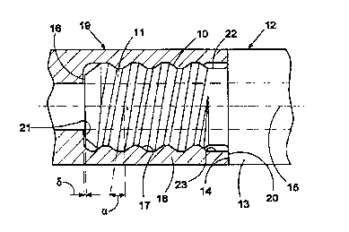
enclosed drawings, where Fig. l ~shows a schematic,
partly sectioned view of a thread coupling according to
5 the invention; Fig . 2 shows a view similar to Fig .1 of
an alternative embodiment of the invention; and Fig. 3
shows a view similar to Fig. l of a further alternative
f~mho~; t of the invention.
10 The thread coupling of Fig. l i~cludes a male thread 10
that i8 provided on a spigot 11 which constitutes an
integral part of a male extension member 12 for
percussive drilli~g. At the imler end of the spigot l
the male extension member 12 is provided with a
15 shoulder 13 that has a first plane contact surface 14
directed towards the free end of the spigot 11.: The
first contact surface 14 has an extension perpendicular
to a longitudinal centre axis 15 o~ the male extension
memher 12.
The free end of the spigot 11 has the shape of a plane
end surf ace 16 that has an extension perperidicular to
the ce~tre axis 15.
25 The thread coupli~g also includes a female thread 17
that is provided in a sleeYe 18 which constitutes an
integral part of a female extension member 19. ~t the
f ree end oi- the sleeve 18 a second plane contact
surface 20 is provided, said second contact surface 20
30 having an extension perpepdicular to the longitudinal
centre axis 15 of the f emale extension member 19, said
longitudinal centre axis co1 nf~ n~ with the centre
axis of the male extension member 12. I~side the sleeve
18 the female extensio~ member l9 has a plane bottom
35 surface 21 that has an extension perpendicular to the
longitudinal centre axis 15.

WO 96l02729 2 1 ~ 2 2 0 4
From Fig. 1 it is evident that in the thread coupling
according to the present invention the f irst contact
surface 14 of the male extension member 12 always
contacts the second contact surface 20 of the sleeve
5 18, i.e. so called shoulder stop is es~hli~Pd.
It is also evident from Fig. 1 that between the end
surface 16 of the spigot 11 and the bottom surface 21
inside the sleeve 18 there is an initial play ~ that
10 ~ minirlly iS chogen to be zero (0) but with a positive
manuf acturing tolerance in the magnitude of one ( 1 ) mm .
After a certain time of use, at the most within 20% of
the length of life for the thread coupling, this play
15 will be eliminated due to wearing-in of the thread
coupling and consequently the thread coupli~g according
to the invention will have both shoulder and bottom
stop .
20 From Fig. 1 it is also evident that at the right end of
the thread coupling a thread clearance 22 of the male
extension member 12 and a thread clearance 23 of the
female extension member 19 are arranged, said
clearances 22, 23 having the aim of evening out bending
25 stresses from manufacturing inaccuracies of the contact
surfaces 14, 20 or the threads. In addition the
clearances 22, 23 even out torsion stresses and
stresses f rom shock or tension waves that pass through
the thread coupling.
In the event that the thread coupling according to the
present invention is between a drill rod and a drill
bit it is favourable that the drill bit constitutes the
male extension member 12 while the drill rod
35 constitutes the female extension member 19. The reason
theref ore is that the region o~ the clearance 22 of the

WO96/02729 21922~4 r~l .
male thread lO is the weake6t portion of the thread
coupling according to the present invention, i.e. if
the coupling collapses it is likely that the ~racture
will occur in the region of the clearance 22. Since a
drill bit i6 worn out up to ten time6 fa6ter than a
drill rod it is favourable that the fracture is located
in the drill bit. _ _
A6 i6 indicated in ~ig.1 the male thread 11 has a pitch
angle (Y. Of cour6e the female thread 17 ha6 the same
pitch angle ~. In accordance with the pre6ent invention
the pitch angle ~ i6 greater that 8.5 and le66 than
15 (8.5~ ~l . Preferably the pitch angle~
6hould be greater than 9.5 and less than 11.5
(9.5< ~ c 11.5~. For thread coupling6 without
6houlder-bottom 6top 6uch pitch angle6 are too great
and the thread-coupling would be un6~ ;r;~nt
tigthened, the con6equence being that pitting6 occur
and the length of life of the threads i6 unacceptable
2 0 6hort .
Due to the 6houlder-bottom 6top in the thread coupling
according to the pre6ent inve~tion the 6hock wave i6
tran6mitted 6imultaneou61y through both the 6pigot 11
and the 61eeve 1~. Thi6 means that there i6 very 6mall
relative motions in the axial r~lrPrt;rn between the
male thread 10 of the 6pigot 11 and the female thread
17 of the 61eeve 18. Thus, the thread coupling
acr--r-1;nrj to the present invention will operate
properly at a lower tirjht.~n~n~ level than thread
coupling6 without shoulder-bottom stop . Said lower
tightening level i6 achieved by an increa6e of the
pitch angle ~.
In the ~mho~;m~nt according to Fig.2 two drill rod6 12
and 12" having two 6pigot6 11' and ll", re~pectively,
_ _ . . _ _ _ ,, ... .. .. _ .

~ WO 96/02729 2 1 9 2 2 0 4 P~
are coupled together by a separate coupling sleeve 18'.
In case the spigot 11 ' i9 considered to belong to the
male extension member then the sleeve 18 ' together with
the drill rod 12 " is considered to constitute the
5 f emale extension member . Since there i8 a play
between the end surfaces il6', 16" of the spiyots 11'
and 11" respectively the end surface 16" is considered
to be the bottom surface of the female extension
member. If on the other hand the spigot 11" is
10 considered to belong to the male extension member then
of course a reversed approach must be used. However, in
the appending claims the spigot 11~ is considered to
belong to the male extension member 12 ~ . As in Fig .1
the end surfaces/bottom surfaces 16', 16' ' have an
15 ~t~nqi~n perpendicular to the longitudinal centre axis
15 .
Also in the embodiment according to Fig. 2 both the male
threads 10', 10" and the female threads 17', 17" have
2 o the same pitch angle ~ .
The r~mhor1;r-nt according to Fig.3 ;noll~r1r~ a male
thread 10' ~ ~that is provided on a separate spigot
. In Fig.3 the male thread 10' ' ' is interrupted in
25 the intermediate region of the longitudinal direction
of the spigot 11' ' ' . However, within the scope of the
present invention it is also possible that the male
thread has a continous extension along the entire
length of the spigot 11' ' ' . Since the spigot 11' ' ' is a
30 separate element there are two end surfaces 16' ' ' and
16 ' ~ ~ ~ respectively .
The spigot 11' ' ' is received in two sleeves 18 ' ~ ' and
18 ~ respectively, said sleeves 18 ' ' ', 18 ' ' ' ' being
35 i~tegral with drill tubes 19' ' ' and 19' ' ' '
respectively. The female threads 17' ' ' and 17' ~ ~ ~ are
~?'

WO 96/027Z9 2 i 9 2 2~ 4 r~
located inside the sleeves 18' ' ' and 18' ' ' '
respectively. Both the male thread lQ' ' ' and the female : ~
threads 17' ~ ~ and 17' ~ ~ ~ have a pitch angle ~. '
5 At the free ~ns~ o~ the ~leeves 18' ~ ~ a~d 18' ~ ~ ~ contact
surfaces 20' ' ' and 20' ' ' ' respectively are arranged. ~:
Inside the sleeves 18' ~ ~ and l=a' ~ ~ ~ planar bottom
surfaces 21' ~ ~ and 21' ~ ~ ~ resFectively are arranged.
The end surfaces 16 ' ' ', 16' ' ' ', the contact surfaces ~
2n' ~ ~, 20' ' ~ ~ and the bottom surfaces 21' ' ~, 21' ~ ~ ~ all
have an extension per,oendicular to the=longitudinal
centre axis 15.
The embodiment of Fig.3 fllnct;t~nq according to the
15 principles of the present invention. First there is
shoulder stop est~hl; ~h~d between the contact surfaces
20 ' ' ' and 20' ' ' ' . Then there are two bottom stops
eatablished when after wearing in of the thread
coupling the plays ~ at both ends of the spigot 11'
2 0 are eliminated .
The invention is in no way restricted to the
embodiments described above. Thus the principles of the
invention can be used both for drill rods and drill
25 tubes for percussive drilling and also in a thread
coupling between a shank adapter and the f irst drill
rod. The threads of a thread coupling according to the
present invention preferably have one ent~y but it is
also possible with two entries. The embodiments and
3 0 examples should not be considered given in a
restricting manner but only for examplifying purposes.
Although the present invention primarily relates to
trapezoidal threads, the present invention is not
35 limited to such type of threa~ds. ~ ~

W0 96/027~9 ~ 1 9 2 2 g 4' r~
Also in other respects the invention can be varied
f reely within the scope of the appending claims .

Dessin représentatif
Une figure unique qui représente un dessin illustrant l'invention.
États administratifs

2024-08-01 : Dans le cadre de la transition vers les Brevets de nouvelle génération (BNG), la base de données sur les brevets canadiens (BDBC) contient désormais un Historique d'événement plus détaillé, qui reproduit le Journal des événements de notre nouvelle solution interne.

Veuillez noter que les événements débutant par « Inactive : » se réfèrent à des événements qui ne sont plus utilisés dans notre nouvelle solution interne.

Pour une meilleure compréhension de l'état de la demande ou brevet qui figure sur cette page, la rubrique Mise en garde , et les descriptions de Brevet , Historique d'événement , Taxes périodiques et Historique des paiements devraient être consultées.

Historique d'événement

Description Date
Le délai pour l'annulation est expiré 1999-07-13
Demande non rétablie avant l'échéance 1999-07-13
Réputée abandonnée - omission de répondre à un avis sur les taxes pour le maintien en état 1998-07-13
Demande publiée (accessible au public) 1996-02-01

Historique d'abandonnement

Date d'abandonnement Raison Date de rétablissement
1998-07-13

Taxes périodiques

Le dernier paiement a été reçu le 1997-06-20

Avis : Si le paiement en totalité n'a pas été reçu au plus tard à la date indiquée, une taxe supplémentaire peut être imposée, soit une des taxes suivantes :

  • taxe de rétablissement ;
  • taxe pour paiement en souffrance ; ou
  • taxe additionnelle pour le renversement d'une péremption réputée.

Les taxes sur les brevets sont ajustées au 1er janvier de chaque année. Les montants ci-dessus sont les montants actuels s'ils sont reçus au plus tard le 31 décembre de l'année en cours.
Veuillez vous référer à la page web des taxes sur les brevets de l'OPIC pour voir tous les montants actuels des taxes.

Historique des taxes

Type de taxes Anniversaire Échéance Date payée
TM (demande, 2e anniv.) - générale 02 1997-07-14 1997-06-20
Titulaires au dossier

Les titulaires actuels et antérieures au dossier sont affichés en ordre alphabétique.

Titulaires actuels au dossier
SANDVIK AB
Titulaires antérieures au dossier
KENNETH LARSSON
Les propriétaires antérieurs qui ne figurent pas dans la liste des « Propriétaires au dossier » apparaîtront dans d'autres documents au dossier.
Documents

Pour visionner les fichiers sélectionnés, entrer le code reCAPTCHA :


Pour visualiser une image, cliquer sur un lien dans la colonne description du document. Pour télécharger l'image (les images), cliquer l'une ou plusieurs cases à cocher dans la première colonne et ensuite cliquer sur le bouton "Télécharger sélection en format PDF (archive Zip)" ou le bouton "Télécharger sélection (en un fichier PDF fusionné)".

Liste des documents de brevet publiés et non publiés sur la BDBC .

Si vous avez des difficultés à accéder au contenu, veuillez communiquer avec le Centre de services à la clientèle au 1-866-997-1936, ou envoyer un courriel au Centre de service à la clientèle de l'OPIC.


Description du
Document 
Date
(aaaa-mm-jj) 
Nombre de pages   Taille de l'image (Ko) 
Abrégé 1996-01-31 1 45
Description 1996-01-31 7 251
Revendications 1996-01-31 2 70
Dessins 1996-01-31 3 59
Dessin représentatif 1997-12-30 1 9
Courtoisie - Lettre d'abandon (taxe de maintien en état) 1998-08-09 1 189
Rapport d'examen préliminaire international 2019-09-18 7 260