Sélection de la langue

Search

Sommaire du brevet 2194146 

Énoncé de désistement de responsabilité concernant l'information provenant de tiers

Une partie des informations de ce site Web a été fournie par des sources externes. Le gouvernement du Canada n'assume aucune responsabilité concernant la précision, l'actualité ou la fiabilité des informations fournies par les sources externes. Les utilisateurs qui désirent employer cette information devraient consulter directement la source des informations. Le contenu fourni par les sources externes n'est pas assujetti aux exigences sur les langues officielles, la protection des renseignements personnels et l'accessibilité.

Disponibilité de l'Abrégé et des Revendications

L'apparition de différences dans le texte et l'image des Revendications et de l'Abrégé dépend du moment auquel le document est publié. Les textes des Revendications et de l'Abrégé sont affichés :

  • lorsque la demande peut être examinée par le public;
  • lorsque le brevet est émis (délivrance).
(12) Demande de brevet: (11) CA 2194146
(54) Titre français: SYSTEME DE SAUVETAGE SERVANT A EVACUER DES BATIMENTS ELEVES
(54) Titre anglais: RESCUING SYSTEM FOR EVACUATION FROM HIGH BUILDING CONSTRUCTIONS
Statut: Réputée abandonnée et au-delà du délai pour le rétablissement - en attente de la réponse à l’avis de communication rejetée
Données bibliographiques
Abrégés

Abrégé français

Boîtier de cordage (1) comportant un perçage de suspension (2) et un espace (3) servant à loger un mécanisme dans lequel une poulie (5) pourvue d'une gorge en V (8) possédant une surface striée, est fixée à un axe central (6) au moyen d'une goupille de verrouillage (7). Une corde (9) est enfilée à travers une ouverture (4) du boîtier (1), passe au-dessus de la poulie (5) et ressort par l'ouverture (4). Un harnais (S1, S2) est fixé à chaque extrémité de la corde (9), afin de porter une personne. La corde (9) se prolonge entre les harnais, de façon à constituer une boucle ininterrompue. Un support de fixation (11) sert à suspendre le boîtier de cordage (1) à une paroi ou à un crochet.


Abrégé anglais


A rope housing (1) with a suspension hole (2) and a space (3) for a mechanism
where a pulley (5) with a V-groove (8) having a corrugated surface is fixed to
a centre axis (6) by help of a locking pin (7). A rope (9) is threaded through
an opening (4) in the rope housing (1), over the pulley (5) and out again
through the opening (4). Each extremity of the rope (9) has a harness (S1, S2)
attached to it to carry a person. The rope (9) is prolonged between the
harnesses so as to form an uninterrupted loop. A fastening bracket (11) is
provided to suspend the rope housing (1) to a wall or a hook.

Revendications

Note : Les revendications sont présentées dans la langue officielle dans laquelle elles ont été soumises.


7
C L A I M S
1. A rescue system for evacuating high buildings, comprising
a rope housing (1) in which a pulley (5) is mounted, and where
a rope is threaded into the housing (1) through an opening
(4), runs over the pulley (5) through a pulley-groove (8), and
out again, and where the incoming and outgoing lengths of rope
(9) through the walls of the rope housing (1) are approximate-
ly parallel running between, characterized by a combination
of the following features: that he pulley is fixed in the
housing (1), the pulley also being fixed in relation to the
rope (9), and that the groove (8) in a manner known per se is
provided with a V-shaped form the narrowest part of which
being nearest the centre of the pulley (5), and the groove has
a rough surface to regulate the friction to the rope sliding.
2. A rescue system of claim 1, characterized in that he
pulley is fixed in the housing (1) by means of a locking pin
(7)~
3._ A rescue system of claims 1 - 2, characterized in that
the pulley (5) is fixed in relation to the opening (4).
4. A rescue system of claim 1, characterized in that the
surface roughness of the groove (8) is provided by
corrugations.
5. A rescue system in accordance with any of the preceding
claims, characterized in that the opening (4) is funnel shaped
and has an inner rough surface while the rope lengths are
mechanically pressed together as they pass through part of the
funnel shape.

8
6. A rescue system in accordance with any of the preceding
claims, characterized in that at each end of the rope (9), a
harness in an manner known per se is provided to carry a
person.
7. A rescue system in accordance with any of the preceding
claims, characterized in that the rope (9) is prolonged
between the harnesses to become an uninterrupted loop and
serves to regulate the speed of descent.
8. A rescue system in accordance with any of the preceding
claims, characterized in that a suspension hole (2) connects
the rope housing (1) to a fastening bracket (11), permitting a
sideways motion of the housing.
9. A rescue system in accordance with any of the preceding
claims, characterized in that a housing cover (10) is provided
to cover the front of the rope housing (1) and is horizontally
wider than the rope housing (1) so that the pulley (5) becomes
an integral part of the rescue system.
10. A rescue system in accordance with any of the preceding
claims, characterized in that a fastening bracket (11)
consisting of a lower half provided with a rope housing hole
(12) placed so as to communicate with the suspension hole (2)
in the rope housing (1), and an upper half provided with holes
for fastening to a wall, for example.
11. A rescue system in accordance with any of the preceding
claims, characterized in that the fastening bracket (11) has
several fastening holes (13) positioned on a non-vertical
line, and a central fastening hole (14).

12. A rescue system in accordance with any of the preceding
claims, characterized in that the upper and the lower halves
of the fastening bracket (11) are positioned in two different
vertical and parallel planes, said planes also being
approximately parallel with the wall on which the fastening
bracket (11) is mounted.

Description

Note : Les descriptions sont présentées dans la langue officielle dans laquelle elles ont été soumises.

~ WO96101136 71 9~ ~ 4 6 r~ >1
? s Rescuing system for evacuation from high building construction~
The present invention relates to a rescue system for use when evacuating
high buildings or the like. The rescue system consists of a rope and a lowering
, a fastening device to the building, and a housing.
In case of fire in high buildings from which escape may be ~Jlul/lellldli., due
to the height, means of escape cam be provided either by ladders put up by people
outside the buildmg, or ladder trucks, or ladders mounted on the building itself,
and which can be released from the desired height by the people preparing to
evacuate the building. Another common piece of equipment is a rescue rope
consistmg of a lowering ' a harness which the person cam slip into, and a
suspension system. This type of rescue rope is normally hanging on a hook by a
window on the inside of the building, amd it can be let out of the window when
needed.
Norwegian Patents 24,690, 41,639 and 43,650 give the description of
lowering .,.~ ' for rescue ropes consisting of a friction pulley in which the
rescue rope runs. Thereafter, the rope runs between several smaller guide pulleys
placed on a board which is itself positioned so as to move around a shaft, and thus
effect a controDed swing motion. The board and the friction pulley are arranged m
such a manner that the friction pulley will stop a number of times per rotation. This
confers mertia to the system and acts as the necessary friction and brake
mechanism for the system. Such devices comprise a large number of moving parts
which are expected to function when needed in a rescue situation, even after long
storage when not in use. They require ,~ and are entirely deprived of a
mechanism which could provide friction as a function of weight. Only some of
those devices feature the possibility of lowering people alternately from both ends
3û of the rope.

2 1 94 ~ 46
WO96/01136 P~ ,5.'~ 121 o
In yet other devices currently available, the rescue rope runs over a puOey.
A rotating arm presses the rope against the puUey and thus provides the desired
S braking effect. The arm also acts as suspension system between the building and
the lowering . ' , and is designed in such a manner that the weight of the
person being rescued provides the required braking moment. Such devices are
described in Norwegian Patent 35,095 and in U.S. Patent 659,093. Those devices
also require to ensure reliable working order in an emergency after
10 long storage when not in use. Those lowering ' allow rescue at one end
of the rope only.
In Norwegian Patent 168,807 a solution was proposed, reducing the
number of moving parts to one single friction pulley in which the rescue rope runs.
The friction pulley has a large diameter centre hole. A circular knob is provided in
15 the centre hole, and a .,u~ r ' . knob is provided on the outer edge of the
friction pulley so that the pulley slides like a flat ring between the knobs. Before
and atter rumling over the friction pulley, thc rescue rope is threaded between two
other knobs placed under the puOey in such a way that a vertical line drawn
through the centre of the knob positioned inside the centre hole will pass between
20 the two knobs placed under the pulley. When a force is exerted on one end of the
rope, the effect of the large centre hole of the pulley relative to the diarneter of the
knob around which it rotates wiO create a force which causes the puOey to rotateand press against the two knobs under it. This action provides a braking force.
However, this device is also composed of moving parts, and is
25 required to keep it in working order at all times. With this device, the rope must be
drawn up again before a new person can be lowered. Rescue ropes of this type
have therefore a reduced capacity in an emergency.
The t~,ullJ~,laLul~" inside and outside a building being rarely equal and the
air having different humidity content, airing the bedroom will cause r~"~
30 to occur on the friction parts of the device mentioned. This wiO result in corrosion

~ WO96101136 ~ 1 9 ~ 3 ~ 6 p~ s~ cl~l
and reduce the mobility of the pulley, with the subsequent risk of jamming when in
use, and the person being rescued remaining hanging against the wali and unable to
get down. Another factor to be taken into account is that the person who uses a
rescue rope of the type proposed in NO-168,807 must hold the opposite part of the
rope to be able to slow down their descent with their hands. Letting go means
ending up in free fali towards the groumd. The device is therefore relatively difficult
to use, and the purpose of such a rescue rope is defeated. The corrosion risk insuch devices argues in disfavour of the use of moving parts in rescue rope systems.
One object of the present invention is to provide a complete rescue system
with a secure mounting to the building, free storage after "
and a reiiable lowering and braking function. It is a further object of the present
invention to combine a free device with the possibiiity of iowering
people aiternately at both ends of the rope for optimum capacity.
This is achieved with a rope housmg in which a pulley is mounted and held
fixed by a locking pin. The pulley is aiso fixed in relation to a rope which is
threaded into the rope housing, over the pulley, and out again through am opening,
and where the incoming and outgomg lengths of rope through the wails of the ropehousing are ~ parailel.
Further details of this invention will become apparent from the following
description of an e ~ - " of the invention.
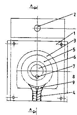
Fig. I is a cross-sectional view of the lowering and braking, '
Fig. 2 is a cross-sectionai view of the same mechanism taken aiong the
iine A-A of Fig. 1.
Fig. 3 iiiustrates the principle of a loop rope between harnesses.
Fig. 4a is a front view of the fastening bracket for the rope housing.
. Fig. 4b is a cross-sectionai view of the fastening bracket of Fig. 4a.

2 1 94 1 46
WO 96/01136 PCT/NO95/00121
This invention is composed of a rope housing I containing a braking
' ~ The rope housing I acts also as suspension device for the entire
5 system, its upper extremity being provided with a suspension hole 2 which is used
to suspend the device of this invention to a wall.
Inside the rope housing 1, a space 3 for the mechanism is provided, having
am upper part of a semi-circular shape and a lower part ~ in the shape
of a rect~mgle. In the side of the rectangle which is furthest removed from the
10 suspension hole 2, an opening 4 is provided p~ di~,ulol to that side. Inside the
space 3 for the ' , a circular pulley 5 is provided, the centre axis 6 of
which is part of the rope housing I . A locking pin 7 is placed between the pulley 5
and the centre axis 6 to prevent the pulley S from rotating.
The pulley 5 is designed with a V-groove 8 in which a rope 9 lies. The
15 surface of the groove 8 is corrugated o} has any other appropriate surface
providing the necessary roughness to increase friction. The rope 9 is threaded into
the space 3 for the mechanism through the opening 4, runs over the pulley 5, andruns out again through the opening 4 parallel with the incoming length of rope.
The opening 4 is funnel shaped and its inside face can be provided with a rough
20 surface. Moreover, the narrowest end of the r ~ ~ap~rl opening has such a
diameter that the incoming and outgoing lengths of the rope 9 will be somewhat
squeezed together, amd a further friction effect is therefore obtained in addition to
the friction between the rope 9 and the pulley 5, thus giving further braking effect.
When one end of the rope 9 outside the rope housing I is pulled down, or
25 when it is weighed down by a person evacuatirig the building, the rope will slide
down into the groove 8 amd the friction between the side walls of the groove amdthe rope 9 will determine how deep down the groove 8 the rope 9 will slide.
The force with which the rope 9 is being pulled upon determines the depth
of the rope 9 inside the groove. A friction mechanism is therefore obtained where
30 the amount of friction is determined by the person's weight, and the velocity of
descent will be the same for any person, regardless of their weight.

~ WO96/01136 2~ 94 1 46 PCI/N09S~00121
When a person has reached the ground with the help of the rope 9, the next
person cam use the other end of the rope to lower themselves. The device of the
5 present invention can therefore be used at optimal capacity when a harness is
attached at each end of the rope 9.
The device of the present invention also offers the possibility of attaching a
baby harness or a carrying bag for babies to the adult harness, thus rncreasing the
capacity.
The device of the present invention comprises no moving part requiring
to ensure reliable function.
Fgure 3 shows the principle by which the rope 9 is prolonged between
harness Sl and harness S2 to give a person lowering himself or herself in one ofthe harnesses the possibility to regulate and decrease their speed of descent by15 holdrng the rope on the opposite side of the pulley 5. Holding the opposite
extremity of the rope 9 will cause the rope 9 to slide deeper into the groove 8 of
the pulley 5 and thus incrcase the braking effect.
Figure 2 iDustrates also a housing cover 10 placed in front of the rope
housing 1, covering the pulley 5, and slightly wider than the rope housing 1. The
20 wider edges are used to attach the outer cover so that the rescue system becomes a
closed unit.
As illustrated rn figure 1, a suspension hole 2 is provided in the rope
housing 1. This aDows the rope housing I to be connected to a fastening bracket
11 illustrated on figures 4a and 4b. A COI~t~lJUlll].llg rope housing hoie 12 is25 provided in the lower half of the fastenmg bracket 11. Such a comnection permits
the rope housmg I to effect a sideways swinging motion about the suspension
point for the fastening bracket 11.
The upper half of the fastening bracket 11 has several types of holes for
mounting the bracket itself and the rescue system to a wall or the like. The
30 mounting holes 13 are provided for mounting the fastening bracket 11 to a timber
wall or structure. The position ofthe mounting holes 13 relative to one another

2 ~ 94 1 46
WO 96/01136 PCT/N095/00121
prevents the timber from splitting during mounting, as a vertical alignment of the
holes is thus avoided.
The central fastening hole 14 is used to suspend the rescue system from a
hook when such a hook is available.
The upper and the lower halves of the fastening bracket 11 are positioned
in such a manner that they stand each in their individual plane, both planes being
parallel to each other. These planes are also ~ , parallel to the plane of
any wall on which the rescue system may be mounted.

Dessin représentatif
Une figure unique qui représente un dessin illustrant l'invention.
États administratifs

2024-08-01 : Dans le cadre de la transition vers les Brevets de nouvelle génération (BNG), la base de données sur les brevets canadiens (BDBC) contient désormais un Historique d'événement plus détaillé, qui reproduit le Journal des événements de notre nouvelle solution interne.

Veuillez noter que les événements débutant par « Inactive : » se réfèrent à des événements qui ne sont plus utilisés dans notre nouvelle solution interne.

Pour une meilleure compréhension de l'état de la demande ou brevet qui figure sur cette page, la rubrique Mise en garde , et les descriptions de Brevet , Historique d'événement , Taxes périodiques et Historique des paiements devraient être consultées.

Historique d'événement

Description Date
Demande non rétablie avant l'échéance 1999-07-05
Le délai pour l'annulation est expiré 1999-07-05
Réputée abandonnée - omission de répondre à un avis sur les taxes pour le maintien en état 1998-07-06
Lettre envoyée 1998-01-21
Exigences de rétablissement - réputé conforme pour tous les motifs d'abandon 1997-12-31
Réputée abandonnée - omission de répondre à un avis sur les taxes pour le maintien en état 1997-07-04
Demande publiée (accessible au public) 1996-01-18

Historique d'abandonnement

Date d'abandonnement Raison Date de rétablissement
1998-07-06
1997-07-04

Taxes périodiques

Le dernier paiement a été reçu le 1997-12-31

Avis : Si le paiement en totalité n'a pas été reçu au plus tard à la date indiquée, une taxe supplémentaire peut être imposée, soit une des taxes suivantes :

  • taxe de rétablissement ;
  • taxe pour paiement en souffrance ; ou
  • taxe additionnelle pour le renversement d'une péremption réputée.

Les taxes sur les brevets sont ajustées au 1er janvier de chaque année. Les montants ci-dessus sont les montants actuels s'ils sont reçus au plus tard le 31 décembre de l'année en cours.
Veuillez vous référer à la page web des taxes sur les brevets de l'OPIC pour voir tous les montants actuels des taxes.

Historique des taxes

Type de taxes Anniversaire Échéance Date payée
Enregistrement d'un document 1996-12-30
Rétablissement 1997-12-31
TM (demande, 2e anniv.) - petite 02 1997-07-04 1997-12-31
Titulaires au dossier

Les titulaires actuels et antérieures au dossier sont affichés en ordre alphabétique.

Titulaires actuels au dossier
INTERSAFE SECURITY A/S
Titulaires antérieures au dossier
HARALD S. HANSEN
Les propriétaires antérieurs qui ne figurent pas dans la liste des « Propriétaires au dossier » apparaîtront dans d'autres documents au dossier.
Documents

Pour visionner les fichiers sélectionnés, entrer le code reCAPTCHA :


Pour visualiser une image, cliquer sur un lien dans la colonne description du document. Pour télécharger l'image (les images), cliquer l'une ou plusieurs cases à cocher dans la première colonne et ensuite cliquer sur le bouton "Télécharger sélection en format PDF (archive Zip)" ou le bouton "Télécharger sélection (en un fichier PDF fusionné)".

Liste des documents de brevet publiés et non publiés sur la BDBC .

Si vous avez des difficultés à accéder au contenu, veuillez communiquer avec le Centre de services à la clientèle au 1-866-997-1936, ou envoyer un courriel au Centre de service à la clientèle de l'OPIC.


Description du
Document 
Date
(aaaa-mm-jj) 
Nombre de pages   Taille de l'image (Ko) 
Description 1996-01-17 6 241
Abrégé 1996-01-17 1 46
Revendications 1996-01-17 3 93
Dessins 1996-01-17 3 55
Dessin représentatif 1998-01-06 1 9
Courtoisie - Lettre d'abandon (taxe de maintien en état) 1997-09-28 1 188
Avis de retablissement 1998-01-20 1 172
Courtoisie - Lettre d'abandon (taxe de maintien en état) 1998-08-02 1 189
Taxes 1997-12-30 1 53
Rapport d'examen préliminaire international 1996-12-29 12 476
Courtoisie - Lettre du bureau 1997-02-03 1 39