Sélection de la langue

Search

Sommaire du brevet 2194668 

Énoncé de désistement de responsabilité concernant l'information provenant de tiers

Une partie des informations de ce site Web a été fournie par des sources externes. Le gouvernement du Canada n'assume aucune responsabilité concernant la précision, l'actualité ou la fiabilité des informations fournies par les sources externes. Les utilisateurs qui désirent employer cette information devraient consulter directement la source des informations. Le contenu fourni par les sources externes n'est pas assujetti aux exigences sur les langues officielles, la protection des renseignements personnels et l'accessibilité.

Disponibilité de l'Abrégé et des Revendications

L'apparition de différences dans le texte et l'image des Revendications et de l'Abrégé dépend du moment auquel le document est publié. Les textes des Revendications et de l'Abrégé sont affichés :

  • lorsque la demande peut être examinée par le public;
  • lorsque le brevet est émis (délivrance).
(12) Brevet: (11) CA 2194668
(54) Titre français: DISTILLATION SOUS VIDE D'UN PRODUIT PETROLIER
(54) Titre anglais: VACUUM DISTILLATION OF A PETROLEUM PRODUCT
Statut: Périmé et au-delà du délai pour l’annulation
Données bibliographiques
(51) Classification internationale des brevets (CIB):
  • B01D 03/10 (2006.01)
  • C10G 07/06 (2006.01)
(72) Inventeurs :
  • ABROSIMOV, ALEXANDR ALEXEEVICH (Fédération de Russie)
  • KOCHEMASOV, ALEXANDR MIKHAILOVICH (Fédération de Russie)
  • KOCHERGIN, IVAN ALEXANDROVICH (Fédération de Russie)
  • TSEGELSKY, VALERY GRIGORIEVICH (Fédération de Russie)
(73) Titulaires :
  • VALERY GRIGORIEVICH TSEGELSKY
(71) Demandeurs :
  • VALERY GRIGORIEVICH TSEGELSKY (Fédération de Russie)
(74) Agent: MARKS & CLERK
(74) Co-agent:
(45) Délivré: 2000-09-12
(86) Date de dépôt PCT: 1994-08-19
(87) Mise à la disponibilité du public: 1996-02-29
Requête d'examen: 1997-05-02
Licence disponible: S.O.
Cédé au domaine public: S.O.
(25) Langue des documents déposés: Anglais

Traité de coopération en matière de brevets (PCT): Oui
(86) Numéro de la demande PCT: PCT/RU1994/000197
(87) Numéro de publication internationale PCT: RU1994000197
(85) Entrée nationale: 1997-01-08

(30) Données de priorité de la demande: S.O.

Abrégés

Abrégé français

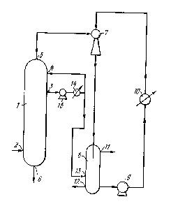
Le procédé de distillation sous vide de l'invention consiste à diviser le produit liquide acheminé jusque dans une cuve sous un vide dans une phase vapeur/gaz ainsi qu'au moins une fraction liquide, à extraire la phase vapeur/gaz de la cuve à l'aide d'un dispositif produisant un vide, et à diviser ensuite la phase vapeur/gaz en une phase gazeuse et une phase liquide par condensation directement dans le dispositif produisant le vide. Une partie de la phase liquide est utilisée en tant que liquide de travail destiné au dispositif produisant le vide. L'installation de distillation sous vide de l'invention comprend une cuve à vide dotée de conduits ainsi qu'un dispositif produisant un vide comportant une soufflante à jet, un séparateur et une pompe, ces éléments étant reliés mutuellement par des conduits.


Abrégé anglais


The proposed vacuum distillation process involves
dividing the liquid product fed into a vessel under a vacuum
into a steam/gas phase and at least one liquid fraction,
removal of the steam/gas phase from the vessel using a
vacuum-producing device, and subsequent division of the
steam/gas phase into a gas and a liquid phase by condensation
directly in the vacuum-producing device. A portion of the
liquid phase is used as a liquid working medium for the
vacuum-producing device. The proposed vacuum distillation
facility-producing device which includes a jet blower,
separator and pump, these elements being interconnected by
pipes.

Revendications

Note : Les revendications sont présentées dans la langue officielle dans laquelle elles ont été soumises.


The embodiments of the invention in which an exclusive property or privilege
is
claimed are defined as follows:
1. A method for vacuum distillation of a petroleum product, comprising:
feeding the petroleum product to a vacuum fractionating column in which the
petroleum
product is separated into a vapour-gaseous phase containing vapours of
petroleum
fractions, at least one liquid fraction, and a residue;
feeding part of the at least one liquid fraction to an upper portion of the
vacuum
fractionating column;
feeding the vapour-gaseous phase to a vacuum-creating device which includes a
liquid-gaseous ejector having an inlet to which a fluid working medium is
delivered;
providing condensation of the vapour-gaseous phase in the vacuum-creating
device to
produce a mixture which consists of a gaseous phase and a liquid phase
comprising a
condensate of petroleum fraction vapours;
separating said mixture into the gaseous phase and the liquid phase and
discharging the
gaseous phase and part of the liquid phase from the vacuum-creating device;
and
using, as part of the fluid working medium in the ejector, a condensate of
petroleum
fraction vapours, formed as a result of the distillation of the petroleum
product, after
preliminary removal of excess heat.
2. The method according to claim 1, in which part of the at least one liquid
fraction is added to the fluid working medium.
3. An apparatus for vacuum distillation of a petroleum product, comprising:
a vacuum fractionating column with lines for feeding the petroleum,
discharching at
least one liquid fraction, and discharging a residue;

a reflex line for feeding part of the least one liquid fraction to the upper
portion of the
column;
a liquid-gaseous ejector having a gas inlet connected to the upper portion of
the column
via a vapour-gaseous line;
a separator, a first inlet of which is connected to an output of the liquid-
gaseous ejector,
in which a gaseous phase and a liquid phase are separated, the gaseous phase
and part of
the liquid phase being discharged; and
a pump having an inlet and an outlet, the inlet of the pump connected with a
liquid outlet
of the separator, the outlet of the pump connected to a liquid inlet of the
liquid-gaseous
ejector;
wherein the fluid working medium supplied to the liquid inlet of the liquid-
gaseous
ejector includes a condensate of petroleum fraction vapours, formed as a
result of the
distillation of the petroleum product, after preliminary removal of excess
heat.
4. The apparatus according to claim 3, in which the liquid output of
separator is connected to the liquid inlet of the liquid-gaseous ejector via a
cooler.
5. The apparatus according to claim 3 or 4, in which the liquid fraction
outlet line of the column is connected to a second inlet of the separator.
6. The apparatus according to claim 5, in which the liquid fraction outlet
line is connected to the second inlet via a cooler.

Description

Note : Les descriptions sont présentées dans la langue officielle dans laquelle elles ont été soumises.


CA 02194668 1999-10-12
Vacuum Distillation of a Petroleum Product
This invention relates to a method and equipment for vacuum distillation of a
petroleum product, and may be used in the petroleum refining industry for
fractionating
of petroleum base stock in a vacuum column.
Equipment for vacuum distillation of petroleum stock is known which includes
a vacuum column equipped with a side section, wherein the reduced pressure is
produced using a jet blower (ejector), and wherein the active (ejecting)
medium used is
steam (LJS-A-2073446 and US-A-2140342).
However, the deficiency of the known method and equipment is in mixing of
petroleum fractions with steam and, accordingly, carrying away by steam a
portion of
petroleum fractions, the latter leading to contaminating of steam and to
reducing the
equipment efficiency.
A method is known for vacuum distillation of a liquid product which comprises
feeding it to a reservoir under vacuum, separating the liquid product in the
reservoir
into gases and vapours of readily volatile fractions and into at least one
liquid fraction,
pumping out from the upper reservoir volume the gases and vapours using a
vacuum-
creating apparatus through a condensing cooler, and discharging them from the
latter
(K.P. Shumski "Vacuum apparatus and equipment in chemical engineering",
Moscow,
Mashinostroyeniye Publishers, 1974, pages 123, 143, 153).
Equipment is known as well for vacuum distillation of petroleum stock which
comprises a vacuum column with lines for feeding the petroleum stock and
removing
the liquid fraction, and a line for removing gases and vapours of easily
volatile (upper)
petroleum fractions from the top of the column, which is connected to a vacuum-
creating device (ejector-type steam pump). The line between the top of the
column and
the vacuum-creating apparatus comprises a cooling condenser (Petroleum refiner
Handbook, Ed. G.A. Lastovkin, Leningrad, Khimiya Publisher, 1989, page 74).

CA 02194668 1999-10-12
2
According to the known method and equipment, the vacuum value in the
column is achieved using ejector-type steam pump, in which the ejecting
(working)
medium used is steam.
The steam mixes with petroleum vapours and decomposition gases, this
resulting in contamination of steam condensate with the former products, and
in
removing by the steam condensate of the top petroleum fractions. Moreover, the
ejector-type steam pump does not provide compression of hydrocarbon gases
which are
not condensed after the cooling condenser to a pressure necessary for feeding
the said
gases to, e.g., fuel collector of petroleum refinery plant. Therefore, the
said gases are to
be flared off if additional compressor equipment is absent.
The condensed matter from vacuum-creating device is delivered to a settling
tank wherein the petroleum product is separated from aqueous condensate.
Settling
tanks represent obvious sources of environmental pollution.
Another shortcoming of the known method and equipment is in condensing of
easily volatile fractions, before the vacuum-creating device, in the cooling
condenser;
this, due to pressure differential in the latter, results either in higher
pressure at the top
of the column leading to reduced yield of volatile (light) products, or to a
power
increase provided for the vacuum-creating device.
US-A-3 579 307 discloses a method for separating a liquid product into a
vapour and liquid fraction used in a vacuum evaporator. The vapour phase is
condensed and adsorbed in a liquid flow in an ejector which creates vacuum in
the
evaporator. In this method, however, the working fluid fed to the ejector is
water or
water mixed with a small amount of a condensate of a gaseous monomer
evaporated in
the evaporator. Therefare, to reduce the monomer concentration in the working
fluid,
which tends to increase, the working fluid has to be constantly diluted with
water,
which is unacceptable if an environment-friendly method is to be achieved.
The object of the invention is to create a method and equipment for vacuum
distillation of a liquid petroleum product which could provide intensification
of the
vacuum distillation by producing a closed circuit vacuum-creating device, in
order to
reduce environmental pollution and to reduce power consumption, along with
equipment efficiency increase.

CA 02194668 1999-11-15
~~h
The invention provides a method for vacuum distillation of a petroleum
product,
comprising: feeding the petroleum product to a vacuum fractionating column in
which the
petroleum product is separated into a vapour-gaseous phase containing vapours
of
petroleum fractions, at least one liquid fraction, and a residue; feeding part
of the at least
one liquid fraction to an upper portion of the vacuum fractionating column;
and feeding
the vapour-gaseous phase to a vacuum-creating device which includes a liquid-
gaseous
ejector having an inlet to which a fluid working medium is delivered;
providing
condensation of the vapour-gaseous phase in the vacuum-creating device to
produce a
mixture which consists of ;~ gaseous phase and a liquid phase comprising a
condensate of
to petroleum fraction vapours; separating the mixture into the gaseous phase
and the liquid
phase and discharging the gaseous phase and part of the liquid phase from the
vacuum-
creating device; and using as a part of the fluid working medium in the
ejector a
condensate of petroleum fraction vapours, formed as a result of the
distillation of the
petroleum product, after preliminary removal of excess heat.
It is preferable to refresh the fluid working medium by adding thereto at
least a
portion of the liquid fraction from the column.
The invention also provides an apparatus for vacuum distillation of a
petroleum
product, comprising: a vacuum fractionating column with lines for feeding the
petroleum,
discharching at least one liquid fraction, and discharging a residue. A reflux
line feeds
2o part of the least one liquid fraction to the upper portion of the column. A
liquid-gaseous
ejector has a gas inlet connected to the top portion of the column via a
vapour-gaseous
line. The apparatus also includes a separator, a first inlet of which is
connected to an
output of the liquid-gaseous ejector, in which a gaseous phase and a liquid
phase are
separated, the gaseous phase and part of the liquid phase being discharged;
and a pump
having an inlet and an outlet, the inlet of the pump connected with a liquid
outlet of the
separator, the outlet of the pump connected to a liquid inlet of the liquid-
gaseous ejector.
The fluid working medium supplied to the liquid inlet of the liquid-gaseous
ejector
includes a condensate of petroleum fraction vapours, formed as a result of the
distillation
of the petroleum product, after preliminary removal of excess heat.

CA 02194668 1999-10-12
4
It is advisable to place a cooler between the liquid inlet of the ejector and
the
liquid outlet of the separator to remove excess heat from the liquid phase.
The connection of an additional separator inlet with the line for removing
fluid
fraction from the column provides refreshing of the fluid working medium with
liquid
fraction drawn from the column into the closed circuit of the vacuum-creating
device.
The method for vacuum distillation of the petroleum product and the equipment
provide effective removal of vapour-gaseous phase from the upper portion of
the
column followed with i.ts condensation both in the flow part of the ejector
and in the
line after the ejector. The uncondensed gases (hydrocarbon gases) are
simultaneously
compressed to the pressure required for a user. The compression provides
delivery
from the separator of a hydrocarbon gas under pressure which may be used for
technology requirements, and the excess of the liquid phase may be delivered
as an
intermediate product far further technological processing. In contrast to the
prior art,
the method does not include mixing of the top petroleum fractions with water
and
expulsion of condensat~ and hydrocarbon gases to the environment. Thus, the
method
is an ecologically pure one.
Moreover, the method makes it possible not to use a cooling condenser, for
vapours of light petroleum fractions, in the line which connects the upper
portion of the
column with the vacuum-creating device, because condensation of the light
petroleum
fractions' vapours takes place in the ejector. The method also provides a
reduction of
the external circulation reflux rate of the column top, resulting in reduction
of pressure
difference there, and finally leads to a pressure reduction in the bottom of
the column,
this providing an increased yield of the low-boiling (light) products of
vacuum
distillation.
Such a method and construction of the equipment for vacuum distillation of a
petroleum product provides a substantive decrease in environment
contamination,
decreased power consumption and, accordingly, an increase in the output of the
equipment.
The invention is further described, by way of example, with reference to the
accompanying drawing, schematically showing equipment for vacuum distillation
of a
petroleum product.

CA 02194668 1999-10-12
The equipment contains a rectifying (fractionating) vacuum column 1 equipped
with a line 2 for feeding heated liquid product (petroleum stock), a liquid
fraction
output line 3, an external circulation reflux line 4, a vapour-gaseous phase
output line 5,
and a line 6 for output of the column bottoms. The line 5 connects the column
top 1
with a liquid-gaseous ejector 7 which is connected in series with a separator
8 and a
pump 9. The ejector 7.. separator 8, and pump 9 constitute a vacuum-creating
device,
wherein the gas input of the ejector 7 is connected with the vapour-gaseous
phase
output line 5, the liquid input of the ejector 7 is connected with the output
of the pump
9, the output of the ej ector 7 is connected with the input of the separator
8, and the
liquid output of the separator 8 is connected with the input of the pump 9.
A cooler 10 is mounted in the line between the liquid output of separator 8
and
the liquid input of the ejector 7. The separator 8 is connected by a line 11
with the
consumer's fuel system and by a line 12 with the petroleum product receiver
(neither of
which are shown). An additional input of the separator 8 is connected with the
liquid
fraction output line 3 of the column 1 by means of a line 13 for additional
feeding of
the vacuum-creating device with a liquid fraction from the column 1. A cooler
14 and a
pump 15 are mounted in the line 3. The output of the cooler 14 is connected
with the
column 1 by the reflux line 4.
The vacuum distillation of a liquid product is carried out as follows.
The heated liquid product (petroleum stock) is fed to the column 1 under a
pressure of 1.3 - 8.0 kF'a (10 - 60 mm Hg) via the input line 2. The liquid
fraction
(vacuum gas oil) is discharged via the output line 3, passes through the pump
15, is
cooled in the cooler 14, and is then divided into two flows, one of which
flows via the
line 4 is directed to the external circulating reflux of the upper column
portion, and the
other flow is directed via the line 13 through an additional input of the
separator 8 of
the vacuum-creating device. The liquid phase is gradually saturated with
decomposition gases (hydrocarbon gases) evacuated from the upper column
portion,
this reducing vacuum extent in the column due to evolution of the said gases
in the
ejector nozzle. The latter causes energy consumption at the liquid phase pump
of the
vacuum-creating device. Therefore, in order to produce better vacuum, and to
reduce
power consumption in creating the latter, the liquid phase circulating in the
vacuum-

CA 02194668 1999-10-12
6
creating device is gradually refreshed using the liquid fraction coming from
the column
to the closed circuit of the vacuum-creating device.
From the top column portion, via the output line S, the vapour-gaseous phase
is
discharged, being sucked off by the liquid-gas ejector 7 by means of the
energy of
liquid phase circulating in the closed circuit due to the pump 9. In the
cooler 10 of the
vacuum-creating device, excess heat is removed from the liquid phase, which
excess is
partially formed due to :mechanical energy dissipation in the circuit of
circulating liquid
phase, and partially due to condensation and to cooling of the uncondensed gas
which is
sucked off from the column 1 by the liquid-gas ejector 7, thus providing
temperature
stabilization.
At the output of the liquid-gas ej ector 7, due to energy transmission from
the
active liquid phase to the passive vapour-gaseous phase coming via the line S
from the
upper portion of the column 1, a two-phase mixture is formed having a pressure
of
greater than 0.11 MPa, which is fed to the separator 8. The final condensation
of the
vapour phase takes place in the mixture, which phase has not condensed in the
flow-
through part of the ejector 7. The mixture is divided in the separator 8 of
the vacuum-
creating device to form a gas phase and a liquid phase. The gas phase via the
mains 11
is fed to the consumer's fuel system (not shown). The liquid phase, partially
refreshed
with the liquid fraction {vacuum gas oil) from the column 1, is directed to
the pump 9
input. The liquid phase excess formed due to condensed vapours delivered to
the
ejector 7 from the upper portion of column 1, as well as due to the flow via
the liquid
fraction line 13, is delivered via the line 12 to the petroleum products
receiver (not
shown). During the start-up period of the vacuum-creating device the working
medium
used is any working fluid which is similar by its chemical and physical
properties with
the liquid phase, which phase is comprised of vapour condensate and the liquid
fraction
fed via the line 3. But gradually the initial working fluid is replaced by the
mixture of
vapour condensate and of the liquid fraction accumulated in the separator 8.
The line 6
is used for discharge of the heavy fraction from vacuum distillation.
Thus, the suggested method and equipment for vacuum distillation of a product
suggest the solution of actual problems in petroleum refining industry: the
ecologically
friendly technology of vacuum petroleum refining is realised, financial
expenses are

CA 02194668 1999-10-12
reduced for obtaining vacuum in a column, and the yield of light fractions is
increased
resulting from vacuum distillation of petroleum products.

Dessin représentatif
Une figure unique qui représente un dessin illustrant l'invention.
États administratifs

2024-08-01 : Dans le cadre de la transition vers les Brevets de nouvelle génération (BNG), la base de données sur les brevets canadiens (BDBC) contient désormais un Historique d'événement plus détaillé, qui reproduit le Journal des événements de notre nouvelle solution interne.

Veuillez noter que les événements débutant par « Inactive : » se réfèrent à des événements qui ne sont plus utilisés dans notre nouvelle solution interne.

Pour une meilleure compréhension de l'état de la demande ou brevet qui figure sur cette page, la rubrique Mise en garde , et les descriptions de Brevet , Historique d'événement , Taxes périodiques et Historique des paiements devraient être consultées.

Historique d'événement

Description Date
Le délai pour l'annulation est expiré 2012-08-20
Lettre envoyée 2011-08-19
Inactive : Grandeur de l'entité changée 2004-08-05
Inactive : Page couverture publiée 2000-11-08
Inactive : Correction selon art.8 Loi demandée 2000-10-26
Accordé par délivrance 2000-09-12
Inactive : Page couverture publiée 2000-09-11
Préoctroi 2000-06-07
Inactive : Taxe finale reçue 2000-06-07
Un avis d'acceptation est envoyé 2000-01-19
Lettre envoyée 2000-01-19
Inactive : Approuvée aux fins d'acceptation (AFA) 1999-12-07
Retirer de l'acceptation 1999-11-29
Inactive : Lettre officielle 1999-11-29
Modification reçue - modification volontaire 1999-11-15
Lettre envoyée 1999-11-10
Un avis d'acceptation est envoyé 1999-11-10
Inactive : Approuvée aux fins d'acceptation (AFA) 1999-10-22
Modification reçue - modification volontaire 1999-10-12
Inactive : Dem. de l'examinateur par.30(2) Règles 1999-04-20
Inactive : Dem. traitée sur TS dès date d'ent. journal 1997-06-23
Inactive : Renseign. sur l'état - Complets dès date d'ent. journ. 1997-06-23
Exigences pour une requête d'examen - jugée conforme 1997-05-02
Toutes les exigences pour l'examen - jugée conforme 1997-05-02
Exigences pour l'entrée dans la phase nationale - jugée conforme 1997-01-08
Inactive : Acc. réc. RE - Pas de dem. doc. d'antériorité 1996-06-26
Demande publiée (accessible au public) 1996-02-29

Historique d'abandonnement

Il n'y a pas d'historique d'abandonnement

Taxes périodiques

Le dernier paiement a été reçu le 2000-06-28

Avis : Si le paiement en totalité n'a pas été reçu au plus tard à la date indiquée, une taxe supplémentaire peut être imposée, soit une des taxes suivantes :

  • taxe de rétablissement ;
  • taxe pour paiement en souffrance ; ou
  • taxe additionnelle pour le renversement d'une péremption réputée.

Les taxes sur les brevets sont ajustées au 1er janvier de chaque année. Les montants ci-dessus sont les montants actuels s'ils sont reçus au plus tard le 31 décembre de l'année en cours.
Veuillez vous référer à la page web des taxes sur les brevets de l'OPIC pour voir tous les montants actuels des taxes.

Historique des taxes

Type de taxes Anniversaire Échéance Date payée
Requête d'examen - petite 1997-05-02
TM (demande, 3e anniv.) - petite 03 1997-08-19 1997-06-26
TM (demande, 4e anniv.) - petite 04 1998-08-19 1998-08-12
TM (demande, 5e anniv.) - petite 05 1999-08-19 1999-07-20
Taxe finale - petite 2000-06-07
TM (demande, 6e anniv.) - petite 06 2000-08-21 2000-06-28
TM (brevet, 7e anniv.) - petite 2001-08-20 2001-07-12
TM (brevet, 8e anniv.) - générale 2002-08-19 2002-06-25
TM (brevet, 9e anniv.) - générale 2003-08-19 2003-07-15
TM (brevet, 10e anniv.) - petite 2004-08-19 2004-07-22
TM (brevet, 11e anniv.) - petite 2005-08-19 2005-07-29
TM (brevet, 12e anniv.) - petite 2006-08-21 2006-07-25
2006-07-25
TM (brevet, 13e anniv.) - générale 2007-08-20 2007-08-14
TM (brevet, 14e anniv.) - générale 2008-08-19 2008-08-14
TM (brevet, 15e anniv.) - générale 2009-08-19 2009-08-06
TM (brevet, 16e anniv.) - générale 2010-08-19 2010-08-05
Titulaires au dossier

Les titulaires actuels et antérieures au dossier sont affichés en ordre alphabétique.

Titulaires actuels au dossier
VALERY GRIGORIEVICH TSEGELSKY
Titulaires antérieures au dossier
ALEXANDR ALEXEEVICH ABROSIMOV
ALEXANDR MIKHAILOVICH KOCHEMASOV
IVAN ALEXANDROVICH KOCHERGIN
Les propriétaires antérieurs qui ne figurent pas dans la liste des « Propriétaires au dossier » apparaîtront dans d'autres documents au dossier.
Documents

Pour visionner les fichiers sélectionnés, entrer le code reCAPTCHA :


Pour visualiser une image, cliquer sur un lien dans la colonne description du document (Temporairement non-disponible). Pour télécharger l'image (les images), cliquer l'une ou plusieurs cases à cocher dans la première colonne et ensuite cliquer sur le bouton "Télécharger sélection en format PDF (archive Zip)" ou le bouton "Télécharger sélection (en un fichier PDF fusionné)".

Liste des documents de brevet publiés et non publiés sur la BDBC .

Si vous avez des difficultés à accéder au contenu, veuillez communiquer avec le Centre de services à la clientèle au 1-866-997-1936, ou envoyer un courriel au Centre de service à la clientèle de l'OPIC.

({010=Tous les documents, 020=Au moment du dépôt, 030=Au moment de la mise à la disponibilité du public, 040=À la délivrance, 050=Examen, 060=Correspondance reçue, 070=Divers, 080=Correspondance envoyée, 090=Paiement})


Description du
Document 
Date
(aaaa-mm-jj) 
Nombre de pages   Taille de l'image (Ko) 
Revendications 1996-02-28 2 66
Description 1996-02-28 9 415
Abrégé 1996-02-28 1 20
Dessins 1996-02-28 1 10
Dessin représentatif 2000-08-30 1 4
Dessin représentatif 1997-09-24 1 7
Description 1999-10-11 7 329
Revendications 1999-10-11 2 67
Description 1999-11-14 7 331
Revendications 1999-11-14 2 70
Accusé de réception de la requête d'examen 1996-06-25 1 170
Avis du commissaire - Demande jugée acceptable 1999-11-09 1 164
Avis du commissaire - Demande jugée acceptable 2000-01-18 1 166
Avis concernant la taxe de maintien 2011-09-29 1 170
Correspondance 2000-06-06 1 34
PCT 1997-01-07 16 605
Correspondance 1999-11-28 1 20
Correspondance 2000-10-25 1 30
Paiement de taxe périodique 1997-01-07 1 51