Note : Les descriptions sont présentées dans la langue officielle dans laquelle elles ont été soumises.
2196251
io
MULTI-MODE CAVITY FOR WAVEGUIDE FILTERS, INCLUDING AN ELLIPTICAL
WAVEGUIDE SEGMENT
The invention described herein relates to a multimode cavity with the
characteristics stated in the preamble of Claim 1.
2o A dual-mode cavity with such characteristics is described, for example, in
EP-A-0
687 027 in the name of the same Applicant. That previous document can usefully
serve
as a reference to illustrate the general problems inherent to manufacturing
such
cavities, particularly with regard to the possibility of making waveguide
filters suitable
for being completely designed through computer aided design techniques, with
no need
for specific calibration operations like the ones required by conventional
cavities fitted
with tuning and coupling screws.
In particular, EP-A-0 687 027 discloses a cavity comprising three coaxial
waveguide segments arranged in cascade along the main axis of the cavity. The
two
end segments (with circular, square or rectangular cross section) allow for
two modes
3o to resonate, which modes have linear polarisation parallel and respectively
perpendicular to a reference plane essentially identified by the diametral
plane parallel
to the major dimension of the iris used to couple the modes into the cavity.
The
intermediate segment consists of a waveguide with rectangular cross section
whose
sides are inclined by a given angle with respect to the aforesaid reference
plane.
Such a cavity can be included in a microwave band-pass filter to be used, for
instance, in satellite communications.
A dual-mode cavity without tuning and coupling screws is also disclosed in JP-
A-
60 174501. Elimination of the screws is made possible by the cavity having a
2~9b257
rectangular cross section bevelled in correspondence with a corner, or a
similarly
deformed elliptical cross section. The structure is apparently simpler than
that disclosed
in EP-A-0 687 027, yet the cross-sectional deformation with respect to an
exactly
rectangular or elliptical shape results in very great numerical difficulties
in analytically
modelling the behaviour of the cavity itself. Thus it is very difficult to
obtain the required
accuracy in the design of the cavity and hence, once the cavity is
manufactured, its
operation will not be satisfactory.
The purpose of the present invention is to provide a multi-mode cavity which:
- allows for two or three electromagnetic modes to resonate (with the
consequent
1o possibility of using the same cavity several times in making filters, thus
reducing the
number of geometrical shapes involved);
- do not require coupling and tuning screws and
- can be easily and very precisely designed and manufactured with computer
aided
design techniques.
This purpose is reached thanks to a cavity comprising at least one waveguide
segment and one iris to couple modes into the cavity, which iris identifies
with a main
axis of the cavity a reference plane, wherein said waveguide segment has
elliptical
cross section and it is arranged so that the axes of said elliptical cross
section are
inclined by a given angle with respect to said reference plane, said cavity
therefore
2o allowing for at least two transverse resonant modes orthogonal to each
other, to
resonate.
Arranging a cavity inclined with respect to a reference plane is well known in
the
art. Examples are disclosed in US-A 3,235,822 (De Loach) and US-A 4,513,264
(Dorey
et al.). Both documents disclose a filter comprising a plurality of cavities
each made by
a single rectangular waveguide segment, where the waveguide segments may be
inclined with respect to one another.
In US-A-3,235,822 inclination is used to vary the amount of coupling between
two
adjacent cavities between a maximum and a minimum value. The cavities are
strictly
single-mode cavities. Increasing the shorter dimension of the rectangular
cross section
3o so as to give a nearly-square cross section (as it would be required for
dual-mode
operation) would result in a loss of control over the transmission
characteristics of the
filter, making it impossible to obtain useful electrical responses from the
filter.
Moreover, for very narrow bandwidths, such as the ones the present invention
is
concerned with, tuning screws are to be provided. In the present invention,
inclination
of the cavity is one of the features allowing generation and control of
coupling between
different modes within the cavity without need of using coupling and tuning
screws.
In US-A-4,513,264 the first cavity is aligned with the input field and
inclination of
the second cavity is used to generate diagonal couplings between adjacent
cavities.
3 21 X6257
Coupling between the two modes and tuning is obtained by screws. In the
present
invention, inclination of the first (or the sole) cavity is the feature
allowing generation
and control of coupling between the modes within the cavity without need of
using
screws. Elimination of the screws in the filter according to US-A-4,513,264
would
destroy any possibility of operation of the filter since it would cancel
coupling between
the modes, thus making impossible for the energy to propagate towards the
output.
Inclination of the first cavity would destroy the equi-ripple character of the
passband
response of the filter, and then the objects of the invention disclosed in
such document
cannot be attained.
io The invention shall now be described, purely by way of non limiting
example,
referring to the enclosed drawings, wherein:
- Figure 1 is a perspective view of a prior art cavity according to EP-A-0 687
027,
- Figure 2 is a perspective view of a cavity according to the invention,
- Figure 3 is a cross-sectional view taken along line II-II in Figure 2, and
i5 - Figures 4 and 5 depict the application of the invention to the
manufacture of a triple-
mode cavity.
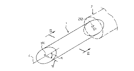
The formalism adopted to represent the cavity, indicated as a whole by 1, is
wholly similar to that adopted in EP-A-0 687 027. As is evident to the
technician skilled
in the art, such a representation shows the geometry of the volume of the
cavity itself,
2o which usually is manufactured within a body of conducting, typically
metallic, material,
with working processes such as turning, electrical discharge machining, etc.
The
related manufacture criteria are widely known to the technicians skilled in
the art and do
not require to be illustrated specifically herein, especially since they are
not in
themselves relevant for the purpose of understanding the invention.
25 It will also be appreciated that, for the sake of clarity, the cavity has
been
represented in the perspective views by enhancing its extension along the main
longitudinal axis (axis Z) with respect to the actual constructive embodiment:
differently
stated, in practice, the cavity will usually be longitudinally "squashed" with
respect to
the shape shown. It should in any case be specified that the lengths of the
individual
3o sections of the cavity constitute design parameters for the cavity itself,
as is well known.
Figure 1 depicts a dual-mode cavity for making microwave band-pass filters,
like
that disclosed in EP-A-0 687 027. In short, that cavity comprises three
coaxial
waveguide segments arranged in cascade along the main cavity axis Z.
Specifically,
there is a first waveguide element CC1 with circular cross section followed by
a second
35 waveguide element CR1 with rectangular cross section and then by a third
waveguide
element CC2, again with circular cross section. Reference IR1 indicates an
iris allowing
coupling of the modes into cavity 1, and reference IR2 indicates an iris
arranged so as
to couple multiple modes simultaneously (for instance a cross-shaped iris)
located at
2196257
4
the opposite end of cavity 1. Iris IR2 allows coupling cavity 1 with a cavity
(identical or
different, not shown), arranged in cascade, to make a microwave filter.
The presence of waveguide segment CR1 with rectangular cross section, the
sides of which are inclined by a given angle with respect to a reference plane
which
passes through axis Z and is parallel to the major dimension of iris IR1 and
of the
horizontal element of iris IR2, makes the cavity shown in Figure 1 able to
allow for two
electromagnetic modes to resonate: such modes are transverse with respect to
axis Z
and have polarisation planes respectively parallel and orthogonal with respect
to the
aforesaid reference plane. The non-homogeneous cross-sectional shape of the
cavity
to along axis Z (and the resulting discontinuity) allows tuning and coupling
screws to be
dispensed with. For a more precise description of the manufacturing criteria
of this
known cavity, particularly in regard to the possibility of replacing circular
segments CC1
and CC2 with segments having square or rectangular cross sections, reference
can be
made to the specification of EP-A-0 687 027.
The solution according to the present invention is based on the ascertainment
of
the fact that a dual-mode operation wholly similar to the one attained in the
prior art
solution depicted in Figure 1 can be obtained with the cavity having the
structure shown
in Figure 2. That cavity, still denoted by reference numeral 1, comprises a
waveguide
segment with elliptical cross section, with semiaxes a, b arranged at an angle
with
2o respect to the reference plane, as illustrated in greater detail in the
sectional view of
Figure 3, where the reference plane, denoted ~, is identified by the trace of
its
intersection with the plane of the sheet.
Applicant's experiments have demonstrated that the coupling and tuning of the
two TE resonant modes of the cavity, orthogonal to each other, can be defined
with a
z5 high degree of precision in the course of the design (typically by using a
computer) and
then directly obtained during manufacturing, without need for adjustments, by
controlling the value of the inclination angle (a), the ratio between semiaxes
a and b
("aspect ratio") and the length of the waveguide segment with elliptical cross-
section.
Cavity 1 can be coupled, for example through iris IR2, with another cavity 2,
also
3o with elliptical cross section (whose profile is sketched in dashed lines in
Figure 2), with
a different inclination angle a from that of cavity 1. Thus, a microwave
filter comprising
multiple resonant cavities coupled with each other can be made according to
criteria
known in themselves.
The invention illustrated in Figure 2 can be further developed to give rise to
a
35 triple-mode cavity, i.e. a cavity with the ability to make resonate, in
addition to the two
TE modes mentioned previously, also a third TM mode with electrical field
polarisation
directed along the main axis Z of cavity 1 and orthogonal to the previous
ones. This
A
s 2196251
result can be obtained by providing a waveguide element (comprising a
waveguide
segment or an iris) which introduces a non-axial discontinuity typically near
one end of the
cavity.
In a first embodiment of the triple-mode cavity according to the invention,
shown
s in Figure 4, this is obtained by providing, at one or both ends of an
elliptical waveguide
segment like the one constituting dual-mode cavity 1 shown in Figure 2, a
rectangular
waveguide segment (the term "rectangular" also includes, as a particular case,
a
square cross section) arranged eccentrically (i.e. dissymmetrically or off-
axis) with
respect to axis Z: in other words, that segment is arranged in such a way that
at least
to one of the ideal median planes dividing in half the sides of the cross
section of the
waveguide segment itself is spaced apart by a predetermined offset amount
(aoff) from
main axis Z of the cavity, and in particular from reference plane ~.
By way of example, Figure 4 shows the case of two waveguide segments CR2,
CR3 with rectangular cross section located at the two ends of an elliptical
waveguide
1s segment 1. Should the application make it advisable, one of the rectangular
segments
might be arranged along the body of cavity 1, in an intermediate position
between two
elliptical segments. The or each rectangular waveguide segment can be oriented
so
that its sides are respectively parallel and perpendicular to reference plane
~.
In alternative, the or each eccentric segment could have circular or
elliptical cross
20 section.
In a second embodiment of the triple-mode cavity according to the invention,
shown in Figure 5, the waveguide element that introduces a non-axial
discontinuity is
iris IR1 arranged eccentrically (i.e. dissymmetrically or off-axis) with
respect to axis Z,
that is to say (as can be seen in the drawing) in such a way that the
intersection point of
25 the diagonals of the iris is displaced by a predetermined amount aoff with
respect to the
main axis of the elliptical cavity.
In the case of the triple-mode cavity, too, it is possible to couple cavity 1
with at
least another cavity to make a filter.
Of course, while maintaining unchanged the principles of the invention,
3o construction details and the embodiments of invention may be widely varied
with
respect to what has been described and illustrated, without departing from the
scope of
the present invention. This applies in particular to the possible loading of
the cavity with
a dielectric element in order to reduce the resonance frequency or the volume
of the
cavity. In any case, coupling the orthogonal modes by means of a waveguide
segment
3s with elliptical cross section allows easy modelling and mechanical
manufacturing of the
cavity and of the related filter. In particular, very accurate computation
algorithms exist
to analyse the cavity elements described herein as a function of the related
parameters
(aspect ratio a/b, inclination angle a, etc.). Thus it is possible to use
algorithms to
A
2196257
obtain the complete design of the dimensions of the cavity, with no further
need for
tuning the device thus manufactured.