Note : Les descriptions sont présentées dans la langue officielle dans laquelle elles ont été soumises.
_. ~ 198530
BACKGROUND OF THE INVENTION
The invention relates to self-expanding stmt
delivery systems which are used to implant a stmt into a body
lumen of a patient to maintain the patency of the lumen. The
stent delivery system is useful in the treatment and repair of
body lumens that are damaged or affected by disease, including
coronary arteries, renal arteries, carotid arteries, and other
body lumens.
Stems are generally cylindrically-shaped devices
which function to hold open and sometimes to expand a segment
of a blood vessel or other body lumen. They particularly are
suitable for use to support and hold back a dissected arterial
lining which can occlude the fluid passageway therethrough.
Stems also are useful in maintaining the patency of a body
lumen, such as a coronary artery, after a percutaneous
transluminal coronary angioplasty (PTCA) procedure or an.
atherectomy procedure to open a stenosed area of the artery.
A variety of devices are known in the art for use as
stents and include coiled wires in a variety of patterns that
are expanded after being placed intraluminally by a balloon
catheter; helically wound coil springs manufactured from an
expandable heatsensitive material such as nickel-titanium; and
self-expanding stems that are introduced into the body lumen
in a compressed state and shaped in a zig-zag pattern.
Commonly, the prior art stems are delivered
intraluminally through a percutaneous incision made in a
femoral or renal artery. A stmt is mounted on the distal end
of an elongated catheter, typically on the balloon portion of
a catheter, and the catheter and stent are advanced
intraluminally to the site where the stent is to be implanted.
With expandable stems, the balloon portion of the catheter is
inflated to expand the stmt radially outwardly into contact
with the arterial wall, whereupon the stent undergoes plastic
deformation and remains in an expanded state to hold open and
support the artery.
With respect to self-expanding stems, it has been
known to provide a retractable sheath, which is positioned over
the self-expanding stmt mounted on the distal end of a
CA 02198530 1999-12-09
-2-
catheter. When the catheter has been advanced
intraluminally to the site where the stmt is to be
implanted, the sheath is withdrawn, allowing the self-
expanding stmt to expand radially outwardly into contact
with the arterial wall, thereupon holding open and
supporting the artery.
One of the problems associated with the prior art
stems and catheter-delivery systems is encountered in the
means by which the stmt is removably attached to the
distal end or balloon portion of a catheter. Frequently,
the means employed are insuf f icient to prevent the stmt
from being dislodged or from moving axially along the
catheter or the balloon, movement which compromises the
ability of the clinician to accurately and reliably deploy
the stmt at the desired location in the body lumen.
What has been needed and heretofore unavailable
is a reliable catheter-delivery system on which the stmt
can be mounted and removably attached so that it does not
move axially on the catheter either during delivery and
advancement through the vascular system, or during
implantation of the stmt. The present invention satisfies
this need.
SUMMARY OF THE INVENTION
The present invention is directed to a self
expanding stmt delivery system in which a self-expanding
stmt is removably attached to a catheter so that the stmt
remains in its position on the catheter until it is
implanted. Unlike prior art stems, which may have a
tendency to dislodge from the distal end of the catheter or
to move axially on the catheter shaft when a protective
sheath is withdrawn or when the catheter is advanced
through a tortuous vasculature, the present invention
provides means for removably attaching the stmt to the
catheter so that it is prevented from moving axially on the
catheter shaft.
The present invention provides a catheter
assembly comprising:
CA 02198530 1999-12-09
-3-
an elongated catheter having a proximal end and
a distal end;
the catheter having an inner member and an outer
member extending along a longitudinal axis, the inner
member and the outer member having a coaxial configuration
and dimensioned for relative axial movement;
means for providing relative axial movement
between the inner member and the outer member;
a self-expanding stmt having an open lattice
structure configured to be biased from a delivery
configuration having a reduced cross section and
predetermined length to an open configuration with an
enlarged cross section and being positioned within a distal
end of the outer member in the delivery configuration; and
a plurality of attachment proj ections at a distal
end of the inner member spaced along the stmt a distance
at least as great as the predetermined length for
facilitating the removable attachment of the stmt to the
inner member distal end.
The present invention includes an inner member
that is naturally pliable and deformable or, alternatively,
that is heat-deformable and formed from a polymeric
material which, when heated, will fill the open lattice
structure of the stmt with attachment projections. The
inner member can be formed from polymeric materials
selected from the group of materials consisting of
polyurethanes, polyethylenes, polyethylterphthalate, and
nylons.
In another embodiment of the invention, an
elastomeric sleeve is attached to the distal end of the
inner member. This stmt is mounted on the distal end of
the outer member and is biased outwardly against the outer
member. The inner member distal end and its sleeve are
positioned within the stmt, and the sleeve is heated until
it fills and forms attachment projections in the open
lattice structure of the stent.
The invention also relates to the method of
CA 02198530 1999-12-09
-4-
mounting the self-expanding stmt on the delivery catheter.
The present invention provides a method of
mounting an intravascular stmt on a delivery catheter, the
method comprising:
providing a delivery catheter having an elongated
catheter body and a proximal end and a distal end, the
catheter having an inner member and an outer member
extending along a longitudinal axis, the inner member and
the outer member having a coaxial configuration and
dimensioned for relative axial movement, and control
handles for providing relative axial movement between the
inner member and the outer member;
positioning a self-expanding stmt in a delivery
configuration having a reduced cross-section and a
predetermined length within an inner lumen of the outer
member;
manipulating the control handles to slide the
inner member distal end within an inner lumen of the self-
expanding stmt; and
heating the inner member distal end so that it
conforms and fills the open lattice structure of the self-
expanding stmt with a plurality of attachment projections
spaced along the stmt a distance at least as great as the
predetermined length, thereby removably attaching the self-
expanding stmt to the inner member distal end.
Using the catheter-delivery system, the present
invention involves advancing the stmt through the vascular
system of a patient until it is positioned at the site
where the stmt is to be implanted. The control handles
are manipulated to move the inner member axially in a
distal direction and to simultaneously move the outer
member axially in a proximal direction. As the stmt is
exposed and no longer restrained by the outer member, the
stmt will deploy by self-expanding radially outwardly into
contact with the body lumen. The stmt will not move
axially on the catheter shaft as the inner member and the
outer member are moved axially relative to each other,
CA 02198530 1999-12-09
-4a-
because the stmt is removably attached to the inner member
by the attachment projections. After deployment, the
catheter-delivery system is withdrawn from the patient,
leaving the stmt behind to perform its intended function
of maintaining the patency of the fluid passageway in the
body lumen.
One feature of the present invention is to permit
the physician to partially deploy the stmt, and if it
proves to have been improperly positioned, the outer member
can be moved axially to recapture the partially deployed
stmt so that the stmt can be re-positioned in the proper
location. For example, the control handles can be
manipulated to move the inner member axially in the distal
direction and to simultaneously move the outer member
axially in a proximal direction to begin to deploy the
stmt. Thereafter, if it is determined that the stmt is
being implanted at the wrong location in an artery, the
control handles can be manipulated to move the inner member
axially in a proximal direction and to simultaneously move
the outer member axially in a distal direction to recapture
the partially deployed stmt so that it can be re-
positioned in the proper
2198530
_5_
location in the artery. The stmt then is implanted as
described above.
Other features and advantages of the present
invention will become more apparent from the following detailed
description of the invention, when taken in conjunction with
the accompanying exemplary drawings.
BRIEF DESCRIPTION OF THE DRAWINGS
FIGURES 1-4 represent elevational views of prior art
stem s and catheter-delivery systems in which the stents are
self-expanding either because the stems are biased radially
outwardly or are formed from a heat-sensitive material such as
nickel-titanium.
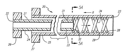
FIG. 5 is a schematic view of the catheter-delivery
system of the invention wherein the self-expanding stmt is
positioned within the inner lumen of the outer member before
the stent is mounted on the inner member.
FIG. 5A is a section on the line 5A - 5A of FIG.5.
FIG. 6 is a schematic view depicting the inner member
positioned within the inner lumen of the self-expanding stmt,
and a tapered mandrill inserted in the inner member for the
purpose of applying heat to form attachment projections.
FIG. 7 is a schematic view depicting an alternative
embodiment of the invention in which an elastomeric segment is
positioned on the distal end of the inner member and is used to
conform and fill in the open lattice structure of the self-
expanding stmt with attachment projections.
FIG. 8 is a schematic view of an over-the-wire
catheter-delivery system in which the stmt is being positioned
at a narrowed portion of the vessel wall.
FIG. 9 is a schematic view depicting the over-the-
wire catheter-delivery system of FIG. 8 in which the outer
21~~~3~
-6-
member is being withdrawn proximally so that the stmt can
self-expand radially outwardly into contact with the vessel
wall.
FIG. 10 is a schematic view depicting the stmt of
FIGS. 8 and 9 being implanted and contacting the vessel wall.
FIG. 11 is a schematic view depicting a rapid
exchange catheter-delivery system in which the guide wire
extends through a port in the side of catheter so that the
catheter rapidly may be exchanged upon withdrawal from the
patient.
FIG. 12 is a schematic view depicting the catheter-
delivery system of FIG. 11 in which the stmt self-expands as
the outer member is withdrawn axially in the proximal
direction.
FIG. 13 is a schematic view depicting the rapid-
exchange catheter-delivery system in which the self-expanding
stmt has been implanted and brought into contact with the
vessel wall, and the rapid-exchange catheter is ready to be
withdrawn from the vascular system of the patient.
DETAILED DESCRIPTION OF THE PREFERRED EMBODIMENTS
The present invention relates to a stmt catheter-
delivery system in which a self-expanding stmt is delivered
intraluminally into the body lumen of a human patient, such as
a coronary artery, carotid artery, one of the renal arteries,
or the peripheral arteries or veins, and the like. The
invention provides for a stmt catheter-delivery assembly and
a method of its use during which a stmt is implanted in a
patient.
As can be seen in FIGS . 1-4 , there are numerous prior
art stem s which are adapted for use with the present
invention. The stems 10 depicted in FIGS. 1-4 are all self-
~19~J~~
_7_
expanding stents and will expand from a contracted condition,
i.e., the condition in which the stents are mounted on the
catheter assembly, to an expanded condition in which the stmt
is caused to come into contact with the body lumen. The stems
are self-expanding, which can be achieved by several means. As
depicted in FIGS. 1-4, the prior art stems 10 are formed from
a stainless steel material and are configured so as to be
biased radially outwardly, intended to expand when any
restraints discouraging expansion are removed. The stems
depicted in FIGS. 1-4 also can be formed from a heat-sensitive
material, such as nickel-titanium, which material upon
application of a transformation temperature will self-expand
radially outwardly. These prior art stems are representative
of a large number of stems which can be adapted for use with
the present invention.
In a preferred embodiment of the invention, such as
is illustrated in FIGS. 5-6, the catheter assembly 20 is
provided to deliver and implant a stent . The catheter assembly
incorporates an elongated catheter body 21 which has a
20 proximal end 22 and a distal end 23. The inner member 24 and
an outer member 25 are arranged in coaxial alignment. The
inner member 24 is slidably positioned within the outer member
and relative axial movement between the two members is made
possible by an inner member control handle 26 and an outer
25 member control handle 27. The control handles 26,27 can take
numerous forms, but are depicted schematically for ease of
illustration. As an example, however, the control handles
26,27 can take the form of a thumb-switch arrangement, a
rotating-screw-type arrangement, or a ratcheting arrangement.
Such control handle means are well known in prior art catheter-
delivery systems.
A self-expanding stmt 28 having an open lattice
structure 29 is mounted on the distal end 23 of the catheter
assembly 20. The self-expanding stmt 28 virtually can take
any configuration that has an open lattice structure 29, as can
be seen in the examples of the prior art stems shown in FIGS.
1-4.
-- 219853
_8_
In keeping with the invention, the self-expanding
stmt 28 is inserted in the inner lumen 31 of the outer member
25, and positioned at the distal end 23 of the outer member.
In those applications in which the self-expanding stmt 28 is
made from stainless steel or a similar material that is biased
outwardly, the stmt 28 will be compressed and inserted into
the inner lumen 31 prior to delivery to the site of deployment .
Thereafter, the distal end 32 of the inner member 24 is
positioned within the stent inner lumen 34 so that the outer
surface 33 of the inner member 24 can come into contact with
the stmt inner lumen 34.
In keeping with the preferred embodiment, the distal
end 32 of inner member 24 is made from a polymeric material
that either is soft by design, or that will become soft when
heat is applied. The intent is to removably attach the self-
expanding stmt 28 on the outer surface 33 of inner member 24
of the inner member 24 of the elongated catheter body. The
outer surface 33 of inner member 24 partially will fill the
open lattice structure 29 of the stmt 28 to form attachment
projections 30 so that the stmt cannot move in an axial
direction along the outer surface 33 of the inner member 24.
In the preferred embodiment, the self-expanding stmt
28 is mounted on the outer surface 33 at the distal end 32 of
inner member 24 and the open lattice structure 29 is filled by
attachment projections 30. Due to the coaxial arrangement
between the inner member 24 and the outer member 25, the inner
lumen 31 of the outer member 25 covers self-expanding stmt 28
and assists in retaining the stmt on the outer surface 33 of
the inner member 24.
In order to conform the outer surface 33 so that it
conforms or fills the open lattice structure 29 of the self-
expanding stmt with attachment projections 30, heat can be
applied by various methods. For example, a tapered mandrel 35,
as shown in FIG. 6, can be inserted in the distal end 32 of the
inner member 24 in the region of the stent. Heat is then
applied to the outer member 25 by means well known to those
skilled in the relevant art, such as by using a heated-capture
219853
-9-
tube (not shown) surrounding the outer member 25. The capture
tube can be formed from the material manufactured under the
tradename "TEFLON" by the E.I. duPont de Nemours, Co., glass,
or the like and generally is warmed by using heated air. As
the outer member 25 is warmed, inner member 24 is inserted
within the inner lumen 31 of the outer member 25, thus allowing
attachment projections 30 to flow and to form around the stmt
28.
In another preferred embodiment, as depicted in FIG.
7, an elastomeric segment 40 is attached on the outer surface
33 of inner member 24 of elongated catheter body 21 at the
distal end 32 of the inner member 24. The elastomeric segment
40 is formed from a heat-sensitive material, or is designed to
be relatively soft as compared to the inner member 24, such
that the stmt 28 can be removably attached on the elastomeric
segment 40, which segment will conform and fill in the open
lattice structure 29 of the stmt with attachment projections
30. The elastomeric segment can be heated by the afore-
mentioned methods or, if it is formed of a material that is
relatively soft, it naturally will conform and fill in the open
lattice structure 29 with attachment projections 30 without the
application of heat.
In the preferred method of use, the catheter assembly
20 is used to implant the self-expanding stmt in a body lumen
using an over-the-wire or rapid-exchange catheter
configuration. In one preferred embodiment, as depicted in
FIGS. 8-10, the over-the-wire catheter 50 has a guide wire
lumen 51 which extends through the catheter and that is
configured to receive the guide wire 52. In order to implant
the self-expanding stmt 28, the guide wire 52 is positioned in
the body lumen of a patient, at a point along vessel wall 55,
and typically the guide wire 52 extends past a stenosed region
56. The distal end 54 of the over-the-wire catheter 50 is
threaded over the proximal end of the guide wire which is
outside the patient (not shown) and the catheter 50 is advanced
along the guide wire until the distal end 54 of the catheter 50
is positioned within the stenosed region 56.
~1985~0
-10-
As depicted in FIGS. 9 and 10, the self-expanding
stmt 28 is implanted in the stenosed region 56 by moving the
outer member 25 of the elongated catheter body 21 in a proximal
direction while simultaneously moving the inner member 24 in a
distal direction. The stmt 28 will not slide or move axially
on the outer surface 33 because the open lattice structure 29
is filled in with attachment projections 30. As portions of
the self-expanding stmt 28 are no longer contained by the
outer member 25, it will expand radially outwardly into contact
with the vessel wall 55 in the area of the stenosed region 56.
When fully deployed and implanted, as shown in FIG. 10, the
stent 28 will support and will hold open the stenosed region 56
so that fluid flow is not restricted. Attachment projections
30 do not inhibit the stmt 28 from self-expanding radially
outwardly, but rather attachment projections 30 only impede
axial movement of the stent.
With certain self-expanding stems, there is a
tendency of the stmt to shorten somewhat upon expansion. When
stent shortening occurs, the clinician may find that the stmt
has been placed improperly in the stenosed region 56, if the
effects of shortening previously have not been taken into
consideration. Accordingly, it may be necessary, as described
above, to move the inner member 24 distally in order to
compensate for stmt shortening upon expansion of the stent.
It also is possible, due to stmt design, for the self-
expanding stmt to not appreciably shorten upon expansion. If
this is the case, it may be unnecessary to move the inner
member 24 distally while simultaneously moving the outer member
25 proximally in order to release the self-expanding stmt 28
in the body lumen. With a stmt configuration that does not
appreciably shorten during expansion, the outer member 25 is
moved axially while the inner member 24 remains stationary as
the self-expanding stmt 28 expands radially outwardly into
contact with the vessel wall 55. After the stmt 28 is
implanted and contacts the stenosed region 56, the over-the-
wire catheter 50 is withdrawn from the vascular system of the
219850
-11-
patient. A typical over-the-wire catheter design is disclosed
in U.S. Patent No. 4,323,071.
In another preferred method of implanting a stmt, as
is depicted in FIGS. 11-13, a rapid-exchange catheter 60 is
provided. Rapid-exchange catheters are known in the art and
details of the construction and use are set forth in U.S.
Patent Nos. 5,458,613; 5,346,505; and 5,300,085. Generally,
rapid-exchange catheters include a guide wire lumen 61 which
extends in the distal portion of the catheter from a side port
63 to the distal end of the catheter. The guide wire 62 is
inserted through the side port 63 and extends out of the distal
end of the catheter 60 so that the distal end of the guide wire
is positioned beyond the stenosed region 56. The method of
deploying the self-expanding stmt 28 using the rapid-exchange
catheter 60 is similar to that described for using the over-
the-wire catheter 50. One of the differences between the two
catheter-delivery systems includes a slit 64 in the rapid-
exchange catheter 60 which extends from the side port 63 to
approximately just proximal of the area where the stmt 28 is
mounted. After the stmt 28 is implanted in the stenosed
region 56, the rapid-exchange catheter 60 is withdrawn from the
vascular system of the patient and the guide wire 62 will peel
through the slit 64, making the exchange of one catheter for
another a simple process. Typically, a stiffening mandrel 65
is incorporated in the proximal region of the rapid-exchange
catheter 60 to enhance the pushability of the catheter through
the vascular system of the patient, and to improve the
trackability of the catheter vis a vis the guide wire.
The stems as described herein can be formed from any
number of materials, including metals, metal alloys and
polymeric materials. Most desirably, the stents are formed
from metal alloys such as stainless steel, tantalum, or the
metal alloys classed as heat-sensitive such as nickel-titanium
(NiTi). Stems formed from stainless steel or similar alloys
typically are designed, such as in a helical coil or the like,
so that the stems are spring-biased outwardly.
-12- 2198530
With respect to stems formed from shape-memory
alloys such as a nickel-titanium alloy (NiTi), the stmt will
remain passive in its martensitic state when it is kept at a
temperature below the transition temperature. In this case,
the transition temperature will be below normal body
temperatur, at or below 37° C (98.6° F). When the NiTi stmt
is exposed to normal body temperature, it immediately will
attempt to return to its austenitic state, and will rapidly
expand radially outwardly to achieve its preformed state.
Details relating to the properties of devices made from nickel-
titanium can be found in "Shape-Memory Alloys," Scientific
American, Vol. 281, pages 74-82 (Nov. 1979).
With respect to all of the embodiments disclosed
above, inner member 24, and for that matter outer member 25,
can be formed from polymeric materials including polyurethanes,
polyethylenes, polyethylterpthalate, and nylons. Similarly,
the elastomeric segment 40 can be formed from polyurethane,
elastomeric polyesters and the like. Generally speaking, the
more proximal portions of the inner member 24 and the outer
member 25 will be formed of a polymeric material that is
stiffer than the distal section so that the proximal section
has sufficient pushability to advance through the vascular
system of the patient. On the other hand, the more distal
portions of the inner member 24 and the outer member 25 can be
formed of a more flexible material so that the distal portion
of the catheter will remain flexible and will track more easily
over the guide wire.
Other modifications and improvements may be made
without departing from the scope of the invention. For
example, the various drawing figures depict several
configurations of the stmt including various sizes, which can
be modified to suit a particular application without departing
from the spirit and scope of the invention. Further, the
conf iguration of the catheter assembly is a coaxial arrangement
between the inner member and the outer member, which can be
modified to other configurations without departing from the
preferred invention.