Sélection de la langue

Search

Sommaire du brevet 2202823 

Énoncé de désistement de responsabilité concernant l'information provenant de tiers

Une partie des informations de ce site Web a été fournie par des sources externes. Le gouvernement du Canada n'assume aucune responsabilité concernant la précision, l'actualité ou la fiabilité des informations fournies par les sources externes. Les utilisateurs qui désirent employer cette information devraient consulter directement la source des informations. Le contenu fourni par les sources externes n'est pas assujetti aux exigences sur les langues officielles, la protection des renseignements personnels et l'accessibilité.

Disponibilité de l'Abrégé et des Revendications

L'apparition de différences dans le texte et l'image des Revendications et de l'Abrégé dépend du moment auquel le document est publié. Les textes des Revendications et de l'Abrégé sont affichés :

  • lorsque la demande peut être examinée par le public;
  • lorsque le brevet est émis (délivrance).
(12) Demande de brevet: (11) CA 2202823
(54) Titre français: DISPOSITIF DE MISE A PLAT D'UN TUBE PELLICULAIRE
(54) Titre anglais: DEVICE FOR FLATTENING A FILM TUBE
Statut: Réputée abandonnée et au-delà du délai pour le rétablissement - en attente de la réponse à l’avis de communication rejetée
Données bibliographiques
(51) Classification internationale des brevets (CIB):
  • B29C 55/28 (2006.01)
  • B29C 49/28 (2006.01)
  • B29C 53/10 (2006.01)
(72) Inventeurs :
  • VOSS, KLAUS-PETER (Allemagne)
  • SENSEN, KLEMENS (Allemagne)
  • DELLBRUGGE, HERBERT (Allemagne)
  • SCHIBALLA, SIEGFRIED (Allemagne)
(73) Titulaires :
  • WINDMOLLER & HOLSCHER
(71) Demandeurs :
  • WINDMOLLER & HOLSCHER (Allemagne)
(74) Agent: AVENTUM IP LAW LLP
(74) Co-agent:
(45) Délivré:
(22) Date de dépôt: 1997-04-16
(41) Mise à la disponibilité du public: 1997-11-03
Requête d'examen: 2002-04-16
Licence disponible: S.O.
Cédé au domaine public: S.O.
(25) Langue des documents déposés: Anglais

Traité de coopération en matière de brevets (PCT): Non

(30) Données de priorité de la demande:
Numéro de la demande Pays / territoire Date
196 17 811.8 (Allemagne) 1996-05-03

Abrégés

Abrégé français

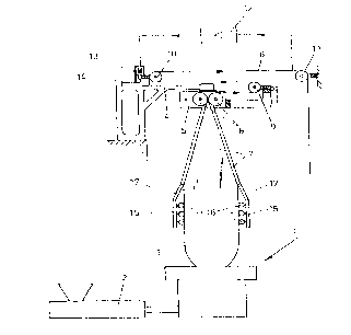
Dispositif de mise à plat d'un tube pelliculaire tiré d'une bulle pelliculaire gonflée produite par la tête d'extrusion-soufflage d'un système de soufflage de feuilles minces constitué de panneaux de mise à plat délimitant la bulle pelliculaire et placés contre elle en forme de V en face des rouleaux pinceurs d'un poste de tirage et d'enroulement, d'un châssis tournant entraîné qui retient les panneaux de mise à plat, supporte les rouleaux pinceurs et supporte les barres de détour et, au besoin, un rouleau tendeur autour de son axe de rotation en mode pivotant, et d'un dispositif de calibrage placé entre la tête d'extrusion-soufflage et les panneaux de mise à plat. Dans le but de prévenir les perturbations et la formation de plis en bordure causés par la torsion de la bulle au moment où le tube pelliculaire est mis à plat, le dispositif de calibrage est entraîné en mode rotatif, toujours dans le même sens de rotation que les panneaux de mise à plat.


Abrégé anglais


A device for flattening a film tube taken up from an
inflated film bubble extruded from the film-blowing head of a
film-blowing system consisting of flattening platens delimiting
the film bubble and placed against it in the form of a wedge,
which are positioned in front of the squeeze rollers of a film
take-up and winding device, of a driven reversing frame which
holds the flattening platens, supports the squeeze rollers and
supports the turning bars and, if necessary, an idle roller
about its axis of rotation in pivoting fashion, and of a
calibrating device arranged between the film-blowing head and
flattening platens. In order to prevent disturbances and the
formation of edge folds caused by the twisting of the film
bubble as the film tube is flattened, the calibrating device
is driven in a rotating fashion, in all cases, in the same
direction of rotation as the flattening platens.

Revendications

Note : Les revendications sont présentées dans la langue officielle dans laquelle elles ont été soumises.


The embodiments of the invention in which an exclusive property
or privilege is claimed are defined as follows:
1. An apparatus for flattening a film tube taken up from
an inflated film bubble extruded from the film-blowing head of
a film-blowing system consisting of:
flattening platens delimiting the film bubble and placed
against the film bubble in the form of a wedge, which are
positioned in front of the squeeze rollers of a film take-up
and winding device;
a driven reversing frame which holds the flattening
platens, supports the squeeze rollers and supports turning bars
and which rotates about the axis of rotation of the frame in
a pivoting fashion; and
a calibrating device arranged between the film-blowing
head and the flattening platens;
wherein the calibrating device is driven in a rotating
fashion with, in all cases, a direction of rotation identical
to that of the flattening platens.
2. An apparatus according to Claim 1, wherein the
calibrating device is connected to the flattening platens.
3. An apparatus according to Claim 1 or 2, wherein the
calibrating device is driven by means of a rotary ring that is
connected to the film-blowing head and is driven by means of
a servo.
4. An apparatus according to Claim 3, wherein the
calibrating device is driven at a slower speed of rotation than
the flattening platens.
5. An apparatus according to Claim 1, 2 or 3 wherein the
driven reversing frame also an idle roller.

Description

Note : Les descriptions sont présentées dans la langue officielle dans laquelle elles ont été soumises.


CA 02202823 1997-04-16
1222-19
DEVICE FOR FLA~ NlNG A FILM TUBE
The invention relates to a device for flattening a film
tube drawn off from an inflated film bubble extruded from the
film-blowing head of a film-blowing system, consisting of
flattening platens delimiting the film bubble and placed
against it in the form of a wedge, which precede the squeeze
rollers of a film take-up and winding device, of a driven
reversing frame which holds the flattening platens, the squeeze
rollers and supports turning bars and, if necessary, idle
rollers about its axis of rotation in pivoting fashion, and of
a calibrating device arranged between the film-blowing head and
flattening platens.
Film-blowing systems having flattening platens that are
reversible up to 360~ and having idle rollers and turning bars
of this type are known, e.g., from DE-OS 2,035,584, 4,303,952,
DE-PS 2,156,079, 3,506,772 and EP 0,292,614 A2. A calibrating
device, commonly in the form of a so-called calibrating cage,
is positioned in front of the reversing flattening platens and
supports the film bubble in the vicinity of, and above, the
so-called frost line.
In order to enable an improved sliding of the film tube
as it is flattened over the flattening platens, the latter can
be provided with strips having low-friction surfaces or with
low-friction coatings or else provided with rollers or small
rollers. In spite of a low-friction guiding on flattening
platens of a film tube to be flattened, problems may arise when
flattening the film tube if its not fully cooled surface is
sticky. More specifically, difficulties arise during the
flattening process when a reversing take-up is provided, thus,
the flattening platens with squeeze rollers downstream are
driven to be reversible by angles of up to 360~. For a
reversing take-up, when flattening highly adhesive or sticky

CA 02202823 1997-04-16
film tubes, an undesirable formation of edge folds occurs in
the upper region of the flattening platens, which results from
a twisting of the film tube during the reversing turning
movement. For a nonadhering film with good sliding properties,
this twisting can be compensated for by means of a transversely
oriented sliding movement of the film with respect to the
flattening platens. However, for a highly adhesive and sticky
film, this compensation is no longer possible since the film
adheres too markedly to the flattening platens or to the
sliding elements, rollers or small rollers arranged thereon,
such that an undesirable formation of edge folds develops prior
to the squeeze rollers.
The purpose of the invention is to create an apparatus for
flattening a film tube drawn off from an inflated film bubble
extruded from the film-blowing head of a film-blowing system,
in which disturbances and formations of edge folds caused by
an uncompensated twisting of the film tube are avoided in the
region of the flattening platens.
In accordance with the invention, there is provided an
apparatus for flattening a film tube drawn off from an inflated
film bubble extruded from the film-blowing head of a
film-blowing system, in which the calibrating device is driven
in a rotating fashion with, in all cases, a direction of
rotation precisely identical to that of the flattening platens.
In the apparatus in accordance with the invention, the
calibrating device rotates in the same direction as the
flattening platens. Since the calibrating device consists of
rings laterally supporting the film bubble, or of annular
segments that are provided with low-friction coverings or small
rollers, these engage the section of the film bubble which they
support. Due to their reversing rotational movement, that the
twisting of the film tube caused by means of the reversing is
displaced to a region underneath the flattening platens, in

CA 02202823 1997-04-16
which the film bubble is still plastic, so that the twisting
is compensated for by means of a plastic deformation of the
film bubble. Distortion of the film tube as it is being
flattened in the region of the flattening platens, which cause
the formation of edge folds and disturbances, are thereby
avoided. In accordance with the invention, the twist generated
by means of the reversing is displaced far into the plastic
region of the film bubble, where it can be compensated for
without disturbance by twisting the still plastic film bubble.
The calibrating device may be connected directly to the
flattening platens so that it reverses together with the
flattening platens.
In accordance with another embodiment, it is provided that
the calibrating device is connected to the film-blowing head
by means of a rotary ring and is driven by means of a servo.
In this arrangement, the calibrating device may be driven at
a lower rotational speed than the flattening platens, such that
the extent of twisting can be adapted to the more limited
height of the calibrating device in comparison to the
flattening platens and take-up rollers.
Embodiments of the invention are explained in greater
detail below with the aid of the drawings, in which:
Figure 1 shows a schematic lateral view of a first
embodiment in which the calibrating cage is connected directly
to the flattening platens, and
Figure 2 shows a schematic lateral view of a second
embodiment in which the calibrating cage is supported on the
film-blowing head by means of a rotary ring and is driven by
means of a separate drive.
A conventional film-blowing head 1 as shown in Figure 1
is fed by an extruder 2 with a molten plastic. A film tube,
which is inflated to a film bubble 3 in a conventional fashion

CA 02202823 1997-04-16
by means of supporting and cooling air emerges vertically from
the annular gap of the film-blowing head 1. The supporting and
cooling air is supplied and carried away by means of lines, not
shown, that pass through the film-blowing head.
Above the film-blowing head 1, there is a stationary
gallows-shaped carrier 4, which supports both the rotatable
take-up and squeeze rollers 6 and the flattening platens 7.
The carrier 4 also supports a frame 5, so that it can rotate
about a vertical axis. The frame 5 is driven to be reversible
by up to 360~ by means of a suitable conventional drive, not
shown. The laid-flat film tube 8, taken up from the film bubble
3, passes over the turning bars 9,10 and the idle roller 11,
rigidly supported on the frame, to a conventional take-up
device, not shown. A measuring device that consists of two
edge detectors is arranged in the region between the turning
bar 10 and the idle roller 11. When the edge detectors detect
a mismatch of the edges of the film tube that is being taken
up, they generate measuring signals that are supplied to a
control circuit 12. The control circuit 12 generates control
signals, as a linear function of the measuring signals, which
are supplied to a motor 13 arranged on the gallows-shaped
carrier 4 and with the operation of which the U-shaped frame
14, and consequently the turning bar 10, pivots about its
vertical shaft. This form of take-up and lay-flat device for
film tubes produced in a blowing process by an extruder having
a film-blowing head is described in EP 0,292,614 A2, to which
reference is made for a more detailed description.
The embodiment of the invention in accordance with Figure
1 differs from the device shown in EP 0,292,614 A2 due to the
fact that the calibrating cage 15, with its calibrating rings
or annular segments 16 held therein, is connected directly to
the flattening platens 7 by means of carrying pieces 17 so that
the calibrating cage 15 reverses with the flattening platens

CA 02202823 1997-04-16
7 in the same direction of rotation and at identical angles of
rotation.
In Figure 2, a film-blowing system is shown which has a
take-up device for the film tube produced from the extruder
with film-blowing head in the blowing process, which, in
principle, is of an identical construction to that shown and
discussed above with reference to Figure 1. However, the
apparatus shown in Figure 2 differs from that shown in Figure
1 in that the calibrating cage 15 with its support rings or
annular support segments 16 is not attached to the flattening
platens 7. Instead, it is attached by the carrier 18 to a
rotary ring 19 having external toothing. The ring 19 is
supported in a rotating fashion on a carrier ring 20 connected
to the film-blowing head. A servo motor 21, the rotational
speed and direction of rotation of which are controlled, is
flange-mounted on the carrier ring 20. The output gear of the
servo motor 22 meshes with the outer toothing of the rotary
ring 19. The rotary ring 19 is arranged concentrically to the
center line of the extruded film tube. The servo motor 21 is
controlled by means of a control device, not shown, such that
the calibrating cage 15 reverses in the same direction of
rotation as the flattening platens and at an angle of rotation
that is adapted to the location of the calibrating cage 15
between the film-blowing head 1 and flattening platens 7.

Dessin représentatif
Une figure unique qui représente un dessin illustrant l'invention.
États administratifs

2024-08-01 : Dans le cadre de la transition vers les Brevets de nouvelle génération (BNG), la base de données sur les brevets canadiens (BDBC) contient désormais un Historique d'événement plus détaillé, qui reproduit le Journal des événements de notre nouvelle solution interne.

Veuillez noter que les événements débutant par « Inactive : » se réfèrent à des événements qui ne sont plus utilisés dans notre nouvelle solution interne.

Pour une meilleure compréhension de l'état de la demande ou brevet qui figure sur cette page, la rubrique Mise en garde , et les descriptions de Brevet , Historique d'événement , Taxes périodiques et Historique des paiements devraient être consultées.

Historique d'événement

Description Date
Inactive : CIB expirée 2019-01-01
Inactive : Demande ad hoc documentée 2018-06-06
Exigences relatives à la révocation de la nomination d'un agent - jugée conforme 2018-05-18
Exigences relatives à la nomination d'un agent - jugée conforme 2018-05-18
Le délai pour l'annulation est expiré 2006-04-18
Demande non rétablie avant l'échéance 2006-04-18
Inactive : CIB de MCD 2006-03-12
Réputée abandonnée - omission de répondre à un avis sur les taxes pour le maintien en état 2005-04-18
Modification reçue - modification volontaire 2005-03-04
Inactive : Dem. de l'examinateur art.29 Règles 2004-09-07
Inactive : Dem. de l'examinateur par.30(2) Règles 2004-09-07
Lettre envoyée 2002-05-29
Requête d'examen reçue 2002-04-16
Toutes les exigences pour l'examen - jugée conforme 2002-04-16
Exigences pour une requête d'examen - jugée conforme 2002-04-16
Lettre envoyée 1999-09-28
Inactive : Transfert individuel 1999-09-09
Demande publiée (accessible au public) 1997-11-03
Inactive : Certificat de dépôt - Sans RE (Anglais) 1997-09-23
Inactive : Correction au certificat de dépôt 1997-08-20
Inactive : CIB attribuée 1997-08-06
Inactive : CIB en 1re position 1997-08-06
Inactive : Certificat de dépôt - Sans RE (Anglais) 1997-07-16
Inactive : Inventeur supprimé 1997-07-07
Inactive : Demandeur supprimé 1997-07-07
Inactive : Inventeur supprimé 1997-07-07

Historique d'abandonnement

Date d'abandonnement Raison Date de rétablissement
2005-04-18

Taxes périodiques

Le dernier paiement a été reçu le 2004-04-16

Avis : Si le paiement en totalité n'a pas été reçu au plus tard à la date indiquée, une taxe supplémentaire peut être imposée, soit une des taxes suivantes :

  • taxe de rétablissement ;
  • taxe pour paiement en souffrance ; ou
  • taxe additionnelle pour le renversement d'une péremption réputée.

Les taxes sur les brevets sont ajustées au 1er janvier de chaque année. Les montants ci-dessus sont les montants actuels s'ils sont reçus au plus tard le 31 décembre de l'année en cours.
Veuillez vous référer à la page web des taxes sur les brevets de l'OPIC pour voir tous les montants actuels des taxes.

Historique des taxes

Type de taxes Anniversaire Échéance Date payée
Taxe pour le dépôt - générale 1997-04-16
TM (demande, 2e anniv.) - générale 02 1999-04-16 1999-04-15
Enregistrement d'un document 1999-09-09
TM (demande, 3e anniv.) - générale 03 2000-04-17 2000-03-20
TM (demande, 4e anniv.) - générale 04 2001-04-17 2001-04-10
Requête d'examen - générale 2002-04-16
TM (demande, 5e anniv.) - générale 05 2002-04-16 2002-04-16
TM (demande, 6e anniv.) - générale 06 2003-04-16 2003-04-16
TM (demande, 7e anniv.) - générale 07 2004-04-16 2004-04-16
Titulaires au dossier

Les titulaires actuels et antérieures au dossier sont affichés en ordre alphabétique.

Titulaires actuels au dossier
WINDMOLLER & HOLSCHER
Titulaires antérieures au dossier
HERBERT DELLBRUGGE
KLAUS-PETER VOSS
KLEMENS SENSEN
SIEGFRIED SCHIBALLA
Les propriétaires antérieurs qui ne figurent pas dans la liste des « Propriétaires au dossier » apparaîtront dans d'autres documents au dossier.
Documents

Pour visionner les fichiers sélectionnés, entrer le code reCAPTCHA :


Pour visualiser une image, cliquer sur un lien dans la colonne description du document. Pour télécharger l'image (les images), cliquer l'une ou plusieurs cases à cocher dans la première colonne et ensuite cliquer sur le bouton "Télécharger sélection en format PDF (archive Zip)" ou le bouton "Télécharger sélection (en un fichier PDF fusionné)".

Liste des documents de brevet publiés et non publiés sur la BDBC .

Si vous avez des difficultés à accéder au contenu, veuillez communiquer avec le Centre de services à la clientèle au 1-866-997-1936, ou envoyer un courriel au Centre de service à la clientèle de l'OPIC.


Description du
Document 
Date
(aaaa-mm-jj) 
Nombre de pages   Taille de l'image (Ko) 
Dessin représentatif 1997-12-03 1 7
Abrégé 1997-04-15 1 24
Description 1997-04-15 5 227
Dessins 1997-04-15 2 27
Revendications 1997-04-15 1 37
Revendications 2005-03-03 6 250
Revendications 2005-03-03 1 38
Certificat de dépôt (anglais) 1997-07-15 1 165
Certificat de dépôt (anglais) 1997-09-22 1 165
Rappel de taxe de maintien due 1998-12-16 1 110
Courtoisie - Certificat d'enregistrement (document(s) connexe(s)) 1999-09-27 1 140
Rappel - requête d'examen 2001-12-17 1 118
Accusé de réception de la requête d'examen 2002-05-28 1 179
Courtoisie - Lettre d'abandon (taxe de maintien en état) 2005-06-12 1 175
Correspondance 1997-08-19 2 64
Taxes 2002-04-15 1 36
Taxes 2000-03-19 1 38
Taxes 2001-04-09 1 34
Taxes 1999-04-14 1 37