Sélection de la langue

Search

Sommaire du brevet 2207967 

Énoncé de désistement de responsabilité concernant l'information provenant de tiers

Une partie des informations de ce site Web a été fournie par des sources externes. Le gouvernement du Canada n'assume aucune responsabilité concernant la précision, l'actualité ou la fiabilité des informations fournies par les sources externes. Les utilisateurs qui désirent employer cette information devraient consulter directement la source des informations. Le contenu fourni par les sources externes n'est pas assujetti aux exigences sur les langues officielles, la protection des renseignements personnels et l'accessibilité.

Disponibilité de l'Abrégé et des Revendications

L'apparition de différences dans le texte et l'image des Revendications et de l'Abrégé dépend du moment auquel le document est publié. Les textes des Revendications et de l'Abrégé sont affichés :

  • lorsque la demande peut être examinée par le public;
  • lorsque le brevet est émis (délivrance).
(12) Brevet: (11) CA 2207967
(54) Titre français: CYLINDRE ENTRAINE
(54) Titre anglais: DRIVEN CYLINDER
Statut: Périmé et au-delà du délai pour l’annulation
Données bibliographiques
(51) Classification internationale des brevets (CIB):
  • B41F 03/54 (2006.01)
  • B41F 13/004 (2006.01)
(72) Inventeurs :
  • PETERSEN, GODBER (Allemagne)
  • GOTTLING, JOSEF (Allemagne)
  • FELLER, BERNHARD (Allemagne)
  • FLEISCHMANN, HANS (Allemagne)
(73) Titulaires :
  • MANROLAND AG
(71) Demandeurs :
  • MANROLAND AG (Allemagne)
(74) Agent: NORTON ROSE FULBRIGHT CANADA LLP/S.E.N.C.R.L., S.R.L.
(74) Co-agent:
(45) Délivré: 2000-06-06
(22) Date de dépôt: 1997-06-16
(41) Mise à la disponibilité du public: 1997-12-19
Requête d'examen: 1997-06-16
Licence disponible: S.O.
Cédé au domaine public: S.O.
(25) Langue des documents déposés: Anglais

Traité de coopération en matière de brevets (PCT): Non

(30) Données de priorité de la demande:
Numéro de la demande Pays / territoire Date
196 24 394.7 (Allemagne) 1996-06-19

Abrégés

Abrégé français

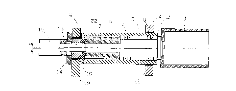
Dans l'entraînement compact d'un cylindre à montage flottant d'une presse rotative, le mandrin portant le cylindre est logé avec le moteur dans un tube porteur monté dans la paroi.


Abrégé anglais


In a compact drive for a float-mounted cylinder of a
rotary printing machine, the spindle carrying the cylinder
is housed together with a motor in a carrier tube mounted
in the side wall.

Revendications

Note : Les revendications sont présentées dans la langue officielle dans laquelle elles ont été soumises.


- 7 -
The embodiments of the invention in which an
exclusive property or privilege is claimed are defined as
follows:-
1. A driven cylinder of an aggregate of a rotary
printing machine with a side wall, in which the cylinder
is float mounted, comprising:
a spindle;
a cylinder body arranged on the spindle;
a rotatable carrier tube mounted in the side wall,
the spindle being mounted in the carrier tube; and
motor means for driving the cylinder body, the motor
means being arranged in the carrier tube and connected to
the spindle.
2. A driven cylinder as defined in claim 1, wherein the
cylinder body is pot-shaped with a bottom, the spindle
having a spindle head attached to an outer surface of the
cylinder body bottom.
3. A driven cylinder as defined in claim 1, wherein the
cylinder body is configured to have a bottom approximately
at a mid-point along a longitudinal axis of the cylinder,
the spindle having a head connected to the bottom of the
cylinder body.
4. A driven cylinder as defined in claim 1, 2 or 3,
wherein the carrier tube is rotatable mounted in the side
wall, the spindle being mounted in the side wall
eccentrically relative to a rotational axis of the carrier
tube, and further comprising adjustment means for rotating
the carrier tube.
5. A driven cylinder as defined in claim 1, 2 or 3,
wherein the carrier tube is mounted in the side wall in an
axially movable manner, and further comprising adjustment
means for axially moving the carrier tube.

- 8 -
6. A driven cylinder as defined in claim 1, 2, 3, 4 or
5, wherein said driven cylinder is a form cylinder.
7. A driven cylinder as defined in claim 1, 2, 3 or 4,
wherein said driven cylinder is a transfer cylinder.
8. A driven cylinder as defined in claim 1, 2 or 3,
wherein said driven cylinder is a web transport roller.
9. A driven cylinder as defined in claim 1, 2 or 3,
wherein said driven cylinder is a folding unit cylinder.

Description

Note : Les descriptions sont présentées dans la langue officielle dans laquelle elles ont été soumises.


CA 02207967 1997-06-16
-- 1 --
DRIV13N C ~.Tl~lh~
P~K~OUN~ OF THE INVENTION
The invention relates to a driven cylinder of an
aggregate of a rotary printing machine.
Description of the Prior Art
German application DE 195 15 459.2 discusses a rubber
blanket cylinder that is float-mounted in the side wall of
a printing unit. The rubber blanket cylinder is attached
to a spindle, which is mounted in a housing, which in turn
is held in two walls. The spindle is driven by a drive to
which it is connected or by toothed gears. Drives of this
type are large and technically complicated. In some
cases, oil lubrication is needed. Because of the
elasticity of the drive, rotary play occurs at the driven
cylinder. In toothed-gear drives, the torsion becomes
even greater due to the backlash.
SUMMARY OF THE INVENTION
Accordingly, it is an object of the present invention
to provide a play-free, compact drive for cylinders.
The direct attachment of the motor to the
spindle carrying the cylinder guarantees a stable and
play-free drive. Spindle units of this type are compact
and have few individual parts, and thus can be
economically built. Furthermore, no external lubrication
is necessary. This cylinder type is advantageous, for
example, in so-called single wall machines for small press
runs. Form cylinders of this type are well-suited for the
production of printing forms in the printing machine using
what is known as "computer-to-press technology."
Furthermore, the individual drive of cylinders of this
type makes it possible to carry out set-up procedures
simultaneously. For example, while a printing form is
being produced on a form cylinder, an adjacent transfer
cylinder can be separately driven for a washing procedure.

CA 02207967 1997-06-16
-- 2
The various features of novelty which characterize
the invention are pointed out with particularity in the
claims annexed to and forming a part of the disclosure.
For a better understanding of the invention, its operating
advantages, and specific objects attained by its use,
reference should be had to the drawing and descriptive
matter in which there are illustrated and described
preferred embodiments of the invention.
BRIBF ~R~RTPTION OF THE DRAWINGS
In the drawings:
Figure 1 is a longitudinal section of a cylinder,
including spindle unit, pursuant to the
present invention;
Figure 2 iS a view similar to Figure 1, of a further
embodiment;
Figure 3 is a section of an offset printing group
with float-mounted cylinders, along the
line III-III in Figure 4i
Figure 4 is a view IV in Figure 3; and
Figure 5 is a view V in Figure 3.
DET~TT.Rn DESCRIPTION OF THE ~Kr~rNTLY ~Krr~KK~v
EMBODIMBNTS
Figure 1 shows the float mounting of a cylinder 1,
which can be, for example, the form cylinder or transfer
cylinder of a printing group. The cylinder 1 is pot-
shaped, and its bottom is attached to the spindle head 2
of a spindle 3. Advantageously, this attachment is
carried out using screws, and the cylinder 1 is held
without play by means of a ball socket. The spindle 3 is
mounted in a carrier tube with high axial and radial
rigidity by roller bearings 4, 5. A motor 7
(advantageously, a so-called "kit" motor), that is also
supported in the carriér tube 6, is located on an extended
journal of the spindle 3, which is also supported by a
bearing 32. This arrangement ensures a rigid, play-free

CA 02207967 1997-06-16
connection of the motor 7 to the cylinder 1. The carrier
tube 6 is mounted in slide bearings 8, 9 in a side wall 11
and in a support wall 12. In the illustrated embodiment,
the carrier tube 6 is sealed by a sleeve 10, which is held
in the slide bearing 9. The second bearing, which is
located in the supporting wall 12, provides the carrier
tube 6 with especially stable support. The second bearing
can be designed, for example, as a plate screwed onto the
side wall 11 with spacing supports or as a bridge screwed
onto the side wall 11. The carrier tube 6 can be rotated
in the slide bearings 8, 9, which makes it possible for
the positioning movements of the cylinder 1 described
below to be carried out. To this end, the spindle 3,
along with the cylinder 1, is eccentric to the rotational
axis of the carrier tube 6. In the illustrated embodiment,
the bore in the carrier tube 6 in which the spindle 3 is
mounted is eccentric to the outer tube diameter, which
carries the bearing seat for accommodation in the slide
bearing 8. Similarly, the seat for the bearing 32 in the
sleeve 10 is eccentric to the bearing seat for the slide
bearing 9.
A rotary encoder 13 required for the purpose of drive
control is attached to the spindle 3 and supported by a
lever 14, which in turn is attached to the sleeve 10. The
spindle 3 is sealed by a two-way feed 15, via which a
liquid medium for printing process controls, e.g., a
cooling device, can be fed into and out of the cylinder 1.
Figure 2 shows a cylinder 16 with a spindle unit that
is wider in design and can therefore work with webs of
greater width. The cylinder 16, for example, a transfer
cylinder, is double pot-shaped, i.e., it has a bottom
located approximately at its middle. The cylinder 16 is
attached by this bottom to the spindle head 18 of a
spindle 19. The spindle 19 is mounted by means of roller
bearings 20, 21 in a carrier tube 17, which also holds the
kit motor 22 that is attached to the spindle 19. The kit
motor 22 is supported in the carrier tube 17 by means of a

CA 02207967 1997-06-16
sleeve 23. The extended journal of the spindle 19 also
runs in a roller bearing 24. The carrier tube 17 is
mounted by means of slide bearings 25, 26 in side wall 27
and a support wall 28. The extended journal extends out of
the side wall 27 to approximately the middle of the
cylinder 16. As a result, the spindle 19 is held in a
highly stable fashion in this area. Furthermore, the
central arrangement of the bottom, by which the cylinder
16 is attached to the spindle head 18, is advantageous for
low-bend operation of the cylinder 16. Its load is thus
distributed evenly on both two sides of the bottom.
As Figure 2 also shows, a rotary encoder 29 attached
to the spindle 19 is supported on a lever 30, which in
turn is attached to the sleeve 23. Again, there is a two-
way feed 31, via which the media for printing process
control can be fed into and out of the cylinder 16. The
cylinder 16 is eccentric relative to the pivot axis of the
carrier tube 17.
Figure 2 also shows an alternative way to arrange a
rotary encoder. A so-called spur gear rotary encoder 77
is located in the vicinity of the spindle head 18 at the
end of the carrier tube 17. The toothing for the rotary
encoder 77 is worked into the external diameter of the
spindle head 18.
The float mounting is also suitable for other driven
cylinders of printing machines. For example, a web
transport roller or the cylinder of a folding unit can be
attached to the spindle head 2, 18.
In these cases, the eccentricity e can be omitted.
It is also possible to manufacture the cylinder and the
spindle from a single piece, for example, in the case of a
folding unit cylinder.
Figures 3 to 5 show an offset printing group with
float-mounted cylinders. The drawings depict a so-called
double printing group, in which two printing groups work
together on the blanket-to-blanket principle. Form
cylinders 93, 94 and blanket cylinders 95, 96 are mounted

-
CA 02207967 1997-06-16
with the eccentricity e on spindle units 97-100 (Figure
3). The spindle units 97-100 correspond in design to the
spindle units shown in Figure 2. The spindle units 97-100
are mounted by slide bearings 101, 102 in a side wall 103
and a supporting wall. The supporting wall consists of
plates 104-107, which are screwed tightly onto webs or
flanges 108-111 in the side wall 103. However, this
detail is not the subject matter of the invention and will
therefore not be described further.
By means of adjustment units 112-115, the spindle
units 97-100 can be turned, as indicated by the double
arrows 120-123. For this purpose, levers 116-119 are
located on the carrier tubes of the spindle units 97-100.
The adjustment units 112-115, which rest directly or
indirectly on the side wall 103 (Figure 4), act upon the
levers 116-119.
By pivoting the spindle units 97-100, it is possible,
thanks to the eccentricity e, to adjust the distances al
to a3 of the form and transfer cylinders 93-96 relative to
one another (Figure 5). The form cylinders 93, 94
transfer the printing image via the transfer cylinders 95,
96 onto both sides of a web 124. Doing so requires
maintaining an even linear force as well as a defined
pressure between the transfer cylinders 95, 96. This
pressure is influenced by the thickness of the web 124
that runs between the transfer cylinders 95, 96. The
distance a2 between the transfer cylinders 95, 96 must
thus be set in accordance with the thickness of the web
124. If a2 changes, this will influence al and a3 as
well. For this reason, to maintain flawless image
transfers from the form cylinders 93, 94 onto the transfer
cylinders 95, 96, the distances al and a3 of these
cylinders relative to one another must also be changed.
This is done by activating the adjustment units 112, 114.
Movement out of the printing position is also
implemented by means of the adjustment units 113, 115.
For this purpose, the spindle units 98, 99 are pivoted

CA 02207967 1997-06-16
into their extreme positions, whereby the distance a2
reaches its maximum. The web 124 is then released by the
transfer cylinders 95, 96.
The spindle units 98, 99 that carry the transfer
cylinders 95, 96 are axially fixed by axial bearings 127,
128, while the spindle units 97, 100 that carry the form
cylinders 93, 94 are movable in the axial direction, as
indicated by the double arrows 131, 132 (Figure 3). By
means of this movement, the lateral register can be set.
The movement is implemented by means of adjustment units
129, 130, which are supported on the side wall 103 and are
connected to the spindle units 97, 100 in articulated
fashion.
For the adjustment units 112-115 and 129 and 130,
hydraulic or pneumatic working cylinders can be used, for
example, as can electric or electric-mechanical cylinders.
As in the embodiment in Figure 1, rotary
encoders 185-188 are attached to the spindle units 97-100
for drive control.
The invention is not limited by the embodiments
described above which are presented as examples only but
can be modified in various ways within the scope of
protection defined by the appended patent claims.

Dessin représentatif
Une figure unique qui représente un dessin illustrant l'invention.
États administratifs

2024-08-01 : Dans le cadre de la transition vers les Brevets de nouvelle génération (BNG), la base de données sur les brevets canadiens (BDBC) contient désormais un Historique d'événement plus détaillé, qui reproduit le Journal des événements de notre nouvelle solution interne.

Veuillez noter que les événements débutant par « Inactive : » se réfèrent à des événements qui ne sont plus utilisés dans notre nouvelle solution interne.

Pour une meilleure compréhension de l'état de la demande ou brevet qui figure sur cette page, la rubrique Mise en garde , et les descriptions de Brevet , Historique d'événement , Taxes périodiques et Historique des paiements devraient être consultées.

Historique d'événement

Description Date
Le délai pour l'annulation est expiré 2010-06-16
Lettre envoyée 2009-06-16
Lettre envoyée 2008-10-28
Inactive : CIB de MCD 2006-03-12
Accordé par délivrance 2000-06-06
Inactive : Page couverture publiée 2000-06-05
Préoctroi 2000-03-08
Inactive : Taxe finale reçue 2000-03-08
Un avis d'acceptation est envoyé 1999-10-14
Lettre envoyée 1999-10-14
Un avis d'acceptation est envoyé 1999-10-14
Inactive : Approuvée aux fins d'acceptation (AFA) 1999-09-15
Demande publiée (accessible au public) 1997-12-19
Lettre envoyée 1997-11-06
Inactive : CIB en 1re position 1997-09-11
Inactive : CIB attribuée 1997-09-11
Symbole de classement modifié 1997-09-08
Inactive : Transfert individuel 1997-09-05
Inactive : Lettre de courtoisie - Preuve 1997-08-26
Inactive : Certificat de dépôt - RE (Anglais) 1997-08-25
Inactive : Inventeur supprimé 1997-08-22
Demande reçue - nationale ordinaire 1997-08-22
Exigences pour une requête d'examen - jugée conforme 1997-06-16
Toutes les exigences pour l'examen - jugée conforme 1997-06-16

Historique d'abandonnement

Il n'y a pas d'historique d'abandonnement

Taxes périodiques

Le dernier paiement a été reçu le 2000-05-16

Avis : Si le paiement en totalité n'a pas été reçu au plus tard à la date indiquée, une taxe supplémentaire peut être imposée, soit une des taxes suivantes :

  • taxe de rétablissement ;
  • taxe pour paiement en souffrance ; ou
  • taxe additionnelle pour le renversement d'une péremption réputée.

Les taxes sur les brevets sont ajustées au 1er janvier de chaque année. Les montants ci-dessus sont les montants actuels s'ils sont reçus au plus tard le 31 décembre de l'année en cours.
Veuillez vous référer à la page web des taxes sur les brevets de l'OPIC pour voir tous les montants actuels des taxes.

Titulaires au dossier

Les titulaires actuels et antérieures au dossier sont affichés en ordre alphabétique.

Titulaires actuels au dossier
MANROLAND AG
Titulaires antérieures au dossier
BERNHARD FELLER
GODBER PETERSEN
HANS FLEISCHMANN
JOSEF GOTTLING
Les propriétaires antérieurs qui ne figurent pas dans la liste des « Propriétaires au dossier » apparaîtront dans d'autres documents au dossier.
Documents

Pour visionner les fichiers sélectionnés, entrer le code reCAPTCHA :


Pour visualiser une image, cliquer sur un lien dans la colonne description du document. Pour télécharger l'image (les images), cliquer l'une ou plusieurs cases à cocher dans la première colonne et ensuite cliquer sur le bouton "Télécharger sélection en format PDF (archive Zip)" ou le bouton "Télécharger sélection (en un fichier PDF fusionné)".

Liste des documents de brevet publiés et non publiés sur la BDBC .

Si vous avez des difficultés à accéder au contenu, veuillez communiquer avec le Centre de services à la clientèle au 1-866-997-1936, ou envoyer un courriel au Centre de service à la clientèle de l'OPIC.


Description du
Document 
Date
(aaaa-mm-jj) 
Nombre de pages   Taille de l'image (Ko) 
Abrégé 1997-06-15 1 7
Description 1997-06-15 6 261
Revendications 1997-06-15 2 49
Dessins 1997-06-15 5 134
Dessin représentatif 1998-02-09 1 13
Dessin représentatif 2000-05-07 1 11
Certificat de dépôt (anglais) 1997-08-24 1 165
Courtoisie - Certificat d'enregistrement (document(s) connexe(s)) 1997-11-05 1 116
Rappel de taxe de maintien due 1999-02-16 1 110
Avis du commissaire - Demande jugée acceptable 1999-10-13 1 164
Avis concernant la taxe de maintien 2009-07-27 1 171
Correspondance 2000-03-07 1 48
Correspondance 1997-08-25 1 32