Note : Les descriptions sont présentées dans la langue officielle dans laquelle elles ont été soumises.
CA 02209~4~ 1997-07-03
WO97/19461 PCT~T96/00216
"PROCESS FOR PRODUCING A DEVI~E FOR MBRCURY
DISPENSING, REACTIVE ~ASES SORPTION AND ELECTRODE
SHIELDING WITHIN FLUORESCENT LAMPS AND DEVICE THUS
PRODU~ED"
The present invention refers to a process for
producing a device for mercury dispensing, reactive
gases sorption and electrode shielding within
fluorescent lamps, and to the thus produced device.
As it is known, the fluorescent lamps are formed
of glass tubes (rectilinear or circular according
to the type of lamp) the inner surface of which is
lined with powders of fluorescent materials, called
phosphors, which are the active elements for the
emission of visible light. ~he tube is filled with
- a rare gas, generally argon or neon, including
mercury vapors, in a quantity of some milligrams.
Finally there are two electrodes, also called
cathodes, ~eing formed as metal wires placed at
both ends of the tube in case of rectilinear lamps
or in a given zone in the circular lamps. A
potential difference is applied between the
electrodes thus generating an electronic emission:
as a consequence, a plasma of free electrons and
ions of rare gas is formed which, by exciting the
CA 02209~4~ 1997-07-03
WO97/19461 PCT~T9~/00216
atoms of mercury, causes the emission of W
radiation from the latter ones. Generally the
electrodes are shielded laterally by means of
members made of metallic strip, placed co-axially
to the lamp in order to avoid a phenomenon of
phosphors blackening in the area of the electrodes,
due to a direct electronic or ionic ~ombardment by
the cathodes. The W radiation emitted by the
mercury atoms is absorbed by the phosphors which,
through the fluorescence phenomenon, emit visible
light. Therefore mercury is a necessary component
for the lamps working. This element must be dosed
in the lamps in the most precise and reproducible
way. In fact mercury must be present in a m; nimllm
quantity, below which the lamp does not work, while
it is advisable not to introduce batches with
quantities of element which are too greatér than
the necessary m;n;mllm, since due to the toxicity of
mercury this could bring to environmental problems
in case of a breakage of the lamp or however at the
life end thereof. The problem of mercury dosing has
become complicated in the recent years as a
consequence of the appearing on the market of an
increasing variety of lamps which are dif~erent in
shape, size and component materials, thus requiring
.
CA 02209545 1997-07-03
WO 97/19461 PCTIIT96100216
to determine a method for the accurate and
reproducible dosage of mercury quantities which may
be very different from lamp to lamp.
The conventional method of dosing the element in
the liquid state is not reliable due to the
difficulties o~ dosing exactly and in a
reproducible way volumes of liquid mercury in the
range of a few ~1 and to the problems involved as to
the diffusion of mercury vapors in the working
area. As an alternative various methods have been
proposed: it is known the use of amalgams with
elements such as zinc, which however show drawbacks
during the step of assembling the lamps, since
these amalgams tend to release mercury at the
temperatures as low as about 100~~, while in the
manufacturing of lamps working steps in which the
lamp is still open at higher temperatures are
encountered.
Patents US-4.823.047 and US-4.754.193 suggest
the use of capsules containing liquid mercury, but
also in this case the dosage of the element is
difficult and similarly difficult is the
~ manufacturing of small size capsules. Patent US-
4.808.136 and application EP-A-568317 disclose the
use of pellets or pills of porous materials soaked
CA 02209~4~ 1997-07-03
WO97/19461 PCT~T96/00216
with liquid mercury; in this case however the
positioning of these pellets in the lamp may result
troublesome.
Patent US-3.657.589, in the name of the
applicant, discloses the use of intermetallic
compounds of mercury with titanium and/or zirconium
for introducing and exactly dosing mercury in
lamps: these materials are stable at temperatures
of up to about 500~C, thus resulting compatible
with all the usual steps of lamp manufacturing.
Among these materials the preferred compound is
Ti~Hg, manufactured and sold by the applicant under
the tra~n~m~ St ~5. According to said patent, the
St 505 compound can be introduced into the lamp
both in a free form, as compressed powders, and in
a supported form, as powder being pressed in an
open container or deposited on a supporting
metallic strip. The last possibility is
particularly appreciated by the manufacturers of
lamps because the strip carrying the mercury
dispensing material can be closed as a ring thus
forming the electrode shielding member. After lamp
closure (sealing), mercury is caused to be released
from the compound through a so-called activation
treatment, by heating the compound by means of RF
CA 02209~4~ 1997-07-03
WO97/19461 PCT~T96/00216
waves produced by a coil external to the lamp
during about 30 seconds at temperatures of about
900~C. The mercury yield of these compounds during
activation is however of ~ess than 50~, while the
rPm~in;ng mercury is slowly released during the
lamp life. European patent applications Nos.
95830046.9 (EP-A-0669639) and 95830284.6 (EP-A-
0691670), in the applicant's name suggest to mix
the above-mentioned mercury intermetallic compounds
with copper-tin and copper-silicon alloys, called
pro~oting alloys, which have the function of
favoring the mercury release from the intermetallic
compound during the activation step thus allowing
shorter heating times or at lower temperatures.
Since in the shielding elements of the present
invention copper-based promoting alloys are always
present admixed with mercury intermetallic
compounds, in the rest of description and in the
claims the definition "mercury releasing material"
will be used to indicate this mixture of materials.
Another problem to be faced in the production of
fluorescent lamps is that of providing means for
the sorption of reactive gases. In fact it is known
that the lamps operation is impaired, through
various mechanisms, by some gases: hydrogen (H2)
CA 02209~4~ 1997-07-03
WO 97/19461 PCTlIT96/01~216
interacts with a fraction of the electrons emitted
in the discharge in the rare gas, whereby it causes
an increase of the m; n; mum voltage required to
switch on the lamp; oxygen (~2) and water (H2O)
produce mercury oxide, thus removing this element;
finally carbon oxides CO and CO2 decompose in
contact with the electrode thus forming ~2, with the
above mentioned negative effect, and carbon which
is deposited onto the phosphors thus creating dark
zones in the lamp.
This problem too is faced in EP-A-0669639 and
EP-A-0691670, which suggest to add powders of a
getter material to the powders of the mercury
releasing material in view of the sorption of the
above-mentioned gases. The getter material most
commonly used is the alloy having the percent
composition by weight Zr 84~ - Al 16~, manufactured
and sold by the applicant under the tr~Pn~me St
101. Other getter materials which can be used in
the lamps are for example the alloy having the
percent composition by weight Zr 70~ - V 24,6~ - Fe
5,4~ and the alloy having a percent composition by
weight Zr 76,6~ - Fe 23,4~, ~oth manufactured and
sold by the applicant under the tradenames St 707
and St 198, respectively.
CA 02209~4~ 1997-07-03
WO97/19461 PCT~T96/0021
It is known from the prior art to provide
directly on the shielding members surrounding the
electrodes both the getter material and the mercury
releasing material, thus including in the same
member all the three functions of ~g dispensing,
reactive gases sorption and electrodes shielding.
This member is simply called "shield" in the art,
and this term will be used in the following
description.
While in patent US 3.657.589 it was possible to
mix the getter material with the mercury releasing
material, this is no longer possible when copper-
based promoting alloys are employed: in fact,
during the activation for mercury releasing, the
copper-based alloys melt, thus coating at least
partially the getter surface with consequent
reduction of its functionality as to gases
sorption. For this reason when using promoting
alloys it is preferable that the getter material is
separate from the mercury releasing material. This
can be obtained in the most convenient way by
depositing on an strip-shaped support separate
tracks of powdered mercury releasing material and
of powdered getter. The above-mentioned European
patent applications already suggest the possibility
CA 02209~4~ 1997-07-03
WO97/19461 PCT~T96/00216
of complying with this condition by depositing the
two powders onto both opposite faces of the strip
through cold rolling. Such a techni~ue consists in
passing the cold support strip and powders, in a
suitable configuration, between pressure rollers,
thus obtaining a track of the powder. However, the
deposition onto both opposite faces of the strip is
difficult to be carried out in practice. As a
matter of ~act, rolling onto both faces in a single
wor~ing step requires passing the strip vertically
between two opposite rollers while pouring two
different powders from the two opposite sides of
the strip, but this operation is rather
complicated. On the other hand, when carrying out
the deposition onto the opposite faces in two
distinct passages, the risk exists that during the
second rolling step the first deposit track may be
removed or anyhow altered. A possible further risk
of rolling onto both faces of the strip is that if
this is bent to produce the shield, the powder may
be removed, in particular that on the concave
portion of the bending. Finally, a last possible
drawback met when rolling the powders is bound to
the use of different powders. In fact, powders of
different hardness induce in the support metallic
CA 02209~4~ 1997-07-03
WO97/19461 PCT~T96/00216
strip mechanical strains of different intensity
which, if not balanced, cause its deformation; in
particular the strip may become stretched along one
of its sides, resulting in a lateral bending
(sabre-blade shaping).
Object of the present invention is of providing
a process for the production of an improved shield
for fluorescent lamps which combines the functions
of mercury dispensing and gas gettering without
showing the above-mentioned drawbacks. Another
ob~ect of the invention is the thus produced
shield.
Such objects are obtained according to the
present invention, that, in a first aspect thereof
lS relates to a process for producing a device for
mercury dispensing, reactive gases sorption and
- electrode shielding within fluorescent lamps,
comprising the steps of:
- depositing a variable number of tracks of
powdered mercury releasing material and of one or
more powdered getter materials on a single face of
a metallic strip by a cold rolling operation such
that the difference of mechanical strain applied at
two points symmetric with respec.t to the axis of
the strip is not higher than 15~;
CA 02209~4~ 1997-07-03
WO97/19461 PCT~T96/~0216
- 10 -
- cutting the strip in pieces with a pitch that
is either slightly larger than the circumference,
or equal to the height, of the shield to be
produced;
- ring-shaping the piece of strip and joining
the short edges thereof.
The invention will be described in the following
by way of non-limiting examples, with reference to
the drawings wherein:
Figure 1 shows a possible strip for the
production of shields according to the invention;
Figure 2 shows a possible strip for the
production of shields according to an alternative
embodiment of the invention;
Fiaure 3 shows a possible cross-section (not
scale representations) of the metallic support
employed for the production of a preferred shape of
inventive shields;
Fiqure 4 shows a shield of the invention
o~tained through the strip of figure 1;
Figures 5.a and S.b show two preferred
embodiments of shields according to the invention,
obtained from the strip of figure 2; and
Fiqure 6 shows a cut-away view of a lamp with a
shield according to the invention being mounted in
CA 02209~4~ 1997-07-03
WO97/19461 PCT~T96/00216
its working position about an electrode.
As stated before, the tracks of the various
materials are deposited onto a single face of the
support metallic strip by cold-rolling, that is a
well-known technique consisting in casting tracks
of loose powders on a support strip continuously
fed under rollers that cause the powders to adhere
to the support by cold compression.
The strip can be made of various metals; however
the use of nickel-plated steel is preferred, that
combines good mechanical properties with a good
resistance to oxidation which could occur during
the working steps at high temperature of the lamp.
The thickness of the strip is preferably comprised
between 0,1 and 0,3 mm. The width of the strip may
correspond to the height of the final shield,
generally between 4 and 6,5 mm, or be slightly
larger than the circumference of the designed
shield; these two options are illustrated
respectively in ~igures 1 and 2, and discussed in
detail in the following.
To avoid the problem of the so-called "sabre-
blade~l shaping of the strip, during the rolling of
the materials, care must be taken to exert
mechanical strains on the strip that are symmetric
CA 02209~4~ 1997-07-03
PCTnT96/00216
WO97/19461
- 12 -
with respect to the axis of the same strip.
Hereafter, when referred to mechanical strain, the
concept of symmetry will be given a rather relaxed
m~n;ng, that is, it will not mean strict equality
5 of values of mechanical load; rather, it will imply
that mechanical loads applied to points
geometrically symmetric with respect to the central
axis of the strip are similar, and not different
from each other by more than 1~ in value.
The condition of symmetrical strain can be
obtained in various different ways: in case of an
uneven distribution of the powder tracks around the
axis of the strip, it is possible to employ an array
of narrow rollers, each one applying a different
load to the strip section underneath, either covered
with a powder track or not. More easily, the
symmetric strain condition above can be reached by
depositing the various materials in such a way that
symmetrical tracks with respect to the axis of the
strip consist of materials having hardness values
which do not differ from each other by more than
15~. Under a geometrical aspect, this condition
requires that in case of a pair number of tracks,
the axis o~ the strip be free from rolled material,
while in the case of an odd number of tracks the
.
CA 02209~4~ 1997-07-03
WO97/19461 PCT~T96/00216
axis of the strip be coincident with the axis of one
- material track. In order to satisfy the above-
mentioned condition of symmetry it is necessary to
know the hardness of the various materials employed.
As a general rule, one can say that the getter
alloys are harder than the mercury releasing
intermetallic compounds. However, in a preferred
embodiment, the required condition of hardness
symmetry is simply met by symmetrically depositing,
with respect to the strip axis, pairs of tracks of
the same material (except for the possible central
track).
Sections of possible strips with symmetric
tracks of materials are shown in figures l and 2. In
fig. l it is shown a strip lO having width equal to
the height of the final shield, wherein on a face ll
of the metallic support 12 there are deposited some
tracks 13, 13' of mercury releasing material and one
track 15 of getter material. In the drawing, only by
way of example, a strip with two tracks of mercury
releasing material and one track of getter material
is represented, but of course number, position and
distance of these tracks may vaxy according to the
requirements. In fig. 2 it is shown a metallic strip
20, having a width larger than the strip of fig. l
CA 02209~4~ 1997-07-03
PCTnT96/00216
WO97/19461
- 14 -
and slightly greater than the circumference of the
shield to be manufactured. In the central area of a
face 21 of the support 22 there are rolled the
tracks 23, 23', 23" of the mercury releasing
material and the tracks 24, 24' of the getter
materiali in this case an example is given of a
strip with three tracks of mercury releasing
material and two tracks of getter material, but it
should be clear, as already stated in case of strip
of fig. 1, that these numbers are variable. At the
strip edges two areas 25, 25' of face 21 are left
free of tracks of materials. The thickness of the
tracks of different materials after rolling is
generally between 20 and 120 ~m.
In order to assist the adhesion of the tracks of
powder onto the strip it is possible to resort to
~techniques known in the field; for example, the
strip surface can be made rugged by mechanical
treatments; in alternative, it is possible to form
along the entire length of the strip some
depressions adapted to receive the powder tracks.
This option is shown in fig. 3, representing the
cross-section of a possible strip of the invention
(not scale drawing with a very emphasized
thickness/width ratio to better show the details of
CA 02209~4~ 1997-07-03
WO97/19461 PCT~T96/00216
interest~: a strip 30 has on its upper face 31 seats
32, 32',...... , for rolling of the active materials.
Providing longitudinal deformations 34, 34',..., on
lower face 33 of strip 30 may result to be useful to
assist in the production of a preferred type of
shield, as better described in the following. This
or other suitable cross-sections of the strip may be
easily obtained by causing the flat metallic strip
to pass between suitably shaped rollers before the
step of powders rolling.
The strip with tracks of materials is then cut
in pieces. A strip of the kind shown in fig. 1,
having a width equal to the height of the desired
shield, is cut at a pitch slightly greater than the
circumference of the shield, along the dashed lines
in the drawing; in an alternative embodiment
illustrated in fig. 2, the strip may be slightly
wider than the designed shield circumference, and
pieces are cut from this strip at a pitch
corresponding to the height of the desired shield,
along the dashed lines in the drawing. In both
cases, the pieces are of rectangular shape, with
edges ratio generally comprised between about 5:!
and 15:1.
In the final step of production of the shields
CA 02209~4~ 1997-07-03
WO 97/1~461 PCrlIT96/00216
- 16 --
of the inventions, the pieces cut from the strip are
bent and closed in a ring-shape, by joining the
short edges of the piece. The joining may be
realized mechanically, for instance by crimping, or
by welding. Although it is possible to obtain
various shapes of the shield cross-section, such as
the oval-shaped or square cross-section, the
preferred embodiments are those shown in figures 5a
and 5b, respectively showing the shield 51 with
circular cross-section and the shield 52 with
substantially rectangular cross-section.
In a second aspect, the invention relates to the
shields for lamps obtained by the process described
above.
The actual shield to be produced depends on the
lamp to which it is destined; in particular, the
amount of materials, and thus the number and width
of the tracks to be deposited depend on the ~uantity
of mercury releasing material and getter material
which are required in the different lamps.
The mercury releasing materials are
intermetallic compounds of mercury with titanium
and/or zirconium according to the mentioned patent
US-3.657.589, in admixture with the copper alloys
enhancing the mercury release as described in BP-A-
CA 02209~4~ lgg7-07-03
WO97/19461 PCT~T96/00216
0669639 and EP-A-0691670 in the applicant's name.
For the preparation and conditions of mercury
release from these materials it is referred to the
above-mentioned documents. These materials are
preferably employed in powdered form with particle
size between 100 and 250 ~m.
The getter material utilized is preferably the
mentioned St 101 alloy, disclosed in the patent US-
3.203.901 to which reference is made as to
preparation and conditions of use of the alloy. It
is also possible to use the mentioned St 707 and St
198 alloys, whose preparations and conditions of
utilization are described in patents US-4.312.669
and US-4.306.887, respectively. The particle size of
the getter material is preferably comprised between
100 and 250 ~m.
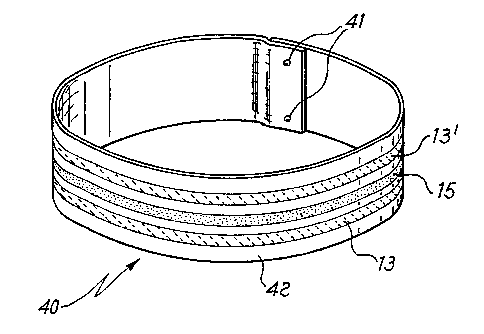
- In figure 4 there is shown a shield 40
manufactured by using the strip of fig. 1, wherein
the tracks are shown to be deposited in a
circumferential direction. The strip of fig. 1 is
cut along the dashed lines with a pitch which is
slightly greater than the shield circumference; the
piece thus obtained is bent as a ring and spot-
welded at points 41, thus forming a complete shield
40 bearing the tracks 13, 13' and 15 on its outer
CA 02209~4~ 1997-07-03
WO97/19461 PCT~T96/0~216
- 18 -
surface 42.
Preferred embo~;m~nts of the shield according to
the invention are obtained starting ~rom the strip
of fig. 2 and shown in the figures 5a and 5b. At the
strip edges two areas 25, 25' are kept free from
deposits of material and left avai~able for the
final welding step of shield production. In this
case the strip is severed by making cuts with a
pitch corresponding to the desired height of the
shield, along the dashed lines of fig. 2. The
obtained pieces are then bent and welded at areas
25, 25', thus obtaining shields in which the tracks
of the various materials are present onto the outer
surface 54 of the shield in a direction parallel to
the axial direction. The possible cross-sections of
the shields are numerous, but preferred are those
-- shown in figures 5a, in which a shield 51 of
circular cxoss-section is shown, and 5b, showing a
shield 52 with substantially rectangular cross-
section. The use of the wide strip of fig. 2 is
preferred ~ecause in this case a wide free area is
available for carrying out the weldings 53 as well
as free areas for welding the shield to the support
keeping it in position within the lamp.
The shape of shield 52 may result particularly
CA 02209~4~ 1997-07-03
WO97/19461 PCT~T96/00216
- 19 -
preferred when obtained starting from a strip having
the cross-section shown in fig. ~. With the shield
52 having an essentially rectangular cross-section
it is possible to locate bends of the piece in areas
free from tracks of materials, thus preventing any
risk at all of loosing particles, which could be
present during the bending. Of course, even though a
rectangular shield obtained from a strip of cross-
section as shown in fig. 3 is preferred, all
combinations of shapes of the shield and cross-
sections of the strip are possible according to the
invention; for instance, it is possible to produce a
rectangular shield starting from a strip having
notches 34, 34',.., but without seats 32, 32', ....
or a shield of circular cross-section using a strip
without notches 34, 34',..., and with or without
- seats 32, 32',... on the outer face of the shield.
In ~igure 6 there is illustrated a cut-away view of
the end portion of a rectilinear lamp, showing a
shield of the invention in its working position.
Lamp 60, electric contacts 61 feeding the electrode
62 with electric power and a shield 63 fixed to a
support 64 are shown in the drawing.
The shields of the invention have many
advantages with respect to those of the prior art.
CA 02209~4~ 1997-07-03
WO97/19461 PCT~T96/00216
- 20 -
The main advantage is that with the shields of the
invention the mercury releasing materials are kept
separate from the getter materials, thus avoiding
possible interferences in the functioning of the
various materials; furthermore, with the shields o~
the invention all the materials are rolled on a
single face of the support, thus avoiding that the
two opposite faces are rolled as required for some
shields of the prior art which are of difficult
manufacture in practice.