Note : Les descriptions sont présentées dans la langue officielle dans laquelle elles ont été soumises.
CA 022l3346 l997-08-l9
W0~7/22770 PCT~S96/20877
--1--
PREFABRICATED CONSTRUCTION PANELS AND MODULES FOR
MU~TISTORY BUILDINGS AND METHOD FOR THEIR USE
Technical Field:
This invention relates to the construction of
multistory buildings employing prefabricated panels and
modules, and more particularly with a method of
construction in which, after the panels and modules are
erected on the job site, concrete is poured to create a
0 structural framework of beams and columns.
Background Art:
Multistory, noncombustible, building construction
typically is of one of five basic structural types or
combinations thereof: reinforced concrete frame, reinforced
wall bearing masonry, structural steel framework, precast
concrete framework, or light gage steel bearing wall. Each
of these methods of construction is subject to cost
disadvantages due to one or more of: time, labor,
materials, weight, and complexity of assembly. Reinforced
concrete frame construction requires the on site labor and
time to build forms for the wet concrete, waiting for it to
harden, and then time and labor to remove the used forms.
Thereupon, the building is completed and finished on site
with expensive job site labor and materials. Reinforced
wall bearing masonry uses concrete block walls held
together with mortar, then reinforced with steel rods and
filled with concrete to produce the bearing walls. This is
reasonably economic in materials and time, but is limited
to a few stories high and then must be completed with job
site materials and labor, at prime cost. Structural steel
or precast concrete framework construction is commonly used
in highrise work, but require the heavy steel or concrete
~ supporting frame structure; the ceilings, walls and all the
interiors to be completed and finished with on site labor
CA 022l3346 l997-08-l9
W097l2277~ PCT~S96/20877
--2--
and materials, a costly construction.
Light gauge steel bearing wall construction employs
framing partitions of light gage steel members assembled
into panels. These members are load bearing and can be
assembled into panels at the job site, prior to erection,
but can be assembled more economically in a controlled
~actory environment. However, the r~m~1n~er of the
building then is completed and finished with costly job
site labor and materials.
0 To some extent, the just discussed methods o~
multistory building can benefit economically ~rom the use
of a combination of prefabricated wall panels and modules,
the modules often including bathrooms and kitchens. Such
panels and modules are not load bearing and are put in
place after the load bearing columns and beams of concrete
or steel are built and the floors laid.
An early patent for reinforced concrete construction
issued to Thomas Edison in 1917, U.S. Patent 1,219,272.
Frederick 4,136,495i Koizumi, et.al. 4,211,045; ~ilnau
4,409,764 and Luedtke 5,048,257 combine the advantages of
reinforced concrete and steel framework by using portions
of the steel framework as non-removable forms for the
poured concrete columns and beams.
Oboler 4,625,484 employs non-load bearing, light
weight floor and wall panels, along with I-beams, etc., to
enable concrete to be poured around the panels to form a
concrete shell.
Grutsch 4,516,372 uses foam plastic wall panels,
positioned spaced apart for concrete to be poured
therebetween to form rein~orced concrete walls.
Sikes 3,698,147 assembles on site hollow metal
columns, each having several parts; then erects the columns
on the foundation. Outer and inner wall panels are
attached to the columns; lastly, the columns are filled
with concrete. The inner and outer wall panels can be
CA 022l3346 l997-08-l9
W097/2277~ PCT~S96/20877
-3
fabricated off site and then on site be connected to the
erected columns, prior to pouring the concrete.
Spillman 3,683,577 casts in place concrete columns and
beams, using wall panels as physical shuttering forms, but
the wall panels have no actual contact with the concrete.
Piazzalunga 4,078,345 prefabricates entire room units,
including kitchens and bathrooms; the walls, ceiling and
floor are of reinforced concrete. The entire room unit is
dropped into place on a foundation having imbedded vertical
o steel beams, which are covered with concrete and define the
perimeter of each room. The room units then are coupLed to
the vertical beams.
Berger 3,751,864 teaches the prefabrication of modular
units, each of which can encompass one or more rooms, and
includes pre-installation of electrical and plumbing needs.
The walls surrounding each unit and its ceiling are of
corrugated steel. During erection of the building, the
modules are positioned next to each other, with spaces
therebetween, and vertical form boards are inserted into
those spaces to complete, with adjacent corrugations,
vertical forms for columns, to be filled with poured
concrete. Similarly, horizontal form boards are secured
below the tops of the corrugated walls of two adjacently
spaced modules and define therewith a horizontal form,
which is filled with concrete to make a ceiling beam.
McWethy 4,525,975 prefabricates modules, such as hotel
rooms, each having a reinforced concrete floor, non-
loadbearing walls, plumbing and electrical lines. The
modules of one level are placed adjacent to each other,
with vertical space between their walls. These adjacent
walls then are latched to each other for maintaining the
vertical space. Thereupon, concrete is poured into the
vertical space to make an entire concrete wall surrounding
~ these sides of the module. After the concrete is hardened
3s to become load bearing, the next level of modules is put in
CA 02213346 1997-08-19
W097/22770 PCT~S96/20877
-4-
place, with the reinforced concrete floor becoming the
ceiling of the lower level module.
Swerdlow 4,338,759 prefabricates wall panels, each
having a plurality of load bearing steel studs and a
plurality of vertical tubes disposed on sixteen inch
centers. In the top of each wall module is a U-shaped
channel which is in fluid comm-lnication with the open tops
of the vertical tubes. After the panels for one or more
rooms are set up on a single floor level and are
o interconnected, a precast concrete ceiling is placed on top
of the panels. The studs in the panels support the
compression load of the ceiling. Thereupon, in a single
pour, the channels and tubes are filled with concrete, and
become load bearing columns and beams, respectively, all
lying within the wall panels.
Mouglin 3,678,638 fabricates room modules off site and
then trucks them to the job site. Hence, the room modules
are limited to tractor trailer width of ten to twelve feet.
The wall and ceiling panels of a room module include a
complex arrangement of steel U and L-channels, which are
welded together to create a reinforcing framework for each
panel and to de~ine portions of open faced forms, T-shaped
for beams and rectangular for columns. At the job site,
room modules for one level are positioned next to, but
slightly spaced from each other, with the open channels
facing each other to complete most of the form portions.
The spaces between modules then are bridged by additional
form members; after which the concrete is poured, to fill
the beam and column forms. After the concrete is
30 sufficiently hardened to be stress loadbearing, the next
level of room modules are set into place.
The above presented prior art, which is a minute
sampling of the vast amount of art, clearly shows a
recognition of the advantages of prefabricated, preferably
factory produced under controlled environment, wall panels,
CA 022l3346 l997-08-l9
wog7n2770 PCT~S96/20877
-5-
room units and modules. Unfortunately, the specific pxior
art solutions have been, to a great extent, impractical and
therefor not utilized. For example, the prior art
teachings require one or more of: units and modules too
large and/or too heavy to be transported from factory to
building site; too many different component parts needed to
be in factory inventory and then be design-selected at the
factory and job site for a specific part of a building,
such design-selection being by experienced and costly
0 labor; the use of unique forms within the panels and
modules for receiving concrete for making therein columns
and beams; the need for on site pouring of large quantities
of concrete to form complete shells around the
prefabricated room units, thus resulting in great
compression force to the walls and supports on the lower
levels, as well as long hardening and curing times.
Summary of the Invention:
The present invention overcomes many of the problems
left unrecognized or unresolved by prior art prefabrication
of wall panels, floor and ceiling panels and core modules,
especially including utility core modules for use in
multistory buildings and methods of erecting such
buildings. One of the ~eatures of the invention is the
2s economical factory fabrication of the more complex core or
utility core portions of a building, such as kitchens and
bathrooms, into a totally completed and loadbearing module;
and transporting and installing this module as a completed
unit. Likewise, it is a feature of this invention to
panelize empty spaces, such as living, dining and sleeping
areas of apartments and motel rooms; which can be
fabricated, transported and erected more economically.
The wall panels, exterior and interior, are prefabricated
~ under controlled environment, factory conditions employing,
for the most part, conventional construction materials and
CA 02213346 1997-08-19
wog7n2770 PCT~S96/20877
-6-
panel configurations. The panel wall boards are affixed to
vertical, light weight steel studs which have sufficient
compression load bearing to support at least one upper
level of room unit wall panels and modules and
floor/ceiling prefabricated panel units, the latter
including thin topping concrete. The wall panels of this
invention are factory fabricated with: insulation,
electrical ~ixtures and wiring, installed exterior doors
and windows, interior door openings, finishes, etc., and
lo are so universally adaptable that only a few variations are
needed for an entire building, for example a multistory
motel. Within most o~ the prefabricated wall panels is
one, or at most a few, hollow, light weight steel column
frames, themselves not load bearing.
Combined floor/ceiling panels of this invention also
are prefabricated at the factory, including a preferred
thin concrete topping floor portion. Except for carpeting
and paint, these floor/ceiling panels are ~inished totally.
They are designed to be laid on top of the edges of the
wall panels, prior to any pouring of concrete.
Core modules are totally built and finished at the
factory, including: all module wall panels, plumbing,
mechanical and electrical features, ~ixtures, wiring and
piping, cabinets, tubs, sinks, ceramic tile, vinyl tile,
paint, etc.
The height, width, depth and weight of the wall panels,
floor/ceiling panels and core modules are designed to fit
onto standard eight ~oot wide flatbed tractor trailers and
be erected with a conventional truck crane. Thus, at least
eighty-five per cent of the multi-story building can use
factory production and not expensive on site construction
time and labor. The foundation is poured on site and can
be a standard concrete spread footing with concrete stem
walls.
The positioning of floor panels on the stem walls and
CA 022l3346 l997-08-l9
W097/22770 PCT~S96/20877
--7--
the one level at a time erecting and positioning of the
wall panels and modules relative to the floor/ceiling
panels define therebetween horizontal voids, which will
become the beams, when filled with concrete. These
voids/beams do not lie inside any of the vertical or
horizontal panels or modules. These voids can be provided
with reinforcing bars just prior to concrete pouring. The
floor/ceiling panels are provided with anchors which
project into the voids. The top and bottom of the hollow
lo steel column frames in the wall panels open into the beam
forming voids. Thus, a single pouring of concrete, for a
specific level of the building, without need of removable
forms, will fill all the beam voids and hollow steel column
frames for that level to create the load bearing column and
beam structural framework and, most importantly, tie all of
the vertical and horizontal panels together as if a
monolithic structure. Moreover, the prefabrication of the
exterior wall panels includes all exterior finishing;
hence, the method of construction of a multilevel building
without use of removable forms enables such construction to
avoid need for external scaffolds or temporary bracing.
To enable a lobby or other large open areas to be
constructed and not require therein columns, walls or other
load supporting elements, but otherwise using this
invention's unique panels and its unique, monolithic
concrete beam-column system and efficient concrete pouring
method, each of the wall panels on the one level above and
overlying the desired large open area is prefabricated to
include a truss member, thus causing those wall panels to
become trussed wall panels for supporting the building load
thereabove. The concrete beams, directly above the large
open area and directly below the trussed wall panels,
cannot support themselves over the long spans of the large
open area. Beam support is provided by utilizing the
vertical reinforcing bars, which normally pass through the
CA 022l3346 l997-08-l9
W097/22770 PCT~S96/20877
-8-
concrete columns in the wall panels into the beams. Those
reinforcing bars are shaped and positioned to hook under
the horizontal reinforcing bars in the beams.
The above mentioned construction components and method
of construction and their benefits will become understood
better in light of the following description of preferred
embodiments of the invention.
Brief Description of the Drawings: ~
lo In the drawings that form part of the description of
the present invention,
Fig. 1 is a top view, in section, of a portion of a
wall panel;
Fig. 2 is an end view, in section, of a wall panel;
Fig. 3 is a perspective, front view, mostly in
section, of the steel frame for a bearing column;
Fig. 4 is a top view, in section, of two exterior wall
panels connected to an interior wall panel; each wall panel
including a concrete filled column frame;
Fig. 5 is a top, plan view of a floor/ceiling panel;
Fig. 6 is a longitll~in~l section of the floor/ceiling
panel, taken along the line 6-6 of Fig. 5;
Fig. 7 is a lateral section of the floor/ceiling
panel, taken along the line 7-7 of Fig. ~;
Fig. 8 is an enlarged view of the right end of Fig. 6
of the floor/ceiling panel;
Fig. 9 is a vertical section through portions of two
levels of wall panels and the interposed floor/ceiling
panels for defining the beam void;
Fig. 10 is a vertical section, somewhat diagramatic,
of the side of various levels of a building, such as a
motel;
Fig. 11 is a top, sectional view of a typical motel
room;
Fig. 12 is a vertical section, similar to Fig. 9,
CA 022l3346 1997-08-l9
W097/22770 PCT~S96/20877
-9-
through two levels of back-to-back utility core modules,
taken along the line lZ-12 of Fig. 11;
Fig. 13 is a vertical section of the beam void,
similar to
Fig. 9, for showing a bearing compression fitting;
Fig. 14 is a top, sectional view of a typical
apartment;
Fig. 15 is a vertical section, of a transverse view of
the building shown in Fig. 10; and
0 Fig. 16 is a vertical section, similar to ~ig. g,
showing especially a portion of a trussed wall panel and a
supported beam below, taken along the line 16-16 in Fig.
15.
Best Mode for Carrying Out the Invention:
One of the basic building blocks, prefabricated in a
controlled factory environment for use in this invention,
is the loadbearing wall panel 2i a preferred embodiment of
which is shown first in Figs. 1, 2 and 4. "Loadbearing",
as used herein with respect to the wall panel 2, means that
this wall panel 2 is capable of temporarily supporting the
compression weight of two levels of floor/ceiling panels
(to be described further below), plus the weight of one
level o~ wall panels and the weight of two beam voids
filled with wet concrete, without the need for any beams or
loadbearing concrete columns. "Loadbearing", with respect
to the panel 2, additionally means that the panel 2 can
support the compression weight of wet concrete poured along
the top of the panel 2, in forming beams of approximately
30 six by twelve inch cross-section, until the concrete in the
beam voids and column frames (shown in Fig. 3) harden and
assume the responsibility of taking all the weight of the
building through the structural beam and column framework
down into the foundation. An alternative construction of
the wall panel 2 can be totally loadbearing, without the
CA 022l3346 l997-08-l9
W097l2Z770 PCT~S96/20877
--10--
need of concrete columns, for lowrise buildings; and can be
used with a relatively few columns for higher buildings.
The loadbearing capability of the preferred embodiment of
the wall panel 2 can be provided by standard six inch,
light gage metal studs 4, of about twenty gage steel,
placed verticalLy in the panel on about sixteen to twenty-
four inch centers. These studs 4 and all of the component
materials and all ~ut two of the component parts used
according to this invention are standard for the building
o construction industry. Accordingly, utilizing this
invention will meet building codes, without special
permits.
The interior wall portions of the wall panel 2 can
comprise a layer 6 of sound deadening or insulation, board,
over which would be wallboard 8, for example 5/8 inch type-
X fire rated gypsum board. These wall boards 6 and 8 are
secured to the studs 4 by conventional means not shown.
Desirably, fiberglass insulation 10 up to six inches thick,
fills most o~ the interior of the wall panel. If the wall
panel 2 is an interior panel, as shown in Fig. 1, then both
sides would be covered with the wall boards 6 and 8. If
the wall panel 2 is an exterior wall, as shown in Fig. 4,
the prefabrication at the factory also will include an
exterior sheathing board 11, in lieu of the sound deadening
board 6, and the complete exterior ~inishing surface
materials 12. Surface materials, such as stucco, alllminllm
siding, vinyl siding, decorative features, reveals 13, etc.
all are made part of the exterior o~ the wall panel 2 at
the factory.
The height of a wall panel would be the height of the
room, for example eight feet. The length of wall panels
would depend upon the room(s) length and width. Typical
apartment and motel configurations utilize walls of
fourteen to twenty-eight feet in length; such length can be
achieved according to the present invention with a single
CA 022l3346 l997-08-l9
W097~2770 PCT~S96/20877
wall panel 2. Although loadbearing wall panels 2 having
~im~n.~ions exceeding eight by twenty-eight feet would not
pose factory prefabrication or on site erection problems,
especially since these panels are relatively light weight,
the factory to job site transportation could affect the
panel size. The bed of tractor trailers are of various
standard sizes to meet intercity, intracity, interstate and
intrastate licensing. Also, in some cities or portions
thereof, the streets might not be wide enough to
0 accommodate extra wide or even wide load or long bed
trucks. Once the job site is known and the transportation
consideration logistics resolved, the architect and
prefabrication management can decide upon the best
selection of panel lengths, one important additional
criteria being employing the fewest panel configurations,
so as to m~xi~i ze the factory prefabrication efficiencies.
For large building projects, the "factory~' could be a
warehouse or merely a covered area adjacent to the job
site, to limit and simplify the transportation logistics.
As shown in Fig. 2, an end view of the wall panel 2, the
top and bottom of each of the loadbearing studs 4 are fit
into basic metal tracks 14 and 16, respectively, which run
the length of the panel. Similarly, the entire panel is
secured, if required for strength, at its top and bottom,
by an optional pair of metal tracks 18 and 20,
respectively. These two sets of tracks 14 and 18, and 16
and 20 can be of sixteen gage and joined by spot welds or
screws, not shown. The inner tracks 14 and 16 also are
secured to the studs 4 by spot welds or screws through the
legs of the tracks. L-shaped guides 21 are secured to the
bottom of the panel by spot welds or screws to the optional
track 20, or to the basic track 16 if the optional track 20
is not needed for rigidity. These guides 21 can be 3/4 by
3/4 inch and are spaced along the length of the panel to
assist in the positioning of the panels by the crane, as
CA 022l3346 l997-08-l9
W097/22770 PCT~S96/20877
-12-
will be detailed hereinafter. An important function of the
optional outer top and bottom tracks 18 and 20 is to
protect the face of the top and bottom of the wall board 8
from damage, especially during transport of the finished
panels to the job site and erection thereat. The cost and
weight of the tracks 18 and 20 can be eliminated if
reasonable care is given to the finished panel 2 during
transport and job site erection. Any small damage to the
bottom of the wallboard 8 can be covered over by baseboard
o type members, often plastic, which would be installed at
the time just after the erected wallboard is painted on
site. The optional top and bottom tracks 18-and 20, or the
basic tracks 14 and 16 if tracks 18 and/or 20 are
eliminated, also are employed to define the lower and upper
limits of a volumetric void that is required for the beams,
as will be described in detail hereinbelow.
A plurality of L-shaped clips 22 ~only one of which
can be seen in Fig. 2) are secured to the center of the top
of optional track 18, or the basic track 14 if the optional
track 18 is omitted. The cLips 22 can be sixteen gage
steel, two inches wide, of two by two inch stock, having a
curved or notched top edge 23 and a large bore 25 through
the upstanding leg. These clips 22 would be spaced about
three feet apart, along the top of the panel 2. The
function of clips will be discussed hereinafter.
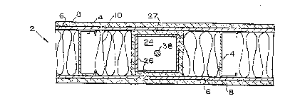
Fig. 3 shows the frame 24 for one of the columns,
which will become the primary loadbearing vertical supports
for the entire building, once the column frame 24 is filled
with concrete and the concrete has hardened. The frame 24
is factory fabricated and installed into the wall panel 2
at the factory. A convenient shape for the main vertical
body of the frame 24 is rectangular or square; five inches
on a side 26 and of light weight steel, such as eleven
gage, or as small as three inches square of 3/16 inch
steel. As seen in Fig. 1, the sides 26 of the column frame
CA 02213346 l997-08-ls
W097/22770 PCT~S96/20877
-13-
24 can be surrounded with gypsum wallboard 27, for example
1/2 inch type-X, to provide added fire protection. The top
and bottom of the frame 24 include two pairs of flanges 28
- and 29, seen in Fig. 3, which are welded to the sides 26
and fit between the wallboards 6 and 8. The flanges 28 fit
- just beneath and in bearing contact with the metal track 14
and the optional track 18 (track 18 is not shown in Fig.
3). The flanges 28 and 29 have the function of
transferring to the column the load of the beam, (not shown
lo in Figs. 1-4), which will lie along the top of the wall
panel 2. The tracks 14 and 18 have large openings 30
positioned over and the same size as the open top of the
frame 24, so that concrete can be poured from above the
tracks 18 and 14 and flow into the column frame, down and
into contact with the previously poured beam of the lower
level. The sides 26 and the bottom flanges 29 of the
column frame 24 can extend into contact with the inner
bottom track 16.
Preferably, the lower end of the column frame 24
includes a bearing box 31 which encircles the frame and its
flanges 29. The bearing box 31 has side walls 32, the top
edges of which are attached to the bottom flanges 29 by
welding or soldering. The side walls 32 seat on top of the
bottom track 16. The bottom flanges 29 can be perforated,
as at 34, to permit air to escape from the bearing box 31
as it is being filled with concrete. The bearing box 31 is
open at its bottom, which lies over a large opening 36 in
~he track 16. Thus, the concrete bottom surface of the
bearing box will be in surface contact with a concrete
beam, which lies directly below the wall panel 2. The
bearing box 31 can be four inches high and be of sixteen
- ga~e steel. The bearing box is attached to the bottom
flanges 29 prior to the column frame 24 being inserted into
- the wall panel 2. The reinforcing bar 38 shown in Fig. 4
3s is installed at the ~ob site, prior to pumping of the
-
CA 022l3346 l997-08-l9
W097/22770 PCT~S96/20877
-14-
concrete. An alternative embodiment for the bearing box 31
is to tightly fit its flanges 29 flush with the bottom of
the bottom track 16 and inside the large opening 36. A
recessed pocket (not illustrated), having a volume similar
to that of the bearing box, is to be made in the beam, ~ust
below the column frame 24 and flanges 29, to receive
concrete as it is being poured to fill the column frame 24.
The recessed pocket could be made by scooping out some of
the previously poured beam, while its concrete was only
o partially hardened. In lieu of the bearing box 31, the
column frame sides can be extended with a compression
absorbing cushion (not shown), for example an elastomeric
bearing pad, which would be positioned between the bottom
of the flanges 29 and the top side of the inner track 16.
An alternative to the bearing box 31 is described with
reference to Fig. 13 and involves the beam void and beam
discussed with reference to Figs. 9 through 12.
Fig. 4 shows, in top section, the T-shaped junction of
two exterior loadbearing wall panels, 2A and 23, with an
interior loadbearing wall panel 2C. Such a junction would
be typical in a motel, with the interior wall panel 2C
being the common wall between two adjacent motel suites.
In an apartment building floor plan, the wall panel 2C
could separate one apartment from another, or be a
loadbearing wall lying between two rooms, such as a living
room and a master bedroom. Near the ends of each of these
wall panels is a loadbearing steel stud 4, through which
project fasteners 40, such as self-drilling cap screws,
such as 1 1/2 inches by 1/4 inch, which secure a sidewall
26 of the column frame 24 to a stud 4. Since the column
frames ~4 in Fig. 4 are positioned at the ends of their
respective panels 2A, 2B and 2C, such frames are identified
hereinafter as end column frames 24, in contrast to the
column frame 24, in Fig. 1, which is positioned remote from
the ends of the panel 2 and therefore called interior
CA 02213346 1997-08-19
WO 97/22770 PCT/US96/20877
--15--
column frames. Because of their end orientations, the end
column frames 24 do not require/possess portions of the
flanges 28 and 29 and the bearing box 31 which are external
to the farthest side 26 of the respective end column frame
24. The securing of the end column frames to the studs is
part o E the factory prefabrication. Installing all of the
column frames 26 into the wall panels 2 as part of the
prefabrication process precisely locates the columns,
simplifies the erection procedure and reduces time and
o additional on site labor costs.
Also included in the prefabrication is the welded
placement of conventional steel stud anchors 42, or
slightly bent rods or bolts, to project outwardly from at
least one side 26 of the end column frame 24. Aligned with
the stud anchors are perforations or small slots 44 in the
side walls 26. During job site erection and alignment of
the various wall panels, the stud anchors 42 of one end
column frame will project through an aligned perforation 44
in the side of an adjacent, abutting end column frame in
another wall panel, as shown in Fig. 4, for ensuring proper
positioning of the wall panels 2A, 2B, and 2C relative to
one another, without need for exterior scaffolds, or
temporary interior bracing, etc. After the concrete 46 is
poured and hardened in the end column frames 24, the stud
anchors are imbedded and held fast in the concrete portion
of the column, immobilizing that column with respect to the
adjacent coLumn frame to which that stud anchor was
originally secured. For example, the anchors 42 projecting
from the wall panels 2A and 2B are inserted through slots
44 and imbedded in the concrete column 48 in the wall panel
2C. The column frames can be provided with standard
reinforcing bars 50. Fire sealing caul k 52 and/or molding
53 can be provided to close any gap that might exist at the
interior corners of abutting wall boards 8.
The vertical reinforcing bars 50, placed just prior to
CA 022l3346 l997-08-l9
W097/22770 PCT~S96/20877
-16-
pouring the concrete at each level, are extended vertically
within its respective column frame 24, from floor to floor,
through the entire height of the building structure, from
the foundation to the roof. These bars 50 are slightly
longer than the length of one floor level height and are
spliced and lapped a minimllm of 30 bar diameters, to create
a continuous structural member to resist all vertical
forces placed upon the building, including uplift.
Accordingly, the column frames 24, fitted with a continuous
0 series of reinforcing bars 50 and filled with concrete 46,
become a column 48 and have the ability to absorb and
distribute the vertical building loads to the foundation.
Since the columns absorb and distribute the vertical loads,
the bearing wall panels 2, both interior 2C and exterior 2A
and 2B, must resist and distribute the horizontal wind or
shear forces acting on the building. One way of designing
the wall panel 2 to resist shear forces is to install a
series of internal "X" steel bracing strapping to both
sides of the steel stud/track framework, prior to covering
the wall panel with any board finishes. Such steel bracing
strapping (not shown in Figs. 1-4 for clarity) would be
designed and screwed or welded in place to the steel panel
framework in accordance with the structural design
requirements; i.e., the various wall panels 2 for a ten
story high building would re~uire much more "X" bracing to
resist wind shear forces than a four story high building.
An alternative construction of the wall panel 2 permits a
more economical building, especially for lowrise buildings,
since it elim;n~tes the need for concrete columns 48 and
their associated column frames 24. By increasing the
strength of the loadbearing studs 4, so that they directly
and permanently support the concrete beams and building
loads above, the concrete columns would not be needed. By
using studs 4 of sixteen or eighteen gage and, if
necessary, securing them back-to-back (as shown with
CA 02213346 1997-08-19
WO97/22770 PCT~S96/20877
-17-
respect to the floor joists in Fig. 7), the studs will
possess sufficient strength to carry the building loads
down to the foundation for lowrise buildings. For taller
- buildings, some few concrete columns are rec~mm~n~ed, so
that their internal, continuous, spliced reinforcing bars
~ 38 are present to resist any building uplift forces. Those
concrete beams with or without the columns would continue
to have the primary task of bonding all the walls, ceilings
and floors into one monolithic structural framework.
o Because of the resulting monolithic framework, some
architects might recommend the presence of a few of the
concrete columns 48 even in lowrise buildings.
Moreover, since the topmost few floor levels of a taller
building are, with respect to load, like a lowrise
building, they can benefit from the more economic wall
panels, lacking concrete columns, or at most having a very
few columns.
A typical floor/ceiling panel 54 is shown in Figs. 5
through 8, including a preferred embodiment, which includes
a thin concrete topping 56 for the floor. The
floor/ceiling panel 54 is constructed and finished entirely
at the factory, except for: carpeting, base molding, a
ceiling cornice which would finish the horizontal edge
where the ceiling meets a wall panel, ceiling trim where
adjacent ceiling panels abut, and paint or acoustic spray
for the ceiling. The structure and many of the components
of the floor/ceiling panel 54 are similar to those of the
wall panel 2. For example, light gage, C-shaped, eight
inch deep, eighteen gage steel joists 58 and 60 run the
lengths of the floor, such length becoming the width of a
room unit of the completed building. The joists 58 are
interior and the joists 60 are at the sides of the panel
54. The length of a floor/ceiling panel 54 might typically
be sixteen feet, but could be as long as twenty-four or
more feet if the apartment, motel, or building
CA 022l3346 l997-08-l9
W097/22770 PCT~S96/20877
-18-
configuratlon required. For convenience of factory to job
site transport, the width of a floor/ceiling panel 54 could
be eight feet; however, if wide or extra wide flat bed
truc~s can be employed, these panels can be of greater
s width. The number of joists 58, their spacing, and if they
are used back-to-back, as shown in Figs. 5 and 7, are
routine design considerations. ~owever, it is to be
understood that no part of these floor/ceiling panels 54
are under loadbearing compression, neither during nor after
erection of the building.
The opposite ends of the spaced joists 58 and 60 are
secured to C-shaped, eight inch deep, steel tracks 62,
which run the width of the floor/ceiling panel 54, as shown
in Figs. 5 and 8. The side joists 60 are secured to the
tracks 62 to make an interior, rectangular frame for the
panel 54. As seen in a broken-out portion of Fig. 5 and
in Figs. 6 to 8, mounted onto the top edge 64 of the joists
58 and 60 is Steeltex~ mesh 66 to cover the entire top
surface of the frame defined by the tracks 60 and 62. Over
the Steeltex~ mesh lies the concrete floor topping 56,
approximately two inches thick, which is poured at the
factory as part of the prefabrication. Secured to the
bottom edges 68 of the joists 58 and 60 are a plurality of
standard manufactured, resilient metal channels 70. By
being resilient, the channels 70 reduce the transmission of
sound through the floor/ceiling panel 54 from one level of
the building to another level. Mounted to channels 70, and
spaced from the bottom edges 68 of the joists 58 and 60 is
the ceiling board 72, for example 5/8 inch type-X
wallboard. The approximate one and one-quarter inch
spacing between the ceiling board 72 and the joist improves
the fire rating of the floor/ceiling panel and also further
reduces sound transmission between levels of the building.
A pair of twelve inch deep steel tracks 74 run the width of
the floor/ceiling panel, parallel to the tracks 62, and are
CA 02213346 1997-08-19
W097/22770 PCT~S96/20877
-- 1~
secured thereto by spot-welds or screws, (not illustrated).
Similar tracks 76 are secured to the joists 60 and form,
with the tracks 74, a rectangular frame around the exterior
- edges of the floor/ceiling panel 54. This rectangular
frame, when filled with the concrete topping 56, can be
- finished economically with a hand screed, using the top of
the tracks 76 as a guide. No power finishing is required.
Stud anchors 78 and steel, L-shaped angle members 80 are
secured to and project outward from the exterior track 74.
o The angle members can have legs of two inches, be one-
eighth inch thick, and extend the width of the floor/
ceiling panel. The horizontal leg 82 of the angle member
80 has, along its length, spaced drill holes 83 shown in
Fig. 8, for reason to be explained hereinafter. As stated
above, the width of a floor/ceiling panel 54 lies along the
length ~im~nsion of a room and is limited by the width o~
the flatbed trailer, which transports it from factory to
job site. Even if a very wide load bed was employed, the
approximate twelve foot panel width would cover only a
portion of the needed floor/ceiling surface. Hence, at the
job site it is necessary to position several of these
panels 54 side by side, with their tracks 76 abutting, to
complete the layout of a single apartment or motel unit.
After several floor/ceiling panels 54 are properly
2s positioned side by side for a specific single level of the
building, the track 76 of one floor/ceiling panel can be
welded at spaced apart points to an abutting track 76 of
the next floor/ceiling panel 54A as shown fragmentary in
the lower right corner of Fig. 5. The tracks, 62, 74 and
76 can be sixteen gage. Although concrete has been chosen
for the preferred embodiment, it and the Steeltex~ can be
replaced by other materials capable of factory
prefabrication of the floor/ceiling panel; for example,
- gypsum can be poured on top of an underlayment board that
is secured to the top edge of the joists.
CA 022l3346 l997-08-l9
W097/22770 PCT~S96/20877
-20-
Fig. 9 is a vertical view through small portions of
two vertically aligned wall panels 2D and 2E of two levels,
for example the second and third levels, of the building
and the adjacent ends of two floor/ceiling panels 54B and
54C, which separate these two levels. The portion of the
building shown in Fig. 9 is shown by the encircled
reference 9' in the building vertical section Fig. 10. For
ease of viewing and understanding the creation of a
volumetric void 84 for a beam, according to an important
o feature of this invention, many of the panel components
shown in Figs. 1-8 are not illustrated in Figs. 9 and 10.
Also, most section shading is omitted in Figs. 9 and 10.
During the erection of the building, for example the second
level, the vertical wall panels, one of which is the
illustrated, interior, loadbearing panel 2D, is positioned
on top of a previously positioned floor level 86 (shown
only in Fig. 10) composed of a plurality of floor/ceiling
panels 54D. Similarly, several other wall panels, exterior
2F and interior, and any core modules required for a
complete room unit 88 are erected by the crane and
positioned to form that second level room unit. Such
positioning will include inserting the stud anchors 42 of
one panel into the open slots 44 of the side 26 of the end
column frame 24 of an abutting wall panel, as described
2s hereinbefore with reference to Fig. 4. Then, the
floorJceiling panels 54, including 54C for that room ~nit,
are lowered into position by the crane to create the
ceiling of the second level and the floor of the third
level. As shown in Fig. 9, the horizontal leg 82 of the
angle 80 helps position the right side bottom of the
floor/ceiling panel 54C onto the optional top track 18, or
the basic track 14 if the optional track is omitted, of the
wall panel 2D. The clips 22, which are secured along the
centerline of the top of the optional track 18, or the
basic track 14 if the optional track 18 is omitted, act as
CA 02213346 1997-08-19
W097/22770 PCT~S96/20877
-21-
positioning alignment stops for the right end of the
floor/ceiling panels, such as the panel 54C, by stopping
the right edge of the leg 82 from movement inward, once the
- leg 82 abutts the clip 22. The thus positioned
s floor/ceiling panel 54C now can be secured to the top of
- the wall panel 2D by screws, which pass into the drill
holes 83, in the legs 82 of the angles 80, and thread into
the tracks 14, 18. Since the leg 82 is two lnches wide and
the centered clip 22 also is two inches wide, the right
o edge of the panel 54C, i.e. its track 74C is approximately
three inches from the vertical center of the volumetric
void 84. At the same time that the right side of the panel
54C is being positioned on top of the wall panel 2D, the
left side of the panel 54C with its angle leg 82 (not
shown) is guided into position on top of a wall panel 2F at
the left side of the room unit 88, as shown in Fig. 10.
Since the loadbearing studs 4 easily can support the weight
of the floor/ceiling panels 54, there is no need at this
time to pour the concrete into the column frames 24, the
sides 26 of one column frame being shown in dashed line, in
wall panel 2D in Fig. 9. At this time, the exterior track
76 of one floor/ceiling panel can be welded to the abutting
track 76 on the adjacent panel; although, such welding and
pumping of concrete could wait until more of the panels
and/or core modules for more of the room units on the same
level are positioned.
Next, the wall panels, for example 2G, and any modules for
an adjacent room unit 96, shown in Fig. 10, are erected and
positioned, so as to be able to support the floor/ceiling
panels for that adjacent room unit, one of those floor/
ceiling panels being 54B, the left end of which is shown in
Fig. 9. At this juncture, the left end of the panel 54B,
with lts track 74B, and the right end of the panel 54C,
with its track 74C, are perched on top of the track 18, or
CA 022l3346 l997-08-l9
W097/22770 PCT~S96/20877
-22-
14 as discussed previously, of the wall panel 2D; ard the
tracks 74B and 74C are spaced apart by about six inches.
Track 18 or 14 thus defines the base of a rectangle and the
tracks 74C and 74B define the vertical walls of that
rectangle; such rectangle being the end view of the
volumetric void 84. As yet, nothing forms the top of the
rectangle. As clearly shown in Fig. 9, the volumetric void
84 does not lie inside of any portion of the wall panel 2D,
nor the floor/ceiling panels 54B and 54C. Also, the
lo vertical tracks 74B and 74C are solid (no openings) and lie
along the entire horizontal length of the void 84. The
tracks 14 and/or 18 run along the top of the panel 2D and
have coincident openings 30 overlying the open top of each
o~ the column frames 24. The wall panel 2D can represent a
plurality of adjacent/abutting wall panels, joined to form
a single, long wall of an apartment or motel unit 88, for
example thirty-two feet long, having therein several column
frames. Likewise, the tracks 74B and 74Cof the floor/
ceiling panels 54B and 54C can represent the tracks 74of
two entire groups of those floor/ceiling panels, which make
up: the second level cellings of two apartment rooms or
motel units 88 and 90, of which the wall panel 2Dis a
co}n~Lon wall; and the f~oors o~ rooms or units 92 and 94 on
the third level, of which the wall panel 2E is a common
2s wall. Hence, the cumulative length of tracks 74B and 74C
also can be quite long, for example thirty-two feet long
made up of end-to-end tracks from the cumulative, side-by-
side relationship of the separate floor/ceiling panels.
Accordingly, the volumetric void 84 would lie on top of an
entire wall, made up of one or several wall panels 2; and
the volumetric ~oid also would lie between the end tracks
74 of two adjacent arrays of floor/ceiling panels 54. Such
position of the volumetric void 84isto become the
position of a horizontal, concrete filled beam 98. The
beam 98, its re~erence number line, parts of the beam and
CA 022l3346 l997-08-l9
W097/22770 PCT~S96/2~877
-23-
thelr reference number lines, to be introduced hereinafter,
are shown in Fig. 9 with short dashed lines to emphasize
that they are the result of filling the volumetric void 84
~ with concrete.
According to a feature of the invention, the pouring
of the concrete can be scheduled so that all the columns
and all the beams for a specific building level, the second
level re Figs. 9 and 10, are poured during the same time
period, a single pour. However, if the construction/
o erection schedule does not enable a single pour per level,
plural concrete pours at different times are accomplishable
without negating the primary advantages of the invention.
As employed herein, the term "pouring" includes pumping. A
preferred construction/erection schedule would complete one
building level per day and provide for the erection of all
vertical components -- loadbearing wall panels, kitchen
and/or bathroom core modules -- and the positioning of all
of the floor/ceiling panels 54 on top of all those vertical
components for that one level to be completed during the
first part of a workday. Such erection and positioning
would include the latching together of the ends of wall
panels, as by the stud anchors 42, and the welding together
the tracks 76 of adjacent sections of floor/ceiling panels
54. Since the floor/ceiling panels are immediately placed
2s upon and, by themselves, brace the corner connected wall
panels, there is little if any need for temporary interior
bracing. Also, since the exterior faces of all exterior
wall panels are finished completely at the factory, there
would be no need for exterior scaffolds. The result of
such first part of the workday erection and positioning
would be as shown in Figs. 4, 9, and the second level in
Fig. 10 except for the concrete 46 shown in Fig. 4 and the
third level wall panel 2E shown in Fig. 9.
During the second part of the first construction day,
reinforcing bars, such as 38 and 50 for the columns 48 and
CA 022l3346 l997-08-l9
W097/22770 PCT~S96/20877
-24-
bars 99, 100 and 101 needed for the beams 98 would be
installed, and any concrete pouring preparation would be
accomplished. The lower, horizontal bar 99 is seated in
the notched edge 23 of the clips 22; and the vertical bars
100 are tie wired to both of the horizontal bars 99 and
101. The installation of the vertical reinforcing bars 38
and 50, which pass through the column frames and the beam
voids (these bars are not shown in Fig. 9) preferably
employ "30 bar diameter" overlap, level to level, to tie
o the levels together and create a complete, reinforced
concrete, monolithic framework. It is to be remembered
that the wall pane~s, such as the wall panel 2E of Fig. 9,
have not yet been erected, nor has any other part of the
third level, other than the ~loor portion of the floor/
ceiling panels 54. The concrete now can be poured/pumped
into the volumetric voids 84 from a position near the top
thereof. Pumping the concrete into volumetric, beam
forming void 84 also causes the concrete to flow into the
top of the column frames 24, by way of the openings 30 in
the tracks 14 and/or 18. As concrete fills the beam void
84, it also fills the large bore 25 in the clips 22 to
provide further anchoring support to the clips, the wall
panels 2 and the reinforcing bars 99, 100 and 101. The
concrete pumping could proceed simultaneously at several
different beam void locations on the same level, so that it
is completed during the second part of the workday, and all
of the column frames 24 and volumetric voids 84 are filled
to make the concrete columns 48 and beams 98 for that
building level. After concrete pouring is completed, which
includes smoothing the top surface 102 of the resulting
beam 98, and the concrete has partially setup, a pair of
vertical grooves 104, which run horizontally along the
entire length of the beam, are made. In the first part of
the following day, the grooves 104 will have hardened to be
able to receive the downwardly directed legs of the L-
CA 02213346 1997-08-19
W097/22770 PCT~S96t20877
-25-
shaped guides 21 for helping the positioning of the third
level wall panels, such as the panel 2E.
It will be appreciated that, during the morning of the
second day of the preferred work schedule, the concrete
poured during the second part of the first day will have
hardened, but is not yet structurally strong enough to
enable the beams 98 and the columns 48 to become a
loadbearing structural framework and assume the role of
carrying the weight of the building down to the foundation.
o This is no problem, since the studs 4 in the wall panels 2
provide sufficient loadbearing to support: those day-before
poured columns and beams, the floor/ceiling panels
perched/set on those wall panels, all vertical panels and
modules of the next level (the third level in this
example), and the floor/ceiling panels which will be
perched thereon. Moreover, even if the columns and beams
poured the first day, second part are not totally
loadbearing by the second part of the second day schedule,
for the pouring on the third level, the loadbearing
capability of those first day columns and beams, combined
with the loadbearing capacity of the wall panel studs 4
erected the first part of the first day (for the second
level) and the first part of the second day (for the third
level) is more than sufficient to support the concrete
pouring of the third level columns and beams on the second
part of the second schedule day. Based upon this preferred
work schedule, an entire building level can be erected and
poured in one day, and the next level can be erected and
poured the next day. To reduce the time by which the
columns and beams of concrete attain sufficient loadbearing
strength, the concrete can be of higher psi. rating, such
as 5,000 psi, rather than the more commonly used 3,000 psi.
Since erection of a level includes its ceiling, and since
windows are included in prefabrication of the exterior wall
panels, some interior work can progress daily on a level,
CA 022l3346 l997-08-l9
W097/22770 PCT~S96/20877
-26-
as soon as erection of that level is completed, independent
of weather conditions and even during the concrete pouring
for that level. Such interior work could include
connection of the factory installed electrical conduits and
plumbing piping to main lines, and installation of all non-
loadbearing walls, which were prefabricated in the factory,
transported to the site, and lifted into place as a
strapped bundle of walls and placed on the previously
erected floor panels of the appropriate living unit, prior
0 to closing the ceiling of that unit with the floor/ceiling
panel above. These interior non-loadbearing walls or
partitions are fabricated similar to bearing walls, but
without the inclusion of any column ~rames. They are light
in weight, with twenty-five gage studs, and can be tilted
up into position by hand, by a separate crew, so as not to
deviate from the accelerated schedule of completing and
weatherproofing the main building structure.
If the number of walls and modules on any one level of
the building is too large for erection to be completed in
the first part o~ a workday, the pouring o~ the columns and
beams can commence where erection has been completed on the
same level, on the same workday; while erection is being
completed during the second part of the same day. After
erection o~ the third level walls and modules and the
pouring/pumping of the concrete for the beams and columns
of the third level, the same procedure is repeated for the
fourth level; and again is repeated ~or each higher level.
Several solutions are available for capping the top of the
building with a roofing system. The structural integrity
of the building must be complete by creating and pouring
all the beam voids 98A to encapsulate the building and thus
bind the various components into a continuous monolithic
structural unit. Three basic solutions are available. One
solution is to cap the building with a flat roof utilizing
a floor/ceiling panel 54 as a roof panel 54E, as shown in
CA 022l3346 l997-08-l9
W~97/22770 PCT~S96/20877
-27-
Fig. 10 with added roofing finish. A second solution is to
add optional, conventional sloping roof members 108, upon
which conventional roofing panels can be secured. The
- conventional sloping roof members would be in addition to
the beam void forming panels 54E. This second method would
allow mansard type roof edges 109 to be accomplished
economically. A third solution, which could be the
preferred solution, would be to modify panel 54E as a
sloping roof system. This roof/ceiling panel would be
0 manufactured similar to the standard floor~ceiling panel
54, as described in Figs. 5-8, with one ma~or exception.
All floor joists 58 and 60 and tracks 76 would be made in
two half parts which are fastened end-to-end with a raised,
rigid or hinged joint 110 at an apex and two identical
sloping sides lllA and lllB, as shown in Fig. 10. The
resulting sloped roof/ceiling bent panel 111 would be
fabricated similar to the floor ceiling panel 54, so that
the end tracks 74 are maintained in their vertical position
to help form the beam void 98A. A finished roofing can be
applied at the factory and the whole, bent, rigid or hinged
panel 111 can be transported and erected rigid or folded in
one piece, without need for any external scaffolds. Once
all of the roofing is completed, the entire building is
water/weather tight and ready for final interior finishing
including: drywall touchup spackling of nicks and blemishes
on the previously finished wall panels and ceiling panels;
spraying on any popcorn ceiling and spray painting the
walls; laying carpeting; hanging prefinished interior
doors; and completing the electrical wiring connections,
air conditioning ductwork connections and plumbing
connections.
- Fig. 10 illustrates one of the various typical
foundations which can be employed with the components and
method according to the present invention. Concrete spread
footings 112 can support a concrete stem wall 114, which
CA 022l3346 l997-08-l9
W097/22770 PCT~S96/20877
-28-
would support the first level of floor panels 54F. The
floor panels 54F would be prefabricated the same as the
floor/ceiling panels 54 in Figs. 5-8, except that the
resilient channels 70 and the ceiling wallboard 72 are
omitted. The bottom edge of the volumetric beam voids 84
for the first level is defined by the top surface 116 o~
the stem wall 114, since there is no wallpanel 2, with its
track 18 below the floor level 54F, as there is in the
second and higher levels, as previously was described and
o shown in Fig. 9.
The outside faces 118 of the beam voids 84 require
some form-like element while concrete is being poured and
until it has hardened. For the first level beam voids, a
standard, temporary form 120 can be used and then removed.
However, this is not acceptable for the upper levels, since
a goal of the present invention is the exclusion of
exterior scaffoIds. A solution for this problem is to
factory install an external metal track 122, also shown in
Fig. 2, hinged or flxed, so that in its final position it
completes the forming of the beam void.
A top, sectional view of a typical motel room is shown
in Fig. 11, such as the third level room unit 92 in Fig.
10, with a small portion of an adjacent room unit 94. The
motel room 92 has two main portions, a living/sleeping
25 ~portion 124 and a core module 126 which encompasses a
bathroom/entry/closet portion. The living/sleeping portion
124 contains all of the structural components illustrated
and described heretofore, except for the footings, stem
walls and roof. Commencing with the left wall, it is
formed by one or a series of end connected, exterior.
loadbearing wall panels 2A, with light gage studs 4, sound
deadening and wall boards 6 and 8, fiberglass insulation
10, exterior sheathing board 11, finishing 12, reveal 13,
at least the basic tracks 14 and 16, the column frames 24
(interior and end) filled with concrete 46, the
CA 022l3346 l997-08-l9
W097/22770 PCT~S96120877
-29-
interconnection cap screws 40 and stud anchors 42, etc.,
etc. Underlying the wall panels 2A is the beam void 84
filled with concrete to constitute a beam 98 running the
- entire length of the room 92. The concrete for the beam 98
was poured at the same time as the concrete which filled
the column frames 24 for the columns in the panels 2 in the
lower level room units 88, 90 and 96.
The long wall on the right side of the room unit 92 is
an interior/common wall made of one or several end-to-end
o interior, loadbearing wall panels 2C, of the type shown in
Fig. 1, with the sound deadening and Type-X wallboards 6
and 8 on both sides thereof and the construction components
just above mentioned for the left wall. Within the circled
reference 3' is an interior column frame 24, shown in Fig.
3. The exterior lateral wall is of the 2A type, was
prefabricated with a finished window 128 and an opening 130
for receiving an air conditioning unit 132. The corner, to
the right of the A/C unit 132, where wall panels of the
type 2A, 2B and 2C are joined together, is similar to that
which is illustrated in detail in Fig. 4 and is identified
by the circle reference 4' in Fig. 11. The circle
reference 5' points out the floor portion of the
floor/ceiling panel shown in Figs. 5-8. The long dashed
lines 76, one of which passes through the clrcle 5',
designates the exterior tracks 76 of two of the
floor/ceiling panels which are secured to each other, to
join two of the floor/ceiling panels 54.
The length of a room unit is not dictated by the
length of room units adjacent, below or above it. Also,
the exterior end of a room unit can be extended to include
a balcony; these two features are shown in the top of Fig.
11. Beam voids and their resulting beams, such as 98B and
98C, are extended and cantilevered from the longitudinal
beams 98 to extend outward from an exterior wall and be
covered by a prefabricated concrete slab 134, or a floor
CA 022l3346 l997-08-l9
W097/22770 PCT~S96/20877
-30-
panel similar to the floor/ceiling panel ~4, but with a
weather-tight lower surface replacing the ceiling board 72,
to form a balcony. Although the beams 98B and 98C are
cantilevered and require the use of removable forms, there
is no need for exterior sca~folds. Presence of the balcony
would require the window 128 to be a sliding glass door,
prefabricated and installed o~f site into its exterior wall
panel. If the room unit 94 is to be longer than the unit
92, its longitudinal beams, one of which is 98C, can be
o extended in the same way as the balcony beams 98B and 98C.
Of course, other of the construction components, including
side walls, floor and ceiling, also would be longer, and
the exterior wall 2B would be moved outward to the position
2B'. The bottom surface o~ balconies and extended rooms
would be ~inished suitably. The presence of different room
unit lengths and balconies allows for variation in the
design of the facade of the building.
A core module, one example being the bathroom 126 in
Fig. 11, according to the present invention, utilizes many
of the pre~abrication techniques and components described
hereinabove and obviates prior art complexity and cost.
The advantage o~ a core module, such as the bathroom 126,
is that it is totally prefabricated. Tiled ~loor, celling,
walls, tub/shower enclosure, sink, toilet, mirrors, all
plumbing pipes and electrical outlets, conduits and
fixtures are assembled off site into one totally ~inished,
six sided, modular unit; ready to be set into ~inal
position by the job site crane. The major disadvantages of
prior art modules did not pertain to their prefabrication
and transport, but were caused by their installation
requirements. According to the prior art, the modules were
selfsupporting, but were not loadbearing; they could not
support the weight of modules or rooms or steel/concrete
~ramework above them. Hence, the prior art six sided
modules had to be placed into a loadbearing framework or
CA 022l3346 1997-08-l9
W097/22770 PCT~S96/20877
shell, which already was part of the building being
erected; or a loadbearing framework or shell had to be
formed around the prefabricated module just after it was
set into the building, as it was being constructed. This
effectively created a box within a box; thus requiring
considerably more work, materials and weight--hardly much
of an advantage when using modules. Or, if the module was
of heavy concrete shell type and could support additional
modules above, then it would be extremely heavy and large
and be difficult to transport. Core modules, according to
the present invention, are loadbearing, since their wall
panels 2 contain the loadbearing studs 4 and the column
frames 24, which will be filled with concrete and thereby
become loadbearing. Or, in the alternative, as earlier
discussed, the studs can be of the increased strength,
thereby obviating the need for the concrete columns, or
reducing the number of the columns. Components of the
modules define the volumetric beam void 84, which is filled
with concrete to form the beam 98. In fact, from an
~x~mination of Fig. 11, the bathroom portion core module
126 does not look to be of different construction than the
living/sleeping portion 124, except for the narrow side-by-
side walls 2H and 2I, which lie on top of the beam portion
98D, which is contiguous with beam 98, which underlies the
entire right side of the room unit 92 and the left side of
the room unit 94. As is well known, to simplify plumbing,
bathrooms of adjacent room units are positioned back-to-
backi also, they are vertically aligned floor-to-floor.
The core modules shown in Figs. 11 and 13 span the full
width of a room--span from bearing wall to bearing wall.
Core modules can be shorter or longer and span across and
interrupt a bearing wall if the plan layout so dictates.
An example would be two bathrooms back to back serving two
living units and factory fabricated into one module for
economy. In this case the bearing wall separating the two
CA 022l3346 l997-08-l9
W097~2770 PCT~S96/20877
-32-
living units would be interrupted by the intersecting
module. This presents no problem structurally as long as
the beam void continues into the perimeter o~ the module,
completes the beam void along both sides of the module and
connects it into any adjacent bearing walls that abutt the
module. This encapsulates the module and binds all the
beam voids of a particular building level into one
contiguous, monolithic, structural unit.
The vertical, sectional view in Fig. 12, which is
lo taken along the line 12-12 in Fig. 11, provides more
information concerning the construction features of the
core module wall panels 2H, 2I, 2J and 2~, ceiling and
floor members 54G and 54H and their small differences from
the wall panel 2, shown in Figs. 1-4, and the floor/ceiling
panel 54, shown in Figs 5-8. The essence of the
di~ferences in the major components is that the bath module
126 and all other core modules according to this invention
are six sided and, there~ore, do not share a common wall,
or a common ceiling or floor with an adjacent core module.
Thus, the bathroom module 126 in motel room 92 requires a
wall panel 2H, which is prefabricated as one of its
module's six sides; and it is fabricated totally separate
from the similar wall panel 2I in the six sided bathroom
module 136 for the motel room 94, as is shown in Figs. 11
and 12. The bathroom module 126 in Fig. 11 is at the
corner of the motel and, therefore, only the wall panel 2H
is adjacent another core module; hence, the remaining
loadbearing wall panels 2 of this module are either
interior, as shown in Fig. 1, or exterior, as illustrated
in Fig. 4. So that the beam void 84D and the resulting
beam 98D running below the wall panels 2H and 2I have the
same six inch width as all the other beam voids and beams
in the motel building, the wall panels 2H and 2I are
approximately one-half the width of the previously
described wall panels 2. Thus, the loadbearing studs 4H
CA 022l3346 l997-08-l9
W097/22770 PCT~S96/20877
-33-
and 4I are two and one-half inches wide and are set into
two and one-half inch wide steel bottom tracks 16H and 16I.
Likewise, the top of the studs, such as shown as 4J and 4K,
over which the beam 98D is positioned, are set into top
tracks 14J and 14K. The wall panels 2J and 2K are part of
two other back-to-back core modules 138 and 140, located at
the ends of the motel rooms 88, and 90. As is well known,
to simplify plumbing,=bathrooms of adjacent room units are
positioned back-to-back; also, they are vertically aligned
lo floor-to-floor. There are no optional tracks 18 and 20.
The L-shaped guides 21 are secured to the bottom tracks 16H
and 16I and their respective floor tracks 74, to facilitate
factory fabrication of the totally enclosed modules. Since
the core modules are totally finished as part of their
prefabrication, bathtubs 142, and floor tile 144 are part
of the bathroom module 126, as well as sinks, toilets,
mirrors, wall tile, light fixtures, floor and wall cabinets
(not illustrated), etc.
Since core modules are not limited to encompassing a
single room, such as a bathroom or a kitchen, a core module
can encompass, for example, two back-to-back bathrooms 126
and 136 in the motel units 92 and 94. In such an
arrangement, the narrow wall panels 2H and 2I could be
replaced by a single common interior wall panel 2. Such a
core module need not include the entry and closet portions
of the rooms.
Each core module has its own floor panel 54G and its
own ceiling panel 146. As shown in Fig. 12, the floor
panel 54G is almost identical to the floor portion of the
floor/ceiling panel 54 shown in Fig. 8. The floor panel
54G is composed of an eight inch wide steel joist 58, set
within a pair of C-shaped, eight inch interior tracks 62,
which are secured to two pair of C-shaped exterior tracks
74 and 76, which frame the floor panel 54G. Steeltex~
mesh 66 is secured to the top edge 64 of the joists. About
CA 022l3346 1997-08-l9
W097/22770 PCT~S96n0877
-34-
two inches of concrete topping 56 is poured on top of the
Steeltex mesh and is the smooth base for the tile 144.
Also, stud anchors 78 are secured to the exterior track 74
The L-shaped angles 80 are secured as also shown in Figs. 8
and 9, so as to butt against the side edges of the clips
22. The ceiling panels 146 of a core module comprise a
light gage steel joist 148, for example six inches deep,
set into a frame of six inch, C-shaped steel tracks, of
which the tracks 150 are shown in Fig. 12. The top o~ the
0 ceiling panel of a core module, ~or example the bathroom
module 138 of the second level room unit 88, is
approximately two inches below the top of its wall panel 2J
(as well as below the top of the adjacent wall panel 2K o~
the module 140 of the room unit 90). Thus, the side tracks
150 of the ceiling panels 146 o~ a core module cannot form
any part of the beam void 84D. Only the side tracks 74 of
the floor panels 54G define the vertical sides of this beam
void. The bottom surface of this beam void 84D is defined
by a closure plate 152, which can be sixteen gage and is
secured to the top faces 154 and 156 of the top tracks 14J
and 14K. The closure plate is prefabricated with attached
two by two L-shaped clips 22, as previously described and
shown in Fig. 2, and is pre-punched with openings 158,
positioned over any column frames, such as 24J in Fig. 12.
The openings 158 are for the same purpose as the openings
30 in the tracks 14 and 18 discussed with Fig. 3--to
establish an opening into the top of the column frames for
pumping therein the concrete. This enables all beam and
column members in the core modules to be contiguous
throughout the vertical height of the building and also to
be contiguous with all other of the beams and columns in
the same and all other levels of the building; thus forming
a single, unitary, rein~orced concrete ~ramework.
Wallboard 160, ~or example 5/8 inch Type-X, ~inished as
required, is secured to the lower edge 162 of the joists,
CA 022l3346 l997-08-l9
W097/22770 PCT~S96/20877
-35-
to form the ceiling. The walls of the modules can include
sound deadening board 6 and finished Type-X wallboard 8,
unless other wall finishes are specified by the builder.
- Because of t~e narrow, two and one-half inch, width of some
of the module studs, such as 4J and 4K and the resulting
narrow wall panels 2J and 2K, there is insufficient space
to place a full size, five inches square or rectangular,
column frame 24 or even a smaller three inch column frame
within one of these wall panels. Moreover, the column
frame and its resulting loadbearing column should be
centered with respect to the vertical axis of the beam 98D.
To accommodate for these needs, as shown in Figs. 11 and
12, the column frames, such as 24H and 24J, are secured
within one of the side-by-side module wall panels, such as
2H and 2J, and project between the studs 4I and 4K of the
adjacent wall panel, 2I or 2K, respectively. Since the
entire floor of a particular room unit, such as 92 in Fig.
10, is to be installed completely prior to the pumping of
any beam voids 84 at that floor level (the third level in
Fig. 10), then all the fLoor/ceiling panels 54 in the
living area 124, and the floor panel 54G of the core module
126 are to be put in place prior to pumping the beam voids
associated with that floor. However, when the bathroom
core modules 126 and 136 are in place, the beam void 84D
defined by the floor tracks 74 and closure plate 152 of the
moduLes 126 and 136 is not accessible for pumping from that
floor level. Since the beam voids which form the perimeter
of a particular room unit should be filled with one
uninterrupted continuous pour, filling of the beam void 84D
can best be accomplished by pumping into the top of the
column frames 24H, which are shared by the two modules 126
and 136 and are spaced within the module wall panels 2H and
2I. Once the beam 98D is poured, then the remaining beam
voids 8g surrounding the perimeter of the living portion
124 can be pumped from the floor level directly, as
CA 022l3346 l997-08-l9
W097/22770 PCT~S96/20877
-36-
described previously. As a consequence, for a specific
building level, the installation of a core module precedes
by one full, two part, construction/erection cycle the
erection of the wall panels 2 and the floor/ceiling panels
54 set onto their tops for the non-module portions of that
same building level. Hence, when concrete is poured for
the beams of a specific building level, the columns, which
are a part of a module and rise above those beams also
partially are poured. For example and with reference to
o Figs. 10-12, when the second level rooms 88, 90, 96, etc.
are being erected with their wall panels ZF, 2D, 2G, etc.
and their ~loor/ceiling panels 54C, 54B, etc. during a
first part of a construction cycle, the bathroom module 126
for the third level room 92 also is positioned, so that its
floor panels 54G are horizontally aligned with the
floor/ceiling panels 54B, 54C, etc., at the top of the
second level. Then, during the second part of the same
construction cycle, the concrete is poured into the beam
voids 84 for creating the beams 98, 98B and 98C, which lie
20 along the top o~ the rooms 88, 90, 96, etc., and concrete
also is poured then into the top of the column frame 24H of
the core module 126 for creating the beam 98D, within the
beam void 84D, which was defined by the floor panels 54G
and their closure plate 152 of the module.
In some instances, especially in buildings of many
floors, the allowable compressive bearing strength of the
concrete beam 98 might be exceeded where it horizontally
passes between the vertically aligned column frames 24,
filled with concrete, which define the loadbearing columns
48. In such case, the architect or structural engineer can
employ a bearing, compression fitting 163, as shown in Fig.
13. This Fig. 13 is a repeat of Fig. 9, with certain
components of Fig. 9 not shown, for enhancing the
illustration of the compression fitting 163. The
compression fitting 163 lies in the beam void 84 directly
CA 022l3346 l997-08-l9
W097/22770 PCT~S96/20877
-37-
in vertical alignment with the column frames below and
above it, for example the column frames 24D and 24E and
their columns 46D and 46E, in their respective wall panels
- 2D and 2E. The task of this compression fitting is to
s transfer the building loads directly from an upper column,
such as 46E, down through this compression fitting and into
the underlying column, such as 46D. Three components make
up the compression ~itting, a pair of legs 164 and a top
bearing plate 165. The legs 164 can be cut from a standard
lo four inch steel channel; and the top bearing plate 165 can
be of three-eighth inch steel. The tops of the legs are
welded to the bottom side of the bearing plate. The
overall height of the compression fitting is to be equal to
the height of the beam void 84, so that the top surface of
the bearing plate 165 is in surface contact with the bottom
surface of the flanges 29E. The flanges 29E are the only
components of the bearing box 31 employed when using the
compression fitting 163. Also, the flanges 29E are to
extend out from the bottom of the column frame 24E, since
there are no sides 32, as shown in Fig. 3. The bearing
plate 165 has a centered opening 166, which would be
aligned with the opening 36 in the track 16 of the wall
panel 2E, and the opening 30 in the track 14 of the wall
panel 2D, so that the reinforcing bar 38 will pass totally
through the fitting 163 and be spliced with other
vertically aligned reinforcing bars in the wall panels 2D
and 2E. The assembled compression fitting 163 is installed
in the beam void 84 prior to the pumping o~ concrete
therein; the pumped concrete would become contiguous with
that of the columns 46D and 46E.
Fig. 14 depicts a typical apartment 167, having two
~ bedrooms 168 and 169, each sharing a single back-to-back
bathroom core module 170 with its bathrooms 171 and 172; a
- large living/dining area 174; a core module kitchen 176;
and a balcony 178. Also shown is an exterior corridor 180.
CA 022l3346 l997-08-l9
W097/22770 PCT~S96/20877
-38-
This apartment 164 would consist of all of the factory
prefabricated panel, modules and components described
hereinabove and illustrated in Figs. 1-13. Most
importantly: the method of defining the beam voids;
creating light weight steel column frames, which become
bearing components when filled with concrete; using
loadbearing studs in the wall panels; and avoiding exterior
scaffolds, contribute to lower costs, faster erection and
completion and a totally satisfactory, high quality
o building. The overall size of the apartment 167 is
approximately thirty feet wide and forty-four feet long,
including two spans 182 and 184, fourteen and sixteen feet,
respectively, with three beams 98E, 98F and 98G running the
lengths of these spans. Of course, an apartment can be
composed of many more than two spans and, there~ore, be
much wider than thirty feet; and also be as long as one
wants, by use of the end-to-end wall panels and many
sections of the floor~ceiling panels. The exterior
corridor 180 is constructed similar to the balcony 178,
2~ with on-site extended, cantilevered beams 98B and
reinforced, concrete slabs, as discussed with reference to
the balcony 134 in Fig. 11.
The apartment 167, as well as the motel unit of Fig.
10, contain some non-bearing, interior wall partitions,
factory prefabricated and finished, as previously
discussed. Examples of these partitions are closet walls
186 in Fig. 14. These wall partitions also can be used to
enclose vertical chases 188, for plumbing and/or other
utilities. A chase can be built within a core module,
shown as 190 in the bathroom module 126 in Fig. 11.
Typically, most apartment buildings, hotels and motels
have lobbies, foyers, meeting rooms, and other large open
areas, which should not be divided by wall panels, nor be
interrupted by load supporting columns. Conventional on-
3s site construction could be used to build the large open
CA 022l3346 l997-08-l9
wo97n~770 PCT~S96/20877
-39-
areas, but at a greater cost and at loss of the time
efficiency of the present invention. However, with small
modification to certain of the wall panels 2, to make them
into trussed panelsi and by using beam supporting
reinforcing bars depending from associated wall panel
columns, the construction method and components set forth
hereinabove, with reference to Figs. 1-14, can be employed
to their full advantage to define the desired, inventive
monolithic load supporting framework system having therein
lo large open area rooms, as well as normal sized rooms,
units and apartments.
With reference to Fig. 15, a vertical section through
the building shown in Fig. lO, but at right angle to it,
i.e. a transverse view, let it be assumed that on the first
level there is to be an open area lobby 192 below the rooms
88,90 and 96 (shown in Fig. 10). The left end of the lobby
192 will be at the end of the building. Since the lobby is
to be an open area, without supporting wall panels 2 or
columns, the load of the building from above would be too
great to be supported by only the outside left wall, with
its wall panels 2 their studs 4 and their concrete filled
column frames 24, and also the load supporting walls and
columns vertically aligned with the right side of the room
96 -- from ground to roof, with their respectively
associated beams 98. With reference to Fig. 14, and
assuming its apartment 167 also is the room 90 in Fig. 10,
the lobby 192 would have no load bearing wall panels 2 or
even columns aligned under and thereby supporting the walls
194, 196 and 198, which run the entire length of the
apartment 167. Nor would there be in the lobby any
supporting walls or any support members under the walls
corresponding to wall 196 in rooms 88 and 96.
The absence of wall-column support in the lobby 192
can be replaced by a modification of the wall panels
forming walls 194, 196 and 198 in the overlying rooms 88,
CA 022l3346 l997-08-l9
W097/22770 PCT~S96/20877
-40-
90 and 96, by fabricating those wall panels as trussed wall
panels 200, designed as a girder truss, shown in Figs. 15
and 16. Such trussed wall panels 200 are to be fully
fabricated of~ site -- at the factory -- as are all of the
wall panels 2. A diagonal chord member 202, preferably of
steel, is welded to similar top chord and bottom chord
members 203 and 204, which are secured to tracks 14 and 16;
these tracks having been previously described with
reference to Figs. 2 and 3. Although the chords 202, 203
o and 204 could be cut from a steel angle of suitable
~;~Pnsions and strength, the shape and material of the
column frame 24 (shown in Figs. 1 and 3) meets the
structural needs and is easily fabricated to correct
length. The trussed wall panel 200 would be designed
according to basic engineering practice, which includes use
of basic truss principles ~or defining the size, type and
location of the truss chord members. As shown in Fig. 15,
the studs 4 are present, but are interrupted by the
diagonal chord 202 and are secured to the top and bottom
chords 203 and 20~. They no longer are the needed for load
support. Further support, if needed can be provided by
additional column ~rames 24' adjacent to the end column
~rames 24, in one or both the ends of the lobby and in the
wall panels 20~ lying directly thereover, as shown in Fig.
15.
The trussed wall panels 200 will support the building
loads thereabove, remembering that they will contain the
studs 4 and the concrete columns 46 in the steel frames 24.
However, and with reference to Fig. 9, the concrete beam 98
lying between the floor/ceiling panels 54B, 54C, just below
the wall panel 2E, i~ it was a trussed wall panel 200,
could not support itself without a supporting wall panel 2D
or other supporting members or columns. To solve this new
problem, the vertical reinforcing bars 38 ~shown in Figs.
3~ 1, 3 and 4) are formed with a depending hook 205 and, as
.
CA 022l3346 l997-08-l9
W097/22770 PCT~S96/20877
-41-
shown in Fig. 16, will be positioned just hooked below the
horizontal reinforcing bar 99 (first shown in Fig. 9), to
lock into and support those beams which are just above the
~ lobby 192.
The erection and pouring method described hereinabove
with reference to Figs. 1-14 also is to be followed when
using the trussed wall panels 200 and the reinforcing bars
having the hooks 205. Those reinforcing bars would be the
bottom/lowest of the 30 bar diameter overlapped bars 38 and
o would be set into the positions shown in Figs. 15 and 16,
relative to the horizontal bars 99, during the first part
of a "first" day, prior to pouring concrete, on the second
part of that day. Such pouring, as previously described,
would be from above and into the beam voids 84, just above
the lobby 192; and would flow down through the column
frames 24 in the bearing wall panels 2 surrounding the
lobby 192, down to the ground floor 206. However, at that
time of pouring, the hooked reinforcing bars have no beam
supporting ability, since their upper ends 208 are not
encased in hardened concrete. That encasing concrete will
not be poured until the next day and will not be
sufficiently hardened for at least another day thereafter.
The needed beam support, during erection and pouring around
and directly above the lobby 192, as well as during the
next day's erection of the trussed walL panels 200 and the
pouring of the beam overlying them, down into their column
frames 24 to encase the upper ends 208 of the reinforcing
bars 38, and for at least the next day, until the hooked
bars can support the beams 98, is provided by temporary
wall panels 210 which are erected during the first part of
the "first" day, when other wall panels 2 are being erected
around the periphery of the lobby and at all other
locations on the first level, for defining walls of rooms.
With reference to ~ig. 9, if the floor/ceiling panels 54B,
54C were to overlie the lobby 192, then the wall panel 2D
CA 022l3346 l997-08-l9
W097122770 PCT~S96/20877
-42-
would be a temporary wall panel 210. As shown in Fig. 15,
one or a series of the temporary wall panels 210 form
temporary walls aligned below the trussed walls formed by
the trussed wall panels 200. With reference to Fig. ~4,
the trussed wall panels are aligned one level below the
longitudinal running walls 194, 196, 198, etc. in the rooms
88, 90, 96 and the temporary walls defined by the temporary
wall panels 210 are aligned below the trussed wall panels
200.
o The temporary wall panels 210 can be fabricated
similar to the wall panels 2, having the loadbearing metal
studs 4, but they do not require the: column frames 24,
outer tracks 18, 20, sound deading board 6, insulation 8,
exterior finish-12, guides 21, clips 22, nor wall board 24.
After the concrete beams 98 and columns 46 overlying and
surrounding the lobby and those columns in and beams just
above the trussed wall panels 200 have sufficiently
hardened to support the beams 98 just above the temporary
wall panels 210, the temporary wall panels can be removed
and the lobby can be decoratively finished. Thus, the
creation of the large area, lobby, has not importantly
modified the scheduled work -- two parts per day, erect and
then pour --; certainly has not slowed the work schedule;
and has not required on site construction of components,
2s nor even use of significantly different component parts.
Considerable detail has been set forth hereinabove with
respect to: the method of prefabrication of components, the
components themselves, the loadbearing wall panels, the
floor/ceiling panels, the method of erection of rooms, the
creation of the beam voids, the fabrication and use of
loadbearing core modules, and the resulting monolithic,
reinforced concrete framework. However, certain of the
details can be modified by those skilled in the art, while
r~m~ i n ing within the theme and scope of the invention
herein. Moreover, the novel formation of the beam void can
CA 02213346 1997-08-19
W097/22770 PCT~S96/20877
-43-
be incorporated advantageously into building construction
of various types and lie within the spirit and scope of my
invention as claimed.