Note : Les descriptions sont présentées dans la langue officielle dans laquelle elles ont été soumises.
CA 0221637~ 1997-09-24
WO9G/29896 PCT~S96/04256
DROPPER A8SEMBhY FOR T~IQUID FEED
AND METHOD OF FEEDING LIQ~ID
COMPO8ITION TO A FREEZING CHAMBER
Technical Field
The present invention relates generally ~o
preparing a frozen product and, more particularly, to
a dropper assembly for liquid feed and a method of its
use in feeding liquid composition to a freezing chamber
during preparation of a free-flowing frozen alimentary
dairy product.
Backqround of the Invention
Sales of ice cream and frozen yogurt products
have risen dramatically in recent years. The applicant
herein has captured a portion of this product market
through the development of a unique novelty ice cream
and frozen yogurt product in the form of beads. This
product, marketed under various trademarks, including
DIPPIN' DOTS, and ICE CREAM OF THE FUTURE, has become
very popular in specialty stores and at fairs and theme
parks.
This novelty ice cream and frozen yogurt
product is prepared by delivering flavored liquid dairy
composition to a feed tray and then dripping the
composition into a freezing chamber. The droplets of
liquid composition freeze rapidly upon entry into the
freezing chamber, forming solid beads of flavored ice
cream or yogurt product. The frozen beads are removed
from the freezing chamber and packed for distribution
CA 02216375 1997-09-24
SEP. 23.1597 3: 24PM THMS~KDEN~H51~K~Y NO. 773 P. 2
~I~J~3.~13g7 14:E~6 ~06:~!241399 STOCI~JELL LA!.'1 ~FCS PA~E el5
W~ID896 ~ C~ b~
The praparatioh o~ ~he no~ y ice ~e~ and
yogur~ p~o~uc~ ide~lly ~a~ls the ~livery of
unlfor~y 5i~d dro~let~ in ~rder ~ form con~ el.Ll~
uhiform bead~ d~ir~bl~ ~o el~min~ the liqu~d
particle~ or ~ cl~ that tQnd to }~ ~lea~ad fro~ e
~e~d ~ay, ~I?h~ eh, when ~rozen, ~or~ p~ic~ in the
~ 4 of ~i~ ~ ea~l~ anaJor du~t ~ ~Che ~roz~n due~
not only undn~irable in ~ nce, ~U~ o ad~ ly
afPect the coll~tion o~ ue~l~ p~odu~. ~huG, t~e
~ormation of frozen dus~ ol~ in~fficieney in~o
~he ~o~-~s o~ prepar~ng the fr~zen ~aded ;ce ~e~
~nd ~gurt product. ACCOLaing1Y, a need i~ iden~i~ied
~o cr~ a ~ay to e~ ~e the for~ation o~ ~ozen
~ d~t and ~1C~P~ead-~ duxing pxoduct manuf~u~e~ It h~
~e~n deto~ ou~h exp~rimen~ lon th~t ~e
con~gur~tion of the ~eed ~le~ent6 aGsociate~ wi~h the
~sed t~y ~ ~ direct ~feet on the de~-red re~ult.
s~ Ar~ of ~he ~n~n~ion
~t i8, the~efore, a pr$ha~y obj~ct of ~he
pre~e~t $nven~ion to pro~i~e a ~ophi~t~cat~d, frozen
d~iry pL ~duc~ hav$n~ ~mprove~ ~lavor and ~ass con~um~r
appe~.
Anoehe~ objec~ o~ ~;h~ p~e~e~t in~ention ls to
pr~vide a free-~lo~ny frozen ~linlenl;ary d~ry ~ro~ t
whie~h i5 erved a~ a r~at~vely low temperat~re so as
tc be mor~ refreshlng and exhilara~i~g to t~e a~rera~e
consumer.
St~I another o~ec~ of t~e present in~ention
is to p~ovide a method o~ preparing ~ free-fl~win~
~ozen ~ n~ary ~ai~y ~L~U~ h ~S ~ui~ly frozen
~! 0 ~L5 to l,~ev~.~ the for2nat~,~n of large içe cryst:al~
and ~ereby pro~ide a s~oother p~oduct with b~ter
~lavor. ;,
I~ is ~ fu~ther obje~t o~ the Present
CA 0221637~ 1997-09-24
w096/29896 PCT~S96104256
invention to provide a dropper assembly for feeding
liquid composition to a freezing chamber that
substantially eliminates the formation of frozen
microbeads and/or dust during the production of a free-
flowing frozen alimentary dairy product.
It is a further object of the presentinvention to provide a dropper assembly that easily and
efficiently handles liquid feed.
Another object of the present invention is to
provide a method of feeding liquid composition to a
freezing chamber with enhanced control over the size of
the feed droplets to yield uniformly sized frozen
beaded product.
It is an additional object of the present
invention to provide a method of feeding liquid
composition to a freezing chamber in the form of
uniformly sized droplets whereby increased frozen
product yield is achieved.
Still another object of the present invention
is to facilitate production of a free-flowing frozen
alimentary dairy product at a reduced cost and with
increased efficiency.
Additional objects, advantages and other
novel features of the invention will be set forth in
part in the description that follows and in part will
become apparent to those skilled in the art upon
examination of the following or may be learned with the
practice of the invention. The o~jects and advantages
of the invention may be realized and obtained by means
of the instrumentalities and combinations particularly
pointed out in the appended claims.
To achieve the foregoing and other objects,
and in accordance with the purposes of the present
invention as described herein, a novel dropper
assembly, and a method of feeding liquid composition to
CA 022l6375 l997-09-24 o 773 p 3
5EP.Z3.1997 3:Z5PM THM5'~KDEN/H5lllr~L~ N .
~09~ 1997 14:06 ~522413g9 S~X~ELL L~ OFC5 P~G~ 07
W0~ ~ 6 ~TnUS~5
~ fr~;n~ ch~er, ~a~ nchi~ve~ t~e stA~ed goal~ ~5
pr4~ented. !I!h~ aco~E~e~ ly and th~ ~~ci~ed
~e~hQd a~e aj: e i~l ly clirected to f~ n~ uid
compt~:~ition ~ a ~ree~ r in order to pro~luce
unlSo~nly sized l~c~d~; of ~ro~n produc;t~
The l~id ~ c - i tion is initially ~
~or fr~zinSI. ~re~ex~bly, 'ehe c~mpositi~n ~ ~ da~r~--
b;lsed, but m:-y incl~de sugar ~nd o~er add~t~es
rlavor . Ona~ prepareCI, th~ n ~ ry compo~ at~ 1
:LO ~ wly drippeq lnt;o a f~nqzing ~ '-e~ hi8 is
a~;;co~ ed t~ l;u4h the ~:e o~ a d~ p~ tl y
~he ~G~.L as~em~ly ço~apr~ ~e~ a txay ~h2
rQc~ t~e l$q~i~ compos~ition ~rom a d~3livery ~ource~
The ~iqu~ d r ~ r_ itlon ~ ~; pref~erably delive~ed to the
~5 tr~y by p~api~g ~rD~ a 6upply con~ ne~. ~ p~p
a~apt~ or ~it; ,~L~482 is manufac~t~r~d ~y l:c11e-Par~er
~n~r~ent: Co~r ~ny ur,de~ l:he t~de~ark NA~ ~Kr~EX.
~ ~n ~ ~ce~ ~;, e~ ~ of the ~nv~nt$on, a plural$ty
o~ f~eed elc:men~s ~re as~;oci~e~l wi~h ~e tr~.y, the feed
elem~nts b~ing ~pec~ ally a~ap~ed ~ f~C-i t ~ tating
r~gulate~ A~ ge o~ liq~id compo~ition ~rom t~e tray
~nd ~or feP~ ~e liquid compoçi~lon ~n uni~onoly
~ized d~oplets. AE tbe droplets fall through the
free~ing c~ , rapid, ~mo~ ih~;t~ntan~ous, ~rcezin~
~5 ~kes pl;~oe. A~ B ~e~~l~ oi~ the ~eeding o~ uni~onnly
sized ~rople~; to ~e freezing ~ ~, un~for~nly sized
beads of ~ro2en produ~ are formed.
Pre~er~bly, t:he 4reezing c~3~be~ is
maintAined at a tempOEature belo~r subst~n~ially ~Z60~
~ Thl~ ~an b~ a~ 3hed, ~or ~ e, by Uti~zing
~iquid n$.,Y~.yen ac a r~ri~erant. More speci~l~ally,
thQ ~rople~ f~ll d~wn~r~ i~ th~ ~r~ozing ~ ~r
~:hroug2~ She vapor~zed refxl~e~ant un~ hey act~ally
c:ontact 1:he li~uid r~friger~nt at ~he bott:om of t~:
3S cnam~er. This p~ edure allos~5 ~he ~ ex~cr~c~ion
CA 0221637~ 1997-09-24
W096l29896 PCT~S96/04256
of available refrigeration from the liquid nitrogen.
Advantageously, the rapid freezing results in a product
that is smoother, creamier and exhibits better flavor.
These characteristics, of course, serve to increase the
consumer appeal for the product.
The preferred embodiment of the inventive
assembly incorporates feed elements each comprising a
projection associated with the tray. Each projection
comprises a first end associated with an orifice formed
in the tray and a second end at which uniformly sized
droplets are formed and released. In order to best
facilitate the delivery of liquid composition, the
projections are downwardly disposed in relation to the
tray. The particular preferred embodiment of the
invention has projections extending downwardly from a
bottom wall of the tray.
Each projection of the inventive dropper
assembly has a flow channel that extends completely
therethrough, from the first end to the second end.
Further, each projection preferably has a tapered
contour that narrows from its first end to its second
end. Thus, the flow channel of each projection has an
inlet opening at the first end that has a greater
dimension than an outlet opening at the second end.
This configuration promotes the regulated discharge of
liquid composition from the tray.
The ratio of the dimension of the inlet
opening to the outlet opening is preferably in the
range of substantially 2:1 to substantially 20:1. In
the particular preferred embodiment, the inlet
opening/outlet opening dimension ratio is substantially
12:1.
After the frozen beads of product are formed,
they are collected from the freezing chamber. This may
be accomplished by utilizing a auger. The auger may be
SEP.Z3.19g7 3:Z5PI'1 THMs~KDEN/H~c,l~AT~0~2~2l6375 1997-O9-24 NO.773 p.~
~2~fl9g7 14:06 6el~2~4139~1 ~;TOCK~ELL 1~5W OFCs PA(~iE 09
WV !IU~91~96 ~ us96)W2S6
po~s$tion~1 at ~n angl~ of ~ ox~ ely 4S~ w~~h
to t:h~ hor~zontal. The auger ~oy ~ o ~
~l~g~s ha~ng ~ di~eter o~ ~stan~i~lly 1~5--3.5
inohes. ~ien ou~h an ~ger i~; rotated at s~ antially
1~)-100 re~rolu~lon6 p~ ~in~te~ the indiv~dual fro~en
bead~ y be - ~co~d. wi~h ~ minimum lo~~ of
ref~riçrqranl: fro~ ~e ~reez Ing c~amber.
The froz~n beadE; ~f ~ ce ~ream C?~ ~o¢Ju~
product ~eco~e~ad ~ro~ he ~r~QZing ~ ~er are p~cRd
~0 w4~hin a containe~. ~rhis con~ain~r i~ in~ opQn
i~o~ a ~:uf~icient period o~ t~mel ~uc:h as, ~e~ cx~pl4,
one ~o ten minute~ ~o allow any re~idual ~r4~e~ant
ret~ ineA in or or~ the ~ead~- ~uring ~eez~ ng ~;o
~A~G~i~e. Follc~lny ~is, ~he conta~ner i~; ~ealed for
S eto~a~ 3 Col~t~ in~ then placed ~ n a ~reezer
The tL -~ d~ wi~hin ~he f~eezer is m~intained a~
leaE~ a~ low as -ZO~ E~. an~, pr~ferably, b~tween -30~
an~l -40~ ~, if the pro~uct is to be stored for per~ods
4~ gr6s;!lter th~m approxi~ultely 3 O hOtl~s~ Th L5 i~!
~!0 llec~5~ary to ~ nsur~ tha~ ~e indl-ridual ~eads re~Z~in
~ ~c r~owlng ~hd that no la~ crys~ls ar~ ~o~med
durin~ wt~ef~i~eraticn cycles~
P~lor to ser~rin~7 the pro~l~r-~ for 002~ump~
it i~ nec~e~ry tcl bring the ~7e~ds to ~ tAmr~r~tu~e af
~ F~ or abo~e. X~ ~his i~ not dcne, the bead~ ~e
too cold fa~ sume ir~ duals to en~oy. More
pref'er4~1y, the be~ds are maintained 2~t a ~emper2t~re
o~ sub~tan~ially -- j ~ F ~ ~4r no longer th~n
~pprox:Lmately 3a hou~s prio:c to cex~uing. ~f maintained
30 at thi~ o~ a war~n~r tempe:~tUre for a longer period of
ti~e, tn~ b~ds be~oQme t~cy and ~Pgin e~;tick'l r~g
toget~h~r . ~l~uS, ~he unlque ~rQe-rl~wing ~hz~racte~is~ic
is lo~;~c, And wi 'C2~ lt, som~ of t~se ccn~u~ner appeal as
w~ll. A~i ~u~h, s~:ora~ a~ a t~pera~ure of -15b F~ fo~
3S lon~Qr ~han 30 ht~url; ~5 t~ be avolded. ~or certa~n
CA 0221637~ 1997-09-24
W096/29896 P~~ 256
compositions, however, it should be recognized that the
critical time may be as short as 10 to 12 hours.
Still other objects of the present invention
will become apparent to those skilled in this art from
the following description wherein there is shown and
described a preferred embo~i ~nt of this invention,
simply by way of illustration of one of the modes best
suited to carry out the invention. As will be
realized, the invention is capable of other different
embodiments and its several details are capable of
modification in various, obvious aspects all without
departing from the invention. Accordingly, the
drawings and descriptions will be regarded as
illustrative in nature and not as restrictive.
Brief DescriPtion of the Drawinq
The accompanying drawing, incorporated in and
forming a part of the specification, illustrates
several aspects of the present invention and together
with the description, serves to explain the principles
of the invention. In the drawing:
Figure 1 is a perspective view of a pair of
dropper assemblies positioned above a freezing chamber,
and showing the final product of uniformly sized frozen
beads;
Figure 2 is a top view of the inventive
dropper assembly;
Figure 3 is a side view of the dropper
assembly showing the downwardly disposed projections
delivering uniformly sized droplets of liquid
composition; and
Figure 4 is a side view of a prior art design
of a feeding tray.
Reference will now be made in detail to the
present preferred embodiment of the invention, an
SEP . Z3 . 1997 3: Z5PI~1 THMS/KDEN~H~A~, O 2~2 1 6 3 7 5 l 9 9 7 - O 9 - 2 4 NO . 773 P . 5
' elg~2~f 199714: 06 h0~413~9 STOC~KWEIl LAW l;lFCS P~GE 11
WO Y61~9~6l~CI'l~gg6~04~5l;
e o~ c~ ~ illu~ra~d ~-n thc ~çoomp~nyin~7
drawing.
petail~d r~cri~on o~ nvention
Re~~ now r~de to Fig~re 1 ~howing in
pe ~ re ~h~ co~p~nen~ th~ are utilised ~o p~od~cc
fl. rlow~g fr4zen aliment~ry ~ai ~ p~oall~s $n t:he
~or~ o~ u~ ormly sized }~ads ~ The illl.3 ~ ~ Led
~0 Z~ppzlrAtus il~ ~er~y an example ~ ~ de~:~gn th~
adAp~ea ~o ,t"t~d~c~ the frozen bsaaea pradu-t. ~he
app~tus 1~ d~p~cte~ in Fig~rQ 1 with tl~e ~n~enti~e
dloL,r-~~ a~e~ly lo th~.enhance~ t~e e~ficien~y of the
~a~Lion ~ oc~e:C and $n-:rea~;es product yield
~5 de~ Rd }~low.
T~e E~ lt ion appa~atus ~nc:ludes a ~re~zln~
rh- 1-~ 12 having ç~n inner ~al~ and outer w~
P~c~era~ly, ~he w~lls are con~truct~d of ~t~ s~
~teel ~o provide bo~ ~L~ y ~h and corx~osion
Z O ~esistano~hlck laye~ of the~mal in~:ul;l~:ing
~eri~l is px~o~ided l.eL~L-- th~ W:~lls ~o ~ ~he
~ffic~qncy o~ the ~reez~ ng cha~b~r lZ ~y redl~cing t:he
1 tran~t~r ~brough ~he t~ s ~ween the inter~e~r
o~ the chamber ~nd the ambieslt eh~r~ro-- ~ .t
Z5 ~he ~:reezing ch~mber 12 is shown ~s a ~ree--
n~rg untt s~ olLed ~y le~;rs 14. ~l~ern~tistely, the
~re~ing ~h~ r 12 ~ay be disp~sed in a fram~ ~h;~ is
sp~ y b~ilt to ~pc~ L i~ wh~ le in use.
~e c~a~nbor ~ ~s chilled by the di rec~
addi~ion of refr~ ge~Ln~ ~rom a refriger~rlt source
~hrouç~h a d~livery line. A number o~ ere~t
r~frigerants c~n be uti li~ed althoug}l 11quid r~it~o~en
~ is prer~red~ ~his mate~ial i8 2~e~dily available,
~l~ti~ely inexpensive ~nd re~tive~y inert ~;o ~ood
products. ~ ~s also -cuffi~ien~ly cold to p~os~i~e ~o~
rel~ti-v~ly rapld freezing o~ the prod~ct. As such, ie
CA 0221637~ 1997-09-24
. .
W096/29896 PCT~S9610~256
is particularly adapted for utilization in the
production of free-flowing alimentary dairy products in
accordance with the present invention.
The temperature of the freezing chamber 12,
as well as the level of liquid refrigerant, is
maintained within a specified range through the
utilization of a temperature control means such as a
thermostat. More specifically, the thermostat may be
connected to a thermocouple that is positioned to
extend into the freezing chamber 12, at a selected
height, for example, 4 to 18 inches above the bottom of
the chamber. The thermocouple senses the refrigerant
temperature where, for example, liquid nitrogen is
utilized as the refrigerant. The thermostat is set to
maintain the temperature within the chamber 12 at the
thermocouple between -300~ to -320~ F. The positioning
of the thermocouple at approximately 4 to 18 inches
above the bottom of the chamber 12 provides the
necessary reservoir of refrigerant to quick-freeze the
droplets of alimentary composition. The resulting
frozen product has a richer, creamier texture and
exhibits a better, overall flavor. For example, when
the temperature within the chamber 12 at the
thermocouple rises above the set range of operation
(i.e. -300~ to -320~ F.), this is an indication that
the level of liquid refrigerant has fallen below the
thermocouple. As a result of the operation of the
thermostat, a valve is then opened to allow delivery of
liquid nitrogen from its source through the line to the
chamber 12. Once the liquid nitrogen level within the
chamber 12 reaches and contacts the thermocouple, the
desired level of liquid nitrogen for freezing the
composition is restored and the valve is closed.
It is recognized that alternative temperature
or level control systems may be utilized. For example,
SEP . Z3 . 1997 3: Zl;P1~1 THM~KDEN~H~C, AT ,~~ 2 2 1 6 3 7 5 l 9 9 7 - O 9 - 2 4 NO . 773 P . 6- ~ ~ - -
. 09f~ 19~37 14:Elli 6ell;:;~2413~t STOa~WELL L~hl CIFCS Phl~;E 13
W~ 9b~Y8~6 PC~
~.0
a n~er Df t~er~o~ouples may ~e posit~rneA at ~ariou~:
h~ ~i~in th~ ~h~ ~ 12. The'che~ocoupl~ at ~he
de~r~A l~ .d re~rigeran~ le~al ~o b~a main~ined ic
then ~le~EId ~nt ut~ as ~lesc~r$bed above. In
S ano~ nat$~e, a li~ld nit~c,.Jcn level
c.6r.L~oller, suc:~ a~ ~amlfactured and ~narketed by
llihn~ota ~11BY Engineer~ng, Inc. under the ~r~
C!RY~ MEO ~t~del I~-450~ ~nay l~e utiliz~d~
Ve~nt~ 1~ are prc~r~ded in tl~Q wall~; n~r ~he
o top oi~ he ~eezing ~b~-- 12 ~o ~h~n~ ~ch~ ga~ou~
ni~c~ ~apora~;es ~rom ~e surf~c~ o~ ~he
l$~auid~ This ~er~e-~ to ~L6vcr.~ ~e cre~tion of
excel;~iv~ ~re~sure ~rithin ~he c2~am~ and ~inimi~e~
the o~o~ ~u..it~r for ~e ~Iropper a~embly tc~ Ço~ne
~ro~n ov~r t~me. ~rhi~s exhallst ~an ~e controll~d
manually by ~entihg thra~gh ~n ex~t pipe wh~ ~h is
c~nt:~olled ~ A d~mp~r~ e~na~iv~ly, ~he ~yh~ qa-~
~An ~Q t:oll~ t~d under Ya~uum b~ t}~e u3e of an exhaust
~n. T~ cold ~por ~:an }~e rou~ed to other p~rt:~ o~
the ~rGoe s:~ where ~old ~apors can ~e u~ilize~t ~u~h as
n 3~0r~ge sp~ces or wi~ k~ing m~ ::hines .
A& a result o~ the t , e~ture witl~ he
rang~ o~ -~6~ ~o -3z~o ~ ~for liquid nitrogen), r~p~d
~eezing of ~e ~roplets o~ liq-lid co~npo~ tJ on occurs,
~o~min~ ~e~ds ;~8. The be~ads 1~ h~-ve z~ s~ooth,
;pheric:~1 ~haracter.
A~er the b~ad~ 18 are ~o~d, t~ey ~all to~
~he bo~to~n o~ ~he ~- h~r 12. An auger ~perat~ hin
a sha$t Zz to ca~ he bea~s 1~ ~pwa~ o a c:hu~e.
T~e auqer i~ preferably position~d at z~n angle of
Approxihl~ely 4S~ ~i~h r~ pec:t to the ~orizont~1. Tl~e
~ly~r irlclu~e~ f 1~hts }~a~in~, desir~bly, a d~ eter o~
su~s1:antl ~11y 1. S i~-h~s to 3 . 5 ~nc~es. By rot~ting
such ~n auger at sub$l:~ntlally ~ o-lO~ re~o~u~ion~ per
~5 r~;nute, ~t ~6 possibl~ t~ ~omple~e the collec~ion of
CA 0221637~ 1997-09-24
.
w096/29896 PCT~S96/04256
the beads 18 from the chamber 12. Liquid refrigerant
is not withdrawn from the freezing chamber 12 since
sufficient space exists between the flights and the
walls of the shaft 22 to allow the liquid nitrogen to
drain back into the chamber 12. This space is,
however, not large enough to allow the passage of the
beads 18.
Upon reaching the chute 24, the beads 18 pass
through to a collecting pan 26. The collecting pan 26
then delivers the beads 18 to packaging equipment and
subsequently to storage containers. The containers are
maintained open for substantially 1-10 minutes in order
to allow any residual refrigerant retained in or on the
surface of the beads 18 to vaporize. The storage
container is then sealed and placed in a freezer in
preparation for later use and consumption.
In order to prevent the beads 18 from
sticking together during storage, and thereby maintain
their free-flowing character, they must be maintained
at a relatively low temperature. More specifically, if
the beads 18 are to be stored for greater than a period
of approximately 30 hours, they should be stored in the
freezer at a temperature of at least as low as -20~ F.
More preferably, the beads 18 are stored at a
temperature of between -30~ and -40~ F.
Alternatively, if the beads 18 are to be
consumed within a 30-hour period (or shorter period of
10-12 hours for certain compositions), they are to be
stored in a freezer at a temperature of -20~ F. or
above. More preferably, the beads are brought to a
temperature between substantially -10~ and -20~ F.,
with -15~ F. providing the best results. Warmer
temperatures may result in the beads 18 stic~ing
together and the product losing its unique free-flowing
character, thereby diminishing its consumer appeal.
SEP. Z3 . 1997 3: 26PM THMSZKDEN/HscA,~;o 2 2 1 6 3 7 5 19 97 - O 9 - 2 4 NO . 773 P . 7
b~2~ gg7 14'06 6~22413gg STOaC~L L~ ~lFCS P~GE 15
WO ~ lIU~YUo4
12
in~enl:t~re d~ r ~1y 1~ ~Ci~ es
~he e~ i~nt: formeL~ion of ~roZet~ h~ product f~ar
~lti~t~ u~e. T~e d~ a~ y 10 prefer~ly
co~np~ 8 a ~r~y 2~ h~vtng a bot~om w ~11 30 ~nd side
w;~ls 32a, 3Zb, 3~, 32d~ The side w~ ; 3Za, 321~,
:~c, 3Zd ~c~m ~n enc~o~;Ure ~or ~ec~ei~ring ~he ~ i~uid
çompo~ n ZO fro~ ~ ~our~E~ 34. ~ypically, a pu~np
dr$ves the 1 i ~$d composition tl~ough ~ del t ve~y tu~e
36 inl:o t~le t~ay ~Y. T~C liCrUid compos~tion ZO ~5 fed
to ~e ~reezin~ ~ha~er 1~ a~ ~ s ~c; re fully di~cu~d
~elow.
Fig2~e 1 illuJ:t~a~e~ two ~ tanti~
E~imil~r ~1~ ~L~P~ a~:en~li~s 10 pos~tioned a~ove t;;he
~r~z~ cl ~ r 12~ Thece ~ r asse~nbl ie5 10 ~re
~ho~n as Ilaving a ~ectangular conf igu~at$on and
ext;er~ding cnmpl~tely acroSs ~h~ t~p of the frPo7~
c~ bD~ 12 al~ng i~s minor ~ It will ~e
unaerstoo~ by ~hose ~;kille~ in the ar~ ~ha~ an a~sen~ly
lC~ he~ving a very large tray 28 may be cons~ructed to
2 0 co rer th~ enti~ty o$ t~ freez ~ ng ~h~ r 12 or,
alt:e~nJ.tively, em~ller trays ~n~y ~e m~nu~actured nd
pl~ d si~ y ~ide as shown in P~ ~ure
It i~ ~eoognized that ~ n order to cr~Sa~
unifo~sl~ *ized beads 18 of ~rozen p~nducs~:, uniform~y
sized droplet s 38 ~f l~gu~d ~ sition 20 are r~quired
~o ~e ~ed ~o th~ ~reezing ~h~ er 12~ The tr~y 28 J.s
des3igned wit;~ feed olem~nt~s 4 0 th~sl: ~orm e~roplets 3 8 of
~he desirs~s charac~er.
A~ t 6hown in ~he pre~err~d em~odintsen~ of
F$gure z, ~Se L.~ . w ssll 30 of ~he l:ray 2Q i~; formed
~rith ~ plur~lity o~ orifices 4Z. Pref~r21~1~, th~
orificSeG ~2 are in an ordere~ arr~Sy of rows and
colu~g, It is thus ~ercei~rad th;~t: ~hes ~ id
. compositionS 20 flo~s into and th~ough the or~ice~ 4Z
3S in 1:he direLtion of tt e free2illg c:) amber 1~ dur~ng the s
,
CA 0221637~ 1997-09-24
;
WO96/2989G PCT~S96/04256
production process.
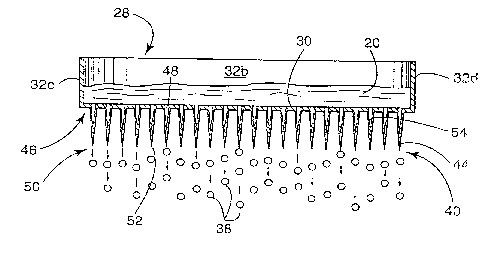
In a key aspect of the invention, the dropper
assembly 10 is formed with projections 44 that are
associated with the tray 28 (see Figure 3). More
particularly, the preferred embodiment of the invention
is designed with a separate projection 44 cooperating
with each individual orifice 42 formed in the bottom
wall 30 of the tray 28. The projections 44 preferably
extend downwardly from the bottom wall 30 of the tray
28 toward the freezing chamber 12. Each projection 44
thus has, at its first end 46, an inlet opening 48 that
is in communication with the associated orifice 42 and,
at its second end 50, an outlet opening 52.
A flow channel 54 extends the entire length
of each projection 44 from the inlet opening 48 to the
outlet opening 52. The projections 44 preferably taper
to become narrower toward its second end So. It
follows then that the inlet opening 48 has~a larger
dimension than the outlet opening S2. The narrowing of
the flow channel 54 promotes regulated accumulation of
the liquid composition 20 and thus promotes regulated
discharge of the liquid composition from the tray 28.
The design further allows a droplet 38 to be formed in
an orderly fashion until the net gravity force
overcomes the interfacial tension forces on the droplet
38 and it falls toward the freezing chamber lZ.
The flow rate of the liquid composition 20
through the flow channel 54 is a factor in the orderly
formation of droplets 38 at the second end 50 of the
projection 44. The flow rate is a function of, among
other things, the dimensions of the inlet opening 48
and the outlet opening 52. It has been determined that
uniformly sized droplets 38 form and are released from
the projection 44 when the ratio of the dimension of
the inlet opening 48 to the outlet opening 52 is in the
CA 022l6375 l997-09-24
. SEP.Z3.1997 3:26PM THMS~KDEN~HSMYR~R aY " NO.773 P.8
. ~9J2~Jlgg7 14:~6 6~62~41~99 5TCCKWELL L~ OFCS PAGE 1
W 0~61~ C PCrnUN61~2S6
14
r~nge of su~t~nti;l~ly 2; ~ to -~ubs~An~ 2 0 :1. Ir
the parti~'l ~~ pre~e~re~ e~nbodi~an~ of ~he inven~ion,
nl~ o~ln~J 4~ h~5 a dlamster o* s~ ially
0~37~ ~n~he~ nd She ou~et openins~ S2 h~s a dian~ r
~7~ eu~s~ntially 0., 031~S ~nc2~ hus, ~he dimension
ra~o o~ the par~ ular preferr~d n~ ~ is
subst~n~ially 1~
y ~a an~ projs~ ionS 44 are prefera~ly
m4de of d~able food grad~ pla~ r StAin'lP.t;s ~teel
ana ~t be formed during o~;~in~l manufa~l:ur~
Alterneltively, ~he proje~ion~ 44 m~y be la~:e~
~ conn~cted ~:o ~e ~ ~ay 28 a~c A~04iA~ced or~fi~es 4~ .
Pipe~te tips may be used a~ the projec~ion~ 44
in~gr~eel ~h the tra~ 28 in ~his ins~anee. ~he
pipe~e tipE; of ~he p~astic ~ype n~ be puro~ ee~ fr~
in~;trur~ent di6~ri~4~0Fs suoh a~ Cole~Parnler~ Inst~me~
Comp;~ny of Chica~o, I1~ ihOi~.
T}le prinoipal advan~Agea; o~ t~e in~en~ive
~Iropper a~se~l~ lo are be~t x~e:o~n$~3d by co~npa~i~;~
ZO w~ ~h the prio~ ar~ n enlarg~d illustration of w~i~h
i6 pre~:ente~ in F~ gu~ 4 . U5~2~g the prime iden~i~icr
a3 a supelr~cript ~or cc~mponents similar ~o those u~ed
in the inv~n~iv~ A~eml~ o, prior Art apparat~6~ have
a ~ray 2~ ' ~h ~ch or~ices 4a ' ~re foxmed in ~he
zs bottom surface ~0', Droplet~ 3~' ~re :~or~ed ~n~
rele~sed direc:tly ~om l:he orifices 42' ur,de~ 'che ~orce
o~ gr~y~ Thcre ~ no G~yCSI: Lun~ty ~r r~gula~ed
ul~t~ on of liquid co~ ition ~o ' and thu~
6patt:ering freguen1:~r o~c.~ p4n re~ e~se of a drople~
3~ m ~e o~ce 4~' o~ ~he tray ~ urthermore,
sor~c drople~3 38 ' r~leaE~ed ~ro~ t;h~ c-ri~ices 4;~ ' aro ~o
unst~le ~h~t ~they br~ pare into ~;m~ller drople~s,
~r~At~¦ ng ~ropletg o~ ~idcl~ rarying ~i~es ~nd ~lso
~. re~ultirlg ~n ~ur~he~ spattering. ~he ery sm3~1 bea~s
3~ di~race rrom the unitluc ~r-d ple~sing ~ppcaran~e of ~he
CA 0221637~ 1997-09-24
.; , .
WO96/298s6 PCT~S96104Z56
desirably sized beads and thus it is necessary to
eliminate them from the final product.
Furthermore, the spattering created during
droplet release and/or break-up generates minute
particles P that also fall into the freezing chamber
and form particles of frozen microbeads and/or dust
that accumulate at the bottom thereof. This creates
the need to shut the production process down to clean
out the freezing chamber 12. Furthermore, the frozen
microbeads represent waste, which obviously decreases
efficient operation and production.
Numerous benefits result from the use of the
inventive dropper assembly 10 and the method of feeding
liquid composition to a freezing chamber 12 using the
assembly. In contrast to prior art designs, the
projections 44 of the present invention promote the
regulated discharge of the liquid composition Z0 from
the tray 28 and the formation of uniformly sized
droplets 38 of liquid composition 20 that, when
delivered to the freezing chamber 12, form uniformly
sized beads 18 of frozen product. The use of the novel
dropper assembly 10 eliminates the need for any
filtering requirement, and power to operate filtering
components. In addition, the projections 44 prevent
the spattering of minute particles of liquid
composition 20 and thus prevents the formation of
frozen microbeads and/or dust that have previously
accumulated at the bottom of the freezing chamber 12.
The foregoing description of a preferred
embodiment of the invention has been presented for
purposes of illustration and description. It is not
intended to be exhaustive or to limit the invention to
the precise form disclosed. Obvious modifications or
variations are possible in light of the above
teachings. The embodiment was chosen and described to
CA 02216375 1997-09-24
. SEP.Z3.1997 3:27PM THMS/KDENVHSMYR~RSL~ NO.773 P.9
, ~9~23~199~ 14:B6 b362~41399 STaC~EUL LAW OFCS P~E 19
WV ~6~s~sc rcT~
16
pro~id~ t:he ~st illuEItr~t~ on ~ lR prin~ l e~ of t~e
in~qn~; on ~n~ pr~c~ieal aprl ic~ion to 1;~ereky
ena~lQ on~ of ordin~ry ~ 1 in ~e ~rt ~o uti lizQ the
inYentieln ~ n ~iau~ ~ont~ J.nd with vaxiou~
~o~lificat~ on~ ~3 it suited ~o 'che p~lcul~r u~e
cont;~npl~te~l. A~l such modi~ic~ions ~nd v~r~ on~;
o~-c ~ithi~ the ~:oope of th~ ~ n~n~ion a~ d~
the ~ - ~ ClAinl~ wh~n ;nt~L~3Led ~n ~ccord;~ b wlth
breadth to c~hic:h ~hey E~ $r~y, legally ~nd ~ ly
~ntitled.