Note : Les descriptions sont présentées dans la langue officielle dans laquelle elles ont été soumises.
CA 02217021 1997-09-30
Hydraulic Circuit for Hydraulic Equipment
Technical Field
The present invention relates to a hydraulic circuit for hydraulic equipment used
in various types of construction work, such as hydraulic shovels.
5 Background Art
Some hydraulic equipment for construction work is arranged to control
pressurized oil fed to a plurality of hydraulic actuators, using their corresponding control
valves. SwiLcl~ g means for such control valves include pilot-operated means, which use
pilot pressurized oil fed to control valves, and other means, for example, manual,
10 mechanical, and electrical means.
Since control equipment for such means, including operating levers, is sometimesoperated unexpectedly against the operator's will, a safety locking mech~ni~m needs to be
installed in hydraulic equipment to prevent hydraulic actuators from operating accidentally.
To form such a safety locking mech~ni.~m, conventional pilot-operated means have safety
15 valves installed in pilot oil lines between pilot pressuri_ed oil sources and pilot valves,
switching pilot pressurized oil feed to control valves. When a safety valve is closed, pilot
pressllri7~d oil is not fed to a control valve, so that it cannot be switched to their
pres.cllri7~d oil feed position. However, when the operator unlocks the safety lever in the
operator's seat, for example, the safety valve opens, thus allowing pilot pressurized oil
20 to be fed to the control valve. The other means mentioned above have mechanical locking
devices attached to the control equipment, by use of which devices the operator locks or
unlocks the control equipment.
Locking mech~ni~m~ for switching means other than pilot-operated means have
a problem of a locking device being required by the individual control equipment. What
25 is worse, operating such a locking device is troublesome because it needs to be operated
every time locking or unlocking is done. To solve these problems, the idea has been
proposed that locking devices for switching means are interlocked so that locking and
unlocking can be done using switches. Mech~ni~m~ based on the idea, however, also need
CA 02217021 1997-09-30
locking devices for their individual control equipment, which consist of many parts and
are complex in structure and costly. This is a problem which the present invention is
intended to solve.
Another problem with conventional switching means is that safety valves for
5 pilot-operated means and those for other means use different locking mech~nism~.
Disclosure of the Invention
Taking into account the foregoing, the present invention has been made to solve
the problems described above. According to a first aspect of the present invention, a
hydraulic circuit for hydraulic equipment, which circuit is arranged so that pressurized oil
10 feed to a plurality of hydraulic actuators is controlled using their corresponding control
valves, wherein there are provided an unloading oil line that leads from a pressurized oil
source, which feeds pressurized oil to said plurality of hydraulic actuators, to an oil
reservoir without passing through the control valves and an unloading oil line selector
valve that opens or closes the unloading oil line. The hydraulic circuit enables pressurized
15 oil feed to the hydraulic actuators to be stopped by opening the unloading oil line, so that
the hydraulic actuators are locked at the same time. This elimin~tes the need for
troublesome locking of individual hydraulic actuators.
According to a second aspect of the present invention, a hydraulic circuit for
hydraulic equipment, which circuit is arranged so that pressurized oil feed to a plurality
20 of hydraulic actuators is controlled using their corresponding control valves and uses both
pilot-controlled means, relying on pilot pressurized oil fed to the control valves to switch
them, and other means as valve switching means, wherein there are provided an unloading
oil line that leads from a pressurized oil source feeding pressurized oil to said hydraulic
actuators to an oil reservoir without passing through the control valves of the at least other
25 means and an unloading oil line selector valve that opens or closes the unloading oil line,
and furthermore there is provided a branch pilot oil line between a supply source of said
pilot pre~l-ri7e~ oil and a pilot valve switching pilot pre.c.sllri7e-1 oil into said control
valve, said unloading oil line selector valve is arranged to switch from open position to
closed position by feeding pilot pressurized oil through the branch pilot oil line and a pilot
CA 02217021 1997-09-30
.~ .
oil line selector valve for opening or closing said pilot oil line is placed in a pilot oil line
between said pilot pressurized oil source and a branch point for opening or closing said
pilot oil line. The hydraulic circuit enables the hydraulic actuators to be locked at the
same time as in the case of the first aspect of the present invention. Moreover, since pilot
5 pressurized oil switches the unloading oil line selector valve, only stopping pilot
pressurized oil feed causes the hydraulic actuators to be locked, and the hydraulic circuit
arrangement is simple.
According to the second aspect of the present invention again, the control valves
can be prevented from being switched to the pressurized oil feed position by ~hlltting off
10 pilot pressurized oil fed to the pilot valves and unloading oil line selector valve when the
pilot oil line selector valve is closed.
According to the first and second aspects of the present invention, a hydraulic
circuit for hydraulic equipment according to any of claims 1 through 3, wherein there are
provided an additional hydraulic actuator besides said plurality of hydraulic actuators, a
15 second pre~sllri7etl oil source that feeds pressurized oil to the additional hydraulic
actuator, and a second control valve that controls pres.~llri7Pcl oil feed to the additional
hydraulic actuator, and the urlloading oil line selector valve can be switched not only to
open and closed positions which cause the unloading oil line to open and close but to a
connection position which causes a valve path feeding to the second control valve
20 pressurized oil flowing through the oil line from the pressurized oil source for the plurality
of hydraulic actuators to the unloading oil line selector valve to open to join together
pressurized oil from said oil line and pressurized oil from the second pressurized oil
source. The unloading oil line selector valve not only opens or closes the unloading oil
line but joins together pressurized oil from one of the pressurized oil sources and
25 pressurized oil from the other. That is, the unloading oil line selector valve has two
functions used for hydraulic circuits, thus simplifying hydraulic circuit arrangement.
In the hydraulic circuit, the oil line *om the pressurized oil source for the
plurality of hydraulic actuators to the unloading oil line selector valve is formed so that
the oil line passes through a neutral control valve which does not allow pressurized oil to
30 be fed to its corresponding hydraulic actuator. This is favorable because pressurized oil
CA 02217021 1997-09-30
can be fed to the additional hydraulic actuator when pressurized oil is not fed to the
plurality oi hydraulic actuators.
Brief Description of the Drawings
Figure 1 is a side view of a hydraulic shovel.
Figure 2 is a diagram of part of a hydraulic circuit for a hydraulic shovel.
Figure 3 is a diagram of another part of the hydraulic circuit for a hydraulic
shovel.
Figure 4 is a diagram of still another part of the hydraulic circuit for a hydraulic
shovel.
Figure 5 is an enlarged view illustrating the connections of a first selector valve.
Figure 6 is an enlarged view illustrating the connections of a second selector
valve.
Best Mode for Carrying Out the Invention
Referring now to the drawings, an embodiment of the present invention is
15 described below. In the drawings, the numeral 1 intlic~tes a hydraulic shovel. The
hydraulic shovel 1 comprises crawler type lower structure 2; an upper structure 3 pivoted
over the lower structure 2 so that it rotates freely; and a work ~tt~chment 4 installed in
front of the upper ~lul-;ulure 3. The hydraulic shovel 1 also has right and left travel
motors 5R and 5L for traveling the lower structure 2; a swing motor 6 for swinging the
20 upper ~lurclule 3; and several actuators including a boom swing cylinder 9, shifting a
boom 7 from side to side; an arm cylinder 11, moving an arm 10 back and forth; a bucket
cylinder 13, moving a bucket 12 back and forth; and a blade cylinder 15, moving a blade
14 up and down. These hydraulic actuators are arranged so that they operate by means
of pressurized oil from hydraulic pumps P driven by an engine E as a power source which
25 is installed in the upper structure 3.
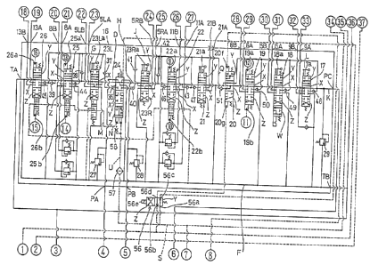
Referring now to the hydraulic circuits in Figures 2, 3, and 4, pressurized oil
feed to the hydraulic actuators above are described below. The embodiment has two
hydraulic pumps P, that is, first and second hydraulic pumps Pl and P2. These pumps
CA 02217021 1997-09-30
Pl and P2 are arranged so that pressurized oil from them is fed to the actuators through
a control valve unit 16 for controlling pressurized oil feed to the actuators.
The control valve unit 16 incorporates various valves including boom swing,
blade, swing, arm, right travel, left travel, boom, and bucket control valves 17, 18, 19,
5 22, 23R, 23L, 25, and 26, a control valve 21 for a replacement attachment (for example,
an attachment removably attached to a hydraulic shovel, such as a breaker, not shown),
first and second selector valves 20 and 24, and relief valves 27, 28, and 29. The control
valve unit also has various ports formed therein, including first and second pump ports
PA and PB connected to the first hydraulic pump PI; a third pump port PC connected to
10 the second hydraulic pump P2; first and second tank ports TA and TB connected to an oil
reservoir T; input/output ports 9A, 9B, lSA, lSB, 6A, 6B, 1 lA, 1 lB, SRA, 5RB, 5LA,
5LB, 8A, 8B, 13A, 13B connPcted to the boom swing cylinder 9, blade cylinder 15,swing motor 6, arm cylinder 11, right travel motor SR, left travel motor 5L, boom
cylinder 8, and bucket cylinder 13; and input/output ports 21A and 21B (power takeouts
lS PTO) detachably connPcte~ to a replacement attachment (the ports 21A and 21B are closed
when no replacement attachment is installed).
Using control levers, the control valves 17, 18, 19, 21, 22, 23R, 23L, 25, and
26 in the control valve unit 16 can be switched from a neutral position X, which allows
no pressurized oil to be fed from the hydraulic pumps Pl and P2 to the hydraulic20 actuators, to a press lri7P~l oil feed position Y, which allows pressurized oil to be fed to
one of the input/output ports of a corresponding hydraulic actuator, or a pressurized oil
feed position Z, which allows pressurized oil to be fed to the other (a blade control valve
18 can be placed in a blade own-weight descent position W, as well as the positions X,
Y, and Z, which does not allow pressurized oil to be fed, but the blade cylinder 15 to be
25 contracted by the own weight of the blade 14). The swing, arm, boom, and bucket
control valves 19, 22, 25, and 26 are arranged so that they are pilot-operated; that is,
feeding pilot pressurized oil from revolving, arm, boom, and bucket pilot valves 32, 33,
34, and 35 to pilot ports l9a, l9b, 22a, 22b, 25a, 25b, 26a, and 26b, formed in the
control valves 19, 22, 25, and 26, by using operating levers 30 and 31 causes the control
30 valves to switch from the neutral position X to the pressurized oil feed position Y or Z.
CA 022l702l l997-09-30
The boom swing, blade, replacement ~ hment, right travel, and left travel control
valves 17, 18, 21, 23L, and 23R are arranged so that they are m~ml~lly operated; that is,
using operating levers 17a, 18a, 21a, 23La, and 23Ra directly linked through linkages
with the control valves causes them to switch from the neutral position X to the5 pressurized oil feed position Y or Z.
As described above, the embodiment uses pilot-operated or m~ml~lly operated
control valves. The present invention, however, is not limited to control valves of these
two types and can apply to such control valves as operated mechanically or electrically.
Below is briefly described a basic hydraulic circuit formed in the control valve10 unit 16. A first pump center bypass oil line D passes through the first pump port PA and
then the second selector valve 24 and connects to the left running control valve 23L placed
downstream, which is in the pressurized oil feed position Y or Z. The oil line D also
passes through the left running control valve 23L, which is in the neutral position X, the
boom control valve 25, and the bucket control valve 26 and reaches a tank oil line F,
15 connecting to the first tank port TA or the second tank port TB.
A first pump parallel oil line G passes through the first pump port PA, the
second selector valve 24, a restrictor 36, and a check valve 37 and connects to the boom
control valve 25 and the bucket control valve 26, which are in the pressurized oil feed
position Y or Z. The oil line G is installed in parallel with the first pump center bypass
20 oil line D. Pressurized oil passing through the left rurming control valve 23L and boom
control valve 25 along the first pump center bypass oil line D flows through check valves
38 and 39 into the first pump parallel oil line G.
A second pump center bypass oil line H passes through the second pump port
PB and then the second selector valve 24 and connects to the right travel control valve
25 23R placed downstream, which is in the pressurized oil feed position Y or Z. The oil line
H also passes through the right travel control valve 23R, which is in the neutral position
X, the arm control valve 22, and the replacement attachment control valve 21 and reaches
the tank oil line F.
A second pump parallel oil line J passes tbrough the second pump port PB, the
30 second selector valve 24 at a junction described below, a restrictor 40, and a check valve
CA 02217021 1997-09-30
41 and connects to the arm control valve 22, which is in the pressurized oil feed position
Y or Z, and the replacement attachment control valve 21. The oil line J is installed in
parallel with the second pump center bypass oil line H. Pressurized oil running along the
second pump center bypass oil line H through the right travel control valve 23R and arm
S control valve 22, which are in the neutral position X, flows through check valves 42 and
43 into the second pump parallel oil line J.
A third pump center bypass oil line K passes through the third pump port PC and
connects to the boom swing control valve 17, which is in the pressurized oil feed position
Y or Z. The oil line K also passes through the boom swing control valve 17, blade
10 control valve 18, revolving control valve 19, and first selector valve, all of which are in
the neutral position X, and reaches the tank oil line F.
A third pump parallel oil line L, branching from the third center bypass oil line
K upstream of the control valves 17, 18, and 19 cormects to the blade control valve and
swing control valve 19 which are in the pressurized oil feed position Y or Z and the
15 second selector valve 20 in the neutral position X, which valve is described later. The
oil line L is installed in parallel with the third pump center bypass oil line K.
The left travel control valve 23L is arranged as described below. When in the
neutral position X, the travel control valve 23L allows pressurized oil passing through the
first pump center bypass oil line D to flow to the side of the boom control valve 25 and
20 pressurized oil passing through a fourth branch pilot oil line M, described later, to flow
to the side of the boom control valve 25 and tank oil line F. When in the pressurized oil
feed position Y or Z, on the other hand, the control valve 23L allows pressurized oil input
from the first pump center bypass oil line D to be output to the left running input/output
ports SLA and SLB and pressurized oil passing through the fourth branch pilot oil line M
25 to flow to the side of the boom control valve 25.
The boom control valve 25 is arranged as described below. When in the neutral
position X, the boom control valve 25 allows pressurized oil passing along the first pump
center bypass oil line D through the left travel control valve 23L and pilot pressurized oil
passing through the fourth branch pilot oil line M to flow to the side of the bucket control
30 valve 26. When in the pressurized oil feed position Y or Z, The boom control valve 25
CA 02217021 1997-09-30
allows pressurized oil input through a check valve 44 from the first pump parallel oil line
G to be output to the boom input/output ports 8A and 8B.
The bucket control valve 26 is arranged as described below. When in the neutral
position X, the bucket control valve 26 allows pressurized oil running along the first
5 center bypass oil line D through the boom control valve 25 to flow into the tank oil line
F and pilot pressurized oil running along the fourth branch pilot oil line M through the
left travel control valve 23L and boom control valve 25 to flow to the side of the arm
control valve 22. When in the pre~sllri7~-1 oil feed position Y or Z, on the other hand,
the bucket control valve 26 allows press lri~s~l oil input through a check valve 45 from the
10 first pump parallel oil line G to be output to the bucket input/output ports 13A and 13B.
The right travel control valve 23R is arranged as described below. When in the
neutral position X, the right travel control valve 23R allows pressurized oil passing
through the second pump center bypass oil line H to flow to the side of the arm control
valve 22. When in the pressurized oil feed position Y or Z, on the other hand, the control
15 right travel valve 23R allows pressurized oil input from the second pump center bypass
oil line H to be output to the right running input/output ports SRA and 5RB.
The arm control valve 22 is arranged as described below. When in the neutral
position X, the arm conkol valve 22 allows pressurized oil passing along the second pump
center bypass oil line H through the right travel control valve 23R to flow to the side of
20 the replacement attachment control valve 21 and pilot press~lri~ed oil running along the
fourth branch pilot oil line M through the left travel control valve 23L, boom control
valve 25, and bucket control valve 26 to flow into the tank oil line F. When in the
pressurized oil feed position Y or Z, on the other hand, the arm control valve 22 allows
pressurized oil input through a check valve 46 from the second pump parallel oil line J
25 to be output to the arm input/output ports 1 lA and llB.
The replacement attachment control valve 21 is arranged as described below.
When in the neutral position X, the control valve 21 allows pre~sllri7e~1 oil running along
the second pump center bypass oil line H through the right travel control valve 23R and
arm control valve 22 to flow into the tank oil line F. When in the pressurized oil feed
30 position Y or Z, on the other hand, the control valve 21 allows pressurized oil input
CA 02217021 1997-09-30
through a check valve 47 from the second pump parallel line J to be output to the
replacement attachment input/output ports 21A and 21B.
The boom swing control valve 17 is arranged as described below. When in the
neutral position X, the boom swing control valve 17 allows pressurized oil passing
5 through the third pump center bypass oil line K to flow to the side of the blade control
valve 18. When in the pressurized oil feed position Y or Z, on the other hand, the control
boom swing valve 17 allows pressurized oil input through a check valve 48 from the third
pump center bypass oil line K to be output to the boom swing input/output ports 9A and
9B.
The blade control valve 18 is arranged as described below. When in the neutral
position X or blade own-weight descent position W, the blade control valve 18 allows
pressurized oil running along the third pump center bypass oil line K through the boom
swing control valve 17 to flow to the side of the swing control valve 19. When in the
precsl-ri7~1 oil feed position Y or Z, on the other hand, the control valve 17 allows
lS pressurized oil input through a check valve 49 from the third pump parallel oil line L to
be output to the blade input/output ports 15A and 15B.
The swing control valve 19 is arranged as described below. When in the neutral
position X, the swing control valve 19 allows pre~sllri~ oil running along the third pump
center bypass oil line K through the boom swing control valve 17 and the blade control
20 valve 18 to flow to the side of the first selector valve 20. When in the pressurized oil
feed position Y or Z, on the other hand, the control valve 19 allows pressurized oil input
through a check valve S0 from the third pump parallel oil line L to be output to the
revolving input/output ports 6A and 6B.
The first selector valve 20 is pilot-operated so that it switches between three
25 positions according to the condition of pl~s~ul~d oil feed to the first and second pilot
ports 20f and 20g. A first port 20a connects to the third pump parallel oil line L; a
second port 20b, the pump center bypass oil line K; a third port 20c, the tank oil line F;
and a fourth port 20d, the tank oil line F. A fifth port 20e connects to a connection oil
line Q joining an oil line that leads through a check valve 51 to the replacement
30 ~tt~cllment control valve 21 in the second pump parallel oil line J.
CA 02217021 1997-09-30
The first selector valve 20 is arranged so that the valve path from the first port
20a to the third port 20c and those from the second port 20b to the fourth and fifth ports
20d and 20e open when the selector valve is in the neutral position X which does not
allow pressurized oil to be fed to the first and second pilot ports 20f and 20g. This
S arrangement causes pre~ ri7~ oil fed from the second hydraulic pump P2 through the
third pump port PC to be unloaded through the third pump parallel oil line L into the tank
oil line F.
As describe later, when in the single-flow position Y which allows pilot
pressurized oil to be fed to the first pilot port 20f, the first selector valve 20 is arranged
10 so that the first and third ports 20a and 20c close and that the valve path from the second
port 20b to the fourth and fifth ports 20d and 20e open. This arrangement prevents
pressurized oil flowing through the third pump parallel oil line L from being unloaded into
the tank oil line F (that is, the unloading oil line closes) and allows pressurized oil running
along the third pump center bypass oil line K through the boom swing control valve 17,
15 blade control valve 18, and swing control valve 19, all of which are in the neutral position
X, to be unloaded into the tank oil line F.
When in the connection position Z that allows pilot pressurized oil is fed to the
second pilot port 20g, the first selector valve 20 is arranged so that the first, third, and
fourth ports 20a, 20c, and 20d open and that the valve path from the second port 20b to
20 the fifth port 20e opens. This arrangement prevents pressurized oil passing through the
third pump parallel oil line L from being unloaded into the tank oil line F as described
above and allows pressurized oil rurming along the third pump center bypass oil line K
through the boom swing control valve 17, blade control valve 18, and swing control valve
19, all of which are in the neutral position X, to flow through the connection oil line Q
25 to the side of the replacement attachment control valve 21.
The second selector valve 24 is pilot-operated so that it switches between threepositions according to the condition of pressurized oil feed to the first and second pilots
24h and 24i. A first port 24a connects to the first pump port PA; a second port 24b, the
first pump center bypass oil line D; a third port 24c, the first pump parallel oil line G;
30 a fourth port 24d, the second pump port PB; a fifth port 24e, the second pump center
CA 02217021 1997-09-30
11
bypass oil line H; a sixth port 24f, the tank oil line F; and a seventh port 24g, the second
pump parallel oil line J.
The second selector valve 24 is arranged so that the third and seventh ports 24cand 24g close and that the valve paths from the first and fourth ports 24a and 24d to the
5 second, fifth, and sixth ports 24b, 24e, and 24f open when the selector valve is in the
neutral position X which does not allow pilot pressurized oil to act on the first and second
pilots 24h and 24i. This arrangement causes pressurized oil fed from the first and second
pump ports PA and PB to be unloaded into the tank oil line F.
As described later, when pilot pressurized oil acts on the first pilot 24 only but
10 does not on the second pilot 24i, the second selector valve 24 is placed in the single-flow
position Y. When in the single-flow position Y, the second selector valve is arranged so
that the third, sixth, and seventh ports 24c, 24f, and 24g close and that the valve path
from the first port 24a to the second port 24b and that from the fourth port 24d to the fifth
port 24e open. This arrangement causes pressurized oil fed from the first pump port PA
15 to flow into the first pump center bypass oil line D and plc;s~ulized oil fed from the
second pump port PB to flow into the second pump center bypass oil line H.
When the pilot pressurized oil acts on the first and second pilots 24h and 24i,
the second selector valve is placed in the connection position Z. When in the connection
position, the second selector valve is arranged so that the sixth port closes and that the
20 valve paths from the first and fourth ports 20a and 20d to the second, third, fifth, and
seventh ports 20b, 20c, 20e, and 20g open. Restrictors 52 and 53 are placed in the valve
paths from the first and fourth ports 20a and 20d to the second and fifth ports 20b and
20e. The arrangement above causes pressurized oil from the first pump port PA and
pressurized oil from the second pump port PB to join together at the second selector valve
25 24 and flow into the first pump center bypass oil line D, first pump parallel oil line G,
second pump center bypass oil line H, and second pump parallel oil line J.
A pressurized oil feed circuit is described below. The embodiment is arranged
to use some of pressurized oil fed from the second hydraulic pump P2. Pilot pressurized
oil from the second hydraulic pump P2 is fed through a safety valve 54 and a pilot filter
30 55, both of which will be described later, to the swing, arm, boom, bucket control valves
CA 02217021 1997-09-30
12
32, 33, 34, and 35 and then from these valves to the pilot ports l9a, l9b, 22a, 22b, 25a,
25b, 26a, and 26b of the swing, arm, boom, and bucket control valves 19, 22, 25, and
26.
A first branch pilot oil line S, leading to an electromagnetic selector valve 56,
5 described later, is formed so that the line branches from the pilot oil line R rur~ning from
the pilot filter 55 to the pilot valves 32, 33, 34, and 35. A second branch pilot oil line
U, leading through the filter 57 to the first pilot 24h of the second selector valve 24, is
formed so that the line branches from the middle of the first branch pilot oil line S. A
third branch pilot oil line N, leading through a restrictor 58 to the second pilot 24i, is
10 formed so that the line branches from the oil line between the filter 57 and the first pilot
24h in the second branch pilot oil line U. The fourth branch pilot oil line M is formed
so that the line branches from the oil line between the restrictor 58 and the second pilot
24i in the third branch pilot oil line N.
The safety valve 54 is a two position selector valve switched by operating a
15 safety lever 54d installed at the operator's seat. The fist port 54a connects to the second
hydraulic pump P2; the second port 54b, the oil reservoir T; and the third port 54c, the
pilot filter 55.
When the safety lever 54d is in the locked position, the safety valve 54 is alsoin the locked position which causes the first port 54a to close and the valve path from the
20 third port 54c to the second port 54b to open. When in the locked position, the safety
valve shuts off pilot p~ l oil from the second hydraulic pump P2, thus preventing
pilot pressurized oil from being fed to the pilot oil line R and the first, second, third, and
fourth branch pilot oil lines S, U, N, and M.
When the safety lever 54d is in the unlocked position, the safety valve 54 is also
in the unlocked position which causes the second port 54b to close and the valve path
from the first port 54a to the third port 54c to open. When the safety valve is in the
unlocked position, pilot pre~sllri7~1 oil from the second hydraulic pump P2 is fed to the
pilot oii line R and the first, second, third, and fourth branch pilot oil lines S, U, N, and
M.
The electromagnetic selector valve 56 is a two position selector valve. A first
CA 02217021 1997-09-30
~ ,
13
port 56a connects to the first branch pilot oil line S; a second port 56b, the oil reservoir
T; and a third port 56c, the first pilot port 20f of the first selector valve 20; and a fourth
port 56d, the second pilot port 20g of the first selector valve 20.
The solenoid 56e of the electromagnetic selector valve 56 electrically connects
S to the operating lever 21a for the replacement attachment control valve 21 (or to a control
unit comected to the replacement attachment control valve 21 or to the replacement
attachment control valve 21 itself). The electromagnetic selector valve 56 is arranged so
that it is placed in the single-flow position Y which causes the valve path from the first
port 56a to the third port 56c and that from the fourth port 56c to the second port 56b to
10 open when the control lever 21a is not in use; that is, the replacement ~7tt~chment control
valve 21 is in the neutral position X. When the electrom,7gnl tic selector valve is in the
single-flow position Y, pilot pressurized oil from the first branch pilot oil line S is fed to
the first pilot port 20f of the first selector valve 20. Thus the first selector valve 20 is
placed in the single-flow position Y as described above.
The electromagnetic selector valve 56 is also arranged so that the valve is placed
in the connection position Z which causes the valve path from the first port 56a to the
fourth port 56d and that from the third port 56c to the second port 56b to open when the
operating lever 21a is in use; that is, the replacement attachment control valve 21 is in the
press7lri7ec7. oil feed position Y or Z. When the electromagnetic selector valve is in the
20 connection position, pilot pressurized Oi71 from the first branch pilot oil line S is fed to the
second pilot port 20g of the first selector valve 20. Thus the first selector valve 20 is
placed in the connection position Y as described above.
Below is described pilot pressurized oil acting on the pilots 24h and 24i of thesecond selector valve 24. As described above, pilot pressurized oil is not fed to the
25 second, third, or fourth branch pilot oil line when the safety valve 54 is in the locked
position. This, in turn, means that pilot pressurized oil acts neither on the first pilot 24h
nor on the second pilot 24i, so that the second selector valve 24 is placed in the neutral
position X as described above.
The selector valve 54 switching to the unlocked position causes pilot pressurized
30 oil to be fed to the second, tllird, and fourth branch pilot oil lines U, N, and M. When
CA 02217021 1997-09-30
14
pilot pressurized oil is fed to the branch pilot oil lines and the fourth branch pilot oil line
M is open, that is, the boom control valve 25, bucket control valve 26, and arm control
valve 22 are in the neutral position X, pilot pressurized oil acts on the first pilot 24h due
to the throttling effect of the restrictor 58 downstream of the first pilot, but does not on
5 the second pilot 24i. Thus the second selector valve 24 is placed in the single-flow
position X as described above.
When pilot pressllriz.od oil is fed to the second, third, and fourth branch pilot oil
lines U, N, and M and the fourth branch pilot oil line M is closed, that is, when the left
travel control valve 23L is in the pressurized oil feed position Y or Z and at least one of
10 the boom, bucket, and arm control valves 25, 26, and 22 is in the pressurized oil feed
position Y or Z, pilot pressurized oil acts on both first and second pilots 24h and 24i, so
that the second selector valve 24 is placed in the connection position Z as described above.
For the arrangements described above, when the hydraulic actuators installed in
the hydraulic shovel 1 need to be locked, for example, the operator leaves the operator's
15 seat, he places the safety valve 54 in the locked position, using the safety lever 54d.
When the safety valve is in the locked position, no pilot pressurized oil is fed to the pilot
oil line R or the first, second, third, and fourth branch pilot oil lines S, U, N, and M, as
described above. Thus pilot pressurized oil is not fed to the pilot port l9a, l9b, 22a, 22b,
25a, 25b, 26a, and 26b even though the pilot valves 32, 33, 34, and 35 are switched using
20 the operating levers 30 and 31. This leads the swing, arm, boom, and bucket control
valves 19, 22, 25, and 26, which are pilot-operated, not to switch from the neutral
position X to the pressurized oil feed position Y or Z, so that the swing motor 6, arm
cylinder 11, boom cylinder 9, or bucket cylinder 13 does not operate.
When pilot pressurized oil is not fed to the pilot oil lines, it is fed neigher to the
25 pilot ports 20f and 20g of the first selector valve 20 nor to the pilots 24h and 24i of the
second selector valve 24, so that the first and second selector valves 20 and 24 are both
placed in the neutral position X.
When the first and second selector valves are in the neutral position X,
pressurized oil fed from the second hydraulic pump P2 through the third pump port PC
30 is unloaded through the first selector valve 20 into the tank oil line F, as described above.
CA 022l702l l997-09-30
Pressurized oil fed from the first hydraulic pump Pl through the first and second pump
ports PA and PB is also unloaded through the second selector valve 24 into the tank oil
line F. Thus pilot pre~sllri7P~l oil is not fed to the boom swing cylinder 9, blade cylinder
15, replacement attachment, or right and left travel motors 5R and 5L even though the
5 manual control valves 17, 18, 21, 23L, and 23R are switched to the pressurized oil feed
position Y or Z using the boom swing, blade, replacement attachment, and right and left
travel control levers 17a, 18a, 21a, 23La, and 23Ra. This means that the hydraulic
actuators 9, 15, 5L and 5R do not operate.
To unlock a hydraulic actuator, that is, use a operating lever for operating its10 corresponding hydraulic actuator, the safety valve 54 is switched to the unlocked position
using the safety lever 54d. When the safety valve is in the unlocked position, pilot
pressurized oil is fed to the pilot oil line R and the first, second, third, and fourth branch
pilot oil lines S, U, N, and M. That is, using the operating levers 30 and 31 causes the
pilot valves 32, 33, 34, and 35 to switch from one position to another. Thus pilot
15 pressurized oil is fed to the pilot ports l9a, l9b, 22a, 22b, 25a, 25b, 26a, and 26b, so that
the swing, arm, boom, and bucket control valves, which are pilot-operated, switch from
the neutral position X to the pressurized oil feed position Y or Z.
When pressurized oil is fed to the pilot oil lines, it is also fed to the pilot ports
20f and 20g of the first selector valve 20 and the pilots 24h and 24i of the second selector
20 valve 24. When the replacement attachment operating lever 21a is not in use, pilot
pressurized oil is fed from the first branch pilot oil line S through the electromagnetic
selector valve 56, which is in the single-flow position Y, to the first pilot port 20f, so that
the first selector valve 20 is placed in the single-flow position Y. When the first selector
valve is in the single-flow position, pressurized oil fed from the second hydraulic pump
P2 through the third pump port PC is further fed through the control valves 17, 18, and
19, which have been switched to the pressllri7e~i oil feed position Y or Z using the boom
swing, blade, and swing operating levers 17a, 18a, and 30, to hydraulic actuators, that is,
the boom swing cylinder 9, blade cylinder 15, and swing motor 6. This means that using
the operating levers allows the hydraulic actuators to operate.
Using the operating lever 21a for a replacement attachment attached to the
CA 022l702l l997-09-30
16
hydraulic shovel 1 causes the electrom~gn~tic selector valve 56 to switch to the connection
position Z, thus feeding pilot pressurized oil from the first branch pilot oil line S to the
second pilot port 20g of the first selector valve 20. As a result, the first selector valve
20 switches to the connection position Z. When at least one of the boom swing, blade,
5 and swing operating levers 17a, 18a, and 30 is in use, with the first selector valve 20 in
the connection position Z, pressurized oil is fed from the third pump center bypass oil line
K and third pump parallel oil line L through the control valves 17, 18, and 19 to the boom
swing cylinder 9, blade cylinder 15, and swing motor 6, so that the hydraulic actuators
9, 15, and 6 can operate. When none of the boom swing, blade, and swing operating
10 levers 17a, 18a, and 30 is in use, pres.sllri7~1 oil flowing through the third pump center
bypass oil line K flows into t_e second pump parallel oil line J connected to the
replacement attachment control valve 21, through the control valves 17, 18, and 19, which
are in the neutral position X; the first selector valve 20, which is in the connection
position Z; and the connection oil line Q. This causes pressurized oil to be fed from not
15 only the second pump parallel oil line J but the third center bypass oil line K to the
replacement ~tt~hment.
When pressurized oil is fed to the pilot oil lines, with none of the boom, bucket,
and arm operating levers 30 and 31 in use, pilot pressurized oil acts only on the first pilot
24h, as described above, so that the second selector valve 24 is placed in the single-flow
20 position Y. When the second selector valve is in the single-flow position Y, pressurized
oil fed from the first hydraulic pump Pl through the first pump port PA is further fed
from the first pump center bypass oil line D through the left travel control valve 23L,
which has been switched to the pressurized oil feed position Y or Z using the operating
lever 23La, to the left travel motor 5L. Pressllri7e~1 oil fed from the first hydraulic pump
25 Pl through the second pump port PB, on the other hand, is further fed from the second
pump center bypass oil line H and second pump parallel oil line J through the right travel
and replacement attachment control valves 23R and 21, which have been switched to the
pre~llri7ed oil feed position Y or Z using the operating levers 23Ra and 21a, to the right
and left travel motors 5R and 5L and replacement attachment hydraulic actuator. This,
30 in turn, means that using the operating levers allows the hydraulic actuators to operate.
CA 02217021 1997-09-30
Pressllri7.?~1 oil from the first pump port PA is fed to the left running motor SL, and
pressurized oil from the second pump port PB is fed to the right running motor 5R and
replacement ~tt~chment hydraulic actuator; that is, pressllri7ecl oil from the two dirr~lellt
ports PA and PB are fed to their corresponding special hydraulic actuators.
S When the left travel operating lever 23La and at least one of the boom, bucket,
and arm operating levers 31 and 30 are in use, pilot pressurized oil acts on both first and
second pilots 24h and 24i, thus placing the second selector valve 24 in the connection
position Z. When the second selector valve is in the connection position Z, pressurized
oil from the first pump port PA and pressurized oil from the second pump port PB join
10 together in the second selector valve 24, flow into the pump center bypass oil line D, first
pump parallel oil line G, second pump bypass oil line H, and second pump parallel oil line
J, and feed through the control valves 21, 22, 23L, 23R, 25, and 26, which have been
switched to the pressllri7ecl oil feed position Y or Z using the replacement attachment,
arm, right and left travel, boom, and bucket operating levers 21a, 30, 23La, 23Ra, and
lS 31, into hydraulic actuators, that is, the replacement attachment hydraulic actuator, arm
cylinder 11, right and left travel motors SR and SL, boom cylinder 8, and bucket cylinder
13. This, in turn, means that using the operating levers allows the hydraulic a~;Lu~tol~, to
operate. After joining together in the second selector valve 24, pressurized oil from the
first pump port PA and pressurized oil from the second pump port PB are fed to the
20 actuators as required.
As described above, in the embodiment, only switching the safety valve 54
between locked and unlocked positions allows a plurality of actuators to be locked and
unlocked at the same time no matter whether the control valves controlling pressurized oil
feed to the actuators are pilot-operated or operated by other means. This increases
25 hydraulic actuator operability. Moreover, the present invention elimin~tes the need for
locking devices for conventional control valves that are not pilot-operated, thus helping
reduce hydraulic circuit cost.
In addition, the first and second selector valves 20 and 24 can not only switch
between feeding pressllri7ecl oil from the hydraulic pumps Pl and P2 to the hydraulic
30 actuators and unloading the oil to the side of the oil reservoir T but join together a pump
CA 022l702l l997-09-30
18
oil line from one of the hydraulic pumps and a pump oil line from the other. This means
that one selector valve has two functions, thus reducing the number of parts in a hydraulic
circuit and cutting hydraulic circuit cost.
In Figures 1, 2, and 3, the items with the same circled numbers are connected
5 together.
Industrial Availability
Taken together, the present invention is industrially available in terms of the
following advantages.
The arrangement described in claim 1 enables hydraulic actuators to be locked
10 at a time by stopping pressurized oil feed to the actuators by opening unloading oil lines,
which advantage elimin~tes the need for troublesome locking of individual hydraulic
actuators.
The arrangement described in claim 2 also enables hydraulic actuators to be
locked at a time as in the case of the arrangement of claim 1. Since pilot pressurized oil
15 switches the unloading oil line selector valve, only stopping pilot pressurized oil feed
causes the actuators to be locked, and the hydraulic circuit is simple.
The arrangement described in claim 2, when rearranged as described in claim
3, prevents the control valves from being switched to the pressurized oil feed position and
the unloading oil line selector valve from being switched to the closed position by closing
20 the pilot oil line selector valves, so that a plurality of hydraulic actuators can be locked
at a time.
The arrangements described in claims 1 through 3, when rearranged as described
in claim 4, enable the unloading oil line selector valve not only to open or close the
unloading oil line but to join together pressurized oil from one of the pressurized oil
25 sources and pressurized oil from the other. Thus the unloading oil line selector switch has
two functions in the hydraulic circuit, thus helping simplify hydraulic circuit arrangement.
The arrangement described in 4, when rearranged as described in claim 5,
favorably enables the additional hydraulic actuator besides the plurality of hydraulic
actuators to be fed with pressurized oil when they are not fed with pressurized oil.