Note : Les descriptions sont présentées dans la langue officielle dans laquelle elles ont été soumises.
CA 02220209 2003-07-02
-1-
TORQUE SPLITTING DEVICE USING HYDRAULIC CLUTCHES
TECHNICAL FIELD
The present invention relates to a torque splitting device for changing
the torque distribution ratio to right and left axles or front and rear axles
of a
vehicle depending on the operating condition of the vehicle.
BACKGROUND OF THE INVENTION
The applicant has previously proposed, for instance in the United
States patent no. 5,692,987, a torque splitting device which, provided in
parallel with a conventional differential device, controls the simulated
rolling
resistance to each of the right and left or front and rear axles and boosts
the
rotational speed of the axle encountering a lower rolling resistance. Thereby,
the torque distribution ratio to the right and left axles can be positively
changed depending on the steering wheel steering angle and the vehicle
speed to the end of improving the steering performance of the vehicle.
As illustrated in Figure 10, this previously proposed torque splitting
device T comprises an oil pressure pump 32 producing an output pressure
that depends on the vehicle speed, a regulator Re for adjusting the output
pressure to a prescribed level, a pair of wet hydraulic multi-disk clutches Ca
and Cd for producing simulated rolling resistances, a pressure regulating
valve 30 consisting of a linear solenoid valve for determining a torque
distribution ratio for the right and left (or front and rear) wheels according
to
the turning radius or the road resistance, and controlling the engagement
forces of the clutches Ca and Cd so as to achieve a desired torque
distribution ratio by adjusting the oil pressure for each of the clutches to a
target value, an electronic control unit 29 for computing the target oil
pressures, and controlling the electric current for the pressure regulating
valve
30, and a planetary gear mechanism P which is connected to the wet
hydraulic multi-disk clutches Ca and Cd and actually distributes the torque.
The output of the engine E forwarded to the torque splitting device T via the
transmission TM can be thus appropriately distributed to the right and left
(or
front and rear) axles 5L and 5R depending on the
CA 02220209 1997-11-OS
- 2 -
operating condition of the vehicle.
The operating response of such a clutch is affected by the viscosity
of the actuating oil, and tends to drop under a low temperature condition
because of an increase in viscosity. Because the clutch is typically
disengaged by removal of the actuating oil from the clutch cylinder, the
response delay is particularly significant when disengaging the clutch
under a low temperature condition. The reduction in the response of the
clutch due to an increase in the flow resistance to the actuating oil means
that the difference in rotational speed between the right and left wheels
to may remain even after the steering wheel is brought back to the neutral
position. This is not desirable because it causes discomfort to the vehicle
operator.
Also, because the output of the oil pressure pump depends on the
vehicle speed, the oil pressure pump may not be able to produce a
1~ sufficient oil pressure to appropriately operate the wet hydraulic multi-
disk
clutch in a low speed range. The volumetric efficiency of the oil pressure
pump, which typically consists of a gear pump or a cam pump using a
trochoidal or other piston element, is known to be affected by the viscosity
or the temperature of the oil. When the oil temperature is high, and the
2o viscosity of the oil is therefore low, the volumetric efficiency of the oil
tends to drop. Therefore, for instance when a certain oil pressure target
value is supplied to the pressure control valve so as to create a certain
difference in the driving force between the right and left wheels to
accommodate a turning maneuver, the oil pressure pump may not be able
2s to produce the require oil pressure if the rotational speed of the engine
is
low and/or the oil temperature is high. Under such a condition, when the
rotational speed of the oil pressure pump is accelerated from a low speed
range involving an insufficient output pressure of the pump, it is possible
for the wet hydraulic multi-disk clutch to abruptly engage as soon as the
30 output pressure of the pump reaches a prescribed value. This means a
discontinuity in the torque distribution control, and is not desirable again
as it causes a discomfort to the vehicle operator.
BRIEF SUMMARY OF THE INVENTION
In view of such problems of the prior art, a primary object of the
3s present invention is to provide a torque splitting device using at least
one
hydraulic clutch which can maintain a satisfactory control action even ,
CA 02220209 1997-11-OS
-3-
when the property of the oil is not suitable for a normal operation of the
clutch.
A second object of the present invention is to provide a torque
splitting device which can operate satisfactorily even when the oil
temperature is excessively low.
A third object of the present invention is to provide a torque
splitting device which can operate satisfactorily even when the rotational
speed of the oil pump for providing an oil pressure for the clutch is so low
that the oil pressure for the clutch is inadequate.
to A fourth object of the present invention is to provide a torque
splitting device which is economical and can operate satisfactorily
virtually under all conditions.
A fifth object of the present invention is to provide a torque
splitting device which can ensure a smooth control action without regard to
the condition of the actuating oil.
According to the present invention, these and other objects can be
accomplished by providing a torque splitting device for distributing an
input torque applied to an input member to a pair of output members at an
adjustable distribution ratio, comprising : a torque splitting mechanism
2o including at least one hydraulically actuated clutch for controlling a
torque
distribution ratio to the two output members; an oil circuit for supplying
actuating oil to the clutch including a regulating valve for controlling a
pressure of the actuating oil supplied to the clutch; a sensor for detecting
an actuating property of the actuating oil; and a control unit for
25 controlling the torque distribution ratio via the regulating valve
according
to a prescribed control schedule; the control unit being adapted to modify
the control schedule according to an output from the sensor. Typically,
the torque distribution ratio is achieved by changing a rotational speed of
at least one of the output members.
so One of the important actuating properties of the oil is its
temperature. When the temperature is low, and the oil therefore
encounters a relatively high flow resistance particularly as it flow out of
the clutch, a certain delay may be produced in the response of the system
when disengaging the clutch. In that case, a target value for the pressure
35 Of the actuating oil supplied to the clutch may be reduced from a normal
value so that the response delay becomes less pronounced. This is useful,
CA 02220209 1997-11-OS
- 4 -
for instance ,when the torque splitting device is applied for distributing
engine output torque to right and left wheels to improve the turning
behavior of the vehicle. When the steering angle is brought back to the
neutral position after making a turning maneuver, if the normal control
schedule is applied, the difference in rotational speed between the right'
and left wheels may remain even after the steering wheel is brought back
to the neutral position. Therefore, by controlling the pressure supplied to
the clutch when the oil temperature is low, it is possible to avoid any
problems associated with the delay in expelling oil from the hydraulic
to clutch.
For instance, a torque limiting coefficient by which the target value
of the actuating oil pressure is modified may be selected so as to be
substantially proportional to the oil temperature when the oil temperature
is below a prescribed value, and becomes substantially equal to one when
the oil temperature is equal to or higher than the prescribed value.
Another important property of the actuating oil is its pressure.
The pressure for the actuating the clutch is normally produced from a
pressure source typically consisting of a pump which is actuated at a
variable speed, for instance corresponding to a vehicle speed, and may not
2o be adequate for properly engaging the clutch particularly when the speed
by which the pump is actuated is too low. This typically occurs when a
vehicle equipped with a torque splitting device is travelling at a low speed.
In such a case, the pressure for the clutch may be inadequate and the clutch
may not be as tightly engaged as intended. When the pump or the vehicle
25 is accelerated from such a state, the resulting increase in the pressure
output of the pump may cause an abrupt engagement of the clutch, and
may cause some discomfort to the operator. To avoid this from occurring,
a target value for the pressure of the actuating oil supplied to the clutch
may be reduced from a normal value when the actuating speed of the pump
so is lower than a normal value. This becomes particularly pronounced
when the oil temperature is high and the viscosity of the oil is low because
the pump typically consisting of a gear pump or a cam pump loses its
volumetric efficiency under such a condition.
According to a preferred embodiment of the present invention, a
35 torque limiting coefficient by which the target value of the actuating oil
pressure is modified is selected so as to be substantially proportional to the
CA 02220209 1997-11-OS
- 5 -
. vehicle speed when the vehicle speed is below a prescribed value, and
becomes substantially equal to one when the vehicle speed is equal to or
higher than the prescribed value, the prescribed value of the vehicle speed
being increased from, a standard value when the oil temperature is higher
than a normal value.
BRIEF DESCRIPTION OF THE DRAWINGS
Now the present invention is described in the following with
reference to the appended drawings, in which:
Figure 1 is a longitudinal sectional view of a torque splitting device
to for distributing an input torque to right and left axles of a vehicle
embodying the present invention;
Figure 2 is a longitudinal sectional view of a differential device
which is connected to the torque splitting device of Figure 1;
Figure 3 is a skeleton diagram of a power transmission system of a
15 front engine, front drive vehicle .;
Figure 4 is a view similar to Figure 3 illustrating the control action
during a right turn. ;
Figure 5 is a view similar to Figure 3 illustrating the control action
during a left turn;
20 Figure 6 is a block diagram of the first embodiment of the present
invention showing the generation of the torque limiting coefficient, and
application of the coefficient (EN2) to the target value for the torque
distribution ratio (TOBJ);
Figure 7 is a flow chart showing the control action of the first
2~ embodiment of the present invention;
Figure 8 is a block diagram of the second embodiment of the
present invention showing the generation of the torque limiting coefficient,
and application of the coefficient (EN1) to the target value for the torque
distribution ratio (TOBJ);
so Figure 9 is a flow chart showing the control action of the second
embodiment of the present invention; and
Figure 10 is a block diagram showing the overall structure of a
previously proposed torque splitting device to which the present invention
is applied.
3s DETAILED DESCRIPTION OF THE PREFERRED EMBODIMENTS
First of all, the torque splitting device to which the present
CA 02220209 1997-11-OS
-6-
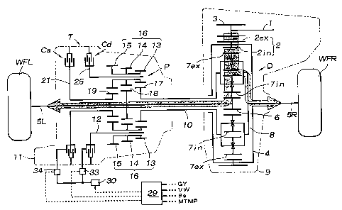
invention is applied is described with reference to Figures 1 and 2. This
torque splitting device T is connected to an output shaft 1 of a transmission
to which the engine output is transmitted, via a differential device D which
is illustrated in Figure 2.
s ~ The differential device D consists of a double pinion type planetary
gear mechanism, and comprises a driven member 2 which includes an
external teeth gear 2ex meshing with an output gear 3 provided on an axial
end of the output shaft 1 of the transmission, and an internal teeth gear tin
formed integrally with the external teeth gear 2ex, differential casing
to halves 4L and 4R which are joined together by threaded bolts interposing
the driven member 2 between them, right and left output shafts 5L and 5R
which are rotatably passed through central holes of the differential casing
halves 4L and 4R, respectively, a sun gear 6 which is spline coupled to an
axial end of the left output shaft 5L, outer pinions 7ex which each mesh
15 with the internal teeth gear tin of the driven member 2 and rotate around
both itself and the sun gear 6, inner pinions 7in (see Figure 3; the inner
pinions 7in do not appear in Figure 1) which each mesh with the outer
pinions 7ex and the sun gear 6 and rotate around both itself and the sun
gear 6, and right and left planetary carriers 8L and 8R which rotatably
2o support the inner and outer pinions 7in and 7ex. Central parts of the right
and left differential casings 4L and 4R are supported by a transmission
housing 9 for instance by roller bearings. The right planetary carrier 8R
pivotally supports the sun gear 6 via a needle bearing, and is spline
coupled to an axial end of the right output shaft 5R. The left planetary
25 carrier 8L surrounds the left output shaft 5L, and is spline coupled to the
right end of a sleeve 10 passed through the central hole of the left
differential casing 4L.
In this differential device D, the driven member 2 serves as an
input element, and the sun gear 6 which serves as one of two output
so elements, is connected to the left front wheel WFL via the left output
shaft
5L while the right planetary carrier 8R which serves as the other output
element is connected to the right front wheel WFR via the right output
shaft 5R. A drive shaft equipped with a known isokinetic coupling is
interposed between the left output shaft 5L and the left front wheel WFL,
3s and between the right output shaft 5R and the right front wheel WFR.
The torque splitting device T consists of a planetary gear
CA 02220209 1997-11-OS
_ 7 _
mechanism P, and clutches Ca and Cd for acceleration and deceleration
each consisting of a wet hydraulic mufti-plate clutch.
The planetary gear mechanism P of the torque splitting device T
comprises a planetary carrier 12 pivotally supported by a casing 11 so as to
surround the left output shaft SL, a plurality (for instance four) of triple
pinion members 16 which each integrally combine a first pinion 13, a
second pinion 14 and a third pinion 15, and pivotally supported along a
circle concentric to the center of the planetary carrier, a first sun gear 17
. pivotally supported around the left output shaft SL and meshes with the
first pinion 13, a second sun gear 18 which is spline coupled to the outer
circumference of the left output shaft 5L at a point immediately left of the
first sun gear 17, and a third sun gear 19 which is integral with an inner
plate retaining member 21 of the acceleration clutch Ca and meshes with
the third pinion 15. The inner plate retaining member 21 is pivotally
is supported around the left output shaft SL.
The first sun gear 17 is spline coupled to the left end of the sleeve
which is in turn spline coupled to the left planetary carrier 8L of the .
differential device D so as to integrally rotate with the planetary carriers
8L and 8R and the right output shaft SR of the differential device D.
The acceleration clutch Ca couples inner plates 22, which are
axially slidably engaged by the inner plate retaining member 21 pivotally
mounted on the left output shaft SL, with outer plates 23, which are axially
slidably engaged by an inner surface of the casing 11, with the thrust force
of an annular hydraulic piston 24, and performs the function of arresting
2s the rotation of the third sun gear 19 which is integral with the inner
plate
retaining member 21.
The deceleration clutch Cd couples inner plates 26, which are
axially slidably engaged by an inner plate retaining member 25 formed in
the planetary carrier 12, with outer plates 27, which are axially slidably
so engaged by an inner surface of the casing 11, with the thrust force of an
annular hydraulic piston 28, and performs the function of arresting the
rotation of the triple pinion members 16, which are pivotally supported by
the planetary carrier 12, around the sun gears.
The engagement forces of the acceleration and deceleration
~ clutches Ca and Cd are controlled by the oil pressure supplied thereto from
a gear pump 32, driven by a spur gear 31 spline coupled to the left output
CA 02220209 1997-11-OS
_ $ _
shaft 5L, via an oil pressure circuit including a pressure regulating valve
30. The pressure regulating valve 30 is controlled by an electronic
control unit 29 receiving a vehicle speed VW and a steering angle 8s as
data.
Now the operation of this device is described in the following with
reference to Figures 3 to 5.
When the vehicle is traveling straight ahead, the deceleration and
acceleration clutches Cd and Ca are both disengaged. As a result, the
planetary carrier 12 and the third sun gear 19 of the torque splitting device
1o T are both allowed to move freely, and the left output shaft 5L, the right
output shaft 5R, the planetary carrier 8 of the differential device D, and the
planetary carrier 12 of the torque splitting device T all move in a body.
. As indicated by the shaded arrow in Figure 3, the output torque of the
engine is evenly distributed to the right and left front wheels WFL and
15 WFR via the differential device D.
When the vehicle is turning right, as shown in Figure 4, the
deceleration clutch Cd is engaged so that the planetary carrier 12 is joined
with the casing 11, and is thereby kept stationary. Because the left front
wheel WFL which is integral with the left output shaft 5L (or the planetary
20 carrier 8L of the differential device D) is coupled with the right front
wheel WFR which is integral with the right output shaft 5R (or the
planetary carrier 8R of the differential device D) via the meshing between
the second sun gear 18 and the second pinion 14, and the meshing between
the first pinion 13 and the first sun gear 17, the rotational speed NL of the
2~ left front wheel WFL is increased in speed over the rotational speed NR of
the right front wheel WFR.
NL/NR = (Z4 / Z3) (Z1 / Z2) ... (Equation 1)
so where Z1 : number of teeth of the first sun gear 17
Z2 : number of teeth of the first pinion 13
Z3 : number of teeth of the second sun gear 18
Z4 : number of teeth of the second pinion 14
As described above, when the rotational speed NL of the left front
~ wheel WFL is increased in speed over the rotational speed NR of the right
front wheel WFR, as indicated by the shaded arrow in Figure 4, a part of
CA 02220209 1997-11-OS
_g.
the torque distributed to the right front wheel WFR or the inner wheel from
the differential device D is transmitted to the left front wheel WFL or the
outer wheel.
When the planetary carrier 12 of the torque splitting device T is
reduced in speed by partly engaging the deceleration clutch Cd instead of
totally preventing the motion of the planetary carrier 12, the rotational
speed NL of the left front wheel WFL is increased in speed over the
rotational speed NR of the right front wheel WFR by a corresponding
amount so that it is possible to change the amount of torque transmission
to from the right front wheel WFR or the inner wheel to the left front wheel
WFL or the outer wheel at will.
When the vehicle is turning left, as shown in Figure 5, the
acceleration clutch Ca is engaged so that the third sun gear 19 which is
integral with the inner plate retaining member 21 of the acceleration clutch
is Ca is kept stationary. As a result, the triple pinion members 16 rotate
around the center of the sun gears via the third pinion 15 meshing with the
third sun gear 19, and the rotational speed of the planetary carrier 12 is
increased over the rotational speed NL of the left front wheel WFL
according to the following relationship.
NL/NR = [1- (ZS / Z6) (Z2 / Z1)] / [1- (ZS / Z6) (Z4 / Z3)]
... (Equation 2)
where ZS : number of teeth of the third sun gear 19
2s Z6 : number of teeth of the third pinion 15
As described above, when the rotational speed NR of the right front
wheel WFR is increased in speed over the rotational speed NL of the left
front wheel WFL, as indicated by the shaded arrow in Figure 5, a part of
the torque distributed to the left front wheel WFL or the inner wheel from
so the differential device D is transmitted to the right front wheel WFR or
the
outer wheel. In this case also, it is possible to change the amount of
torque transmission from the left front wheel WFL to the right front wheel
WFR at will by changing the engagement force of the acceleration clutch
Ca.
35 According to the above described torque splitting device T, the
operating response of the two clutches Ca and Cd depends on the viscosity
CA 02220209 1997-11-OS
- 10 -
of the actuating oil, and, in particular, the response of the clutches at the
time of disengagement tends to drop under a low oil temperature condition.
Therefore, when the steering wheel is brought back to the neutral position
from a turning maneuver which involves a difference in the torques of the
s right and left wheels, the disengagement of the clutch tends to be delayed,
thereby causing a discomfort to the vehicle operator.
Therefore, according to a first embodiment of the present invention,
when computing the torque distribution ratio, the electronic control unit 29
takes into account a torque limiting coefficient which changes from O to
1.0 depending on the oil temperature so that the oil pressure target value
for each of the clutches may be compensated for by multiplying the torque
limiting coefficient to the basic torque distribution ratio.
Now the operation of the electronic control unit 29 according to the
first embodiment of the present invention is described in the following
~s with reference to Figures 6 and 7.
Torque distribution ratio computing means 41 computes a torque
distribution ratio (T1) from a turning amount (KG) and an axle drive
torque (XGF) by using a mathematical function f (step 1). The turning
amount KG is given by the following formula.
KG = YG + f (8s x VW) ... (Equation 3)
where YG : lateral acceleration
8s : steering angle
VW : vehicle speed
A torque limiting coefficient (EN2) corresponding to the current oil
temperature (MTMP) is obtained from a reference vehicle speed map 43
which is given by such a linear function which produces the value of 0
when the oil temperature is - 30 °C and the value of 1.0 when the oil ,
3o temperature is equal to or higher than 30 °C (step 2).
Then, a compensated torque distribution ratio (TOB~ which is
suited for the current operating condition of the vehicle is obtained by
multiplying the torque limiting coefficient (EN2) to the torque distribution
ratio (T1) in step 3. The current value which is required to be given to
the pressure regulating valve 30 to achieve this oil pressure is computed by
target current value computing means 44 (step 4) so that the oil pressure
CA 02220209 1997-11-OS
- 11 -
which is to be supplied to each of the clutches Ca and Cd is controlled by
the pressure regulating valve 30 and the solenoid on/off valve 33 and 34
(Figure 3).
Thus, according to the first embodiment of the present invention,
when computing a torque distribution ratio, a torque limiting coefficient
(EN2) which changes from 0 to 1.0 depending on the oil temperature is
defined so that the control may be carried out by taking into account the
sluggishness of the actuating oil when the oil is not warmed up.
Therefore, the smoothness of the control can be ensured without being
affected by the oil temperature.
Now the operation of the electronic control unit 29 according to a
second embodiment of the present invention is described in the following
with reference to Figures 8 and 9. The second embodiment may comprise
substantially identical hardware to that of the first embodiment so that
is reference should be made to Figures 1 to 5 as required for the
understanding of the second embodiment. Also, in the description of the
second embodiment, the parts corresponding to the first embodiment are
denoted with like numerals.
According to the hardware of the above described torque splitting
2o device T, the output of the gear pump 32 which controls the engagement
forces of the two clutches Ca and Cd depends on the speed of actuating the
gear pump 32. The actuating speed of the gear pump 32 in this case is
proportional to the vehicle speed because the pump 32 is actuated by the
output shaft SL. Therefore, the oil pressure which is required for
25 producing a prescribed engagement force may not be available in a low
vehicle speed range. Also, the rotational speed versus flow rate property
of a gear pump is normally significantly dependent on the oil temperature
so that the rated oil pressure may not be produced from the pump when the
oil temperature is excessively high and the viscosity of the oil is low.
3o Therefore, when an oil pressure target value is supplied to the pressure
regulating valve 30 so as to produce a required difference in the drive force
between the right and left wheels of the vehicle as it makes a turn at a
relatively low speed, the pressure available for engaging the clutch may. be
not be adequate, and the intended torque distribution may not be achieved.
35 When the vehicle is accelerated under such a condition, the available
pressure may abruptly increase so that the clutch may abruptly engage as
CA 02220209 1997-11-OS
- 12 -
soon as the output pressure of the pump increases beyond a certain level,
thereby causing a discomfort to the vehicle operator.
Therefore, according to the second embodiment of the present
invention, when computing the torque distribution ratio, the electronic
control unit 29 takes into account a torque limiting coefficient which
changes from 0 to 1.0 depending on the vehicle speed so that the oil
pressure target value for each of the clutches may be compensated for by
multiplying the torque limiting coefficient to the basic torque distribution
ratio. Furthermore, the vehicle speed at which this coefficient reaches the
to value of 1.0 is made dependent on the oil temperature.
Torque distribution ratio computing means 41 computes a torque
distribution ratio (T1) from a turning amount (KG) and an axle drive
torque (XGF) by using a mathematical function f (step 1). The turning
amount KG is given by Equation 3 which was given above.
A reference vehicle speed (VSTL) corresponding to the current oil
temperature (MTMP) is obtained from a reference vehicle speed map 42,
and a torque limiting coefficient (EN1) corresponding to the current
vehicle speed (VW) is obtained from a torque limiting coefficient map 43
which gives the value of 1.0 at the reference vehicle speed (the coefficient
2o being given as a linear equation such that the coefficient is 0 when the
vehicle speed (VV~ is 0, and 1.0 when the vehicle speed is equal to or
greater than the prescribed value (VSTL) given by the reference vehicle
speed map 42) (step 2). The prescribed value (VSTL) of the vehicle
speed that is to be obtained from the reference vehicle speed map 42 is
2s selected to be somewhat greater than the actual vehicle speed at which the
pump is capable of producing the prescribed oil pressure.
Then, a compensated torque distribution ratio (TOBJ) which is
suited for the current operating condition of the vehicle is obtained by
multiplying the torque limiting coefficient (EN1) to the torque distribution
30 , ratio (T1) in step 3. The current value which is required to be given to
the pressure regulating valve 30 to achieve this oil pressure is computed by
target current value computing means 44 (step 4) so that the oil pressure
which is to be supplied to each of the clutches Ca and Cd is controlled by
the pressure regulating valve 30 and the solenoid on/off valve 33 and 34.
35 The rotational speed difference that will be produced when the
clutches Ca and Cd are fully engaged should be selected at a value which
CA 02220209 1997-11-OS
- 13 -
is smaller than the rotational speed difference between the right and left
axles that will be produced at the time of a maximum steering angle. '
In case of a pump actuated by an electric motor, an accumulator for
storing oil pressure becomes necessary to increase the effective pump
capacity without increasing the size of the motor, and it is detrimental to a
compact design. A pump which is actuated by a vehicle axle and is
therefore dependent on vehicle speed allows a compact design, as
compared with a motor driven pump, owing to the elimination of the need
for an electric motor, and also contributes to an improvement in reliability
owing to the absence of any electric wiring.
Thus, according to the second embodiment of the present invention,
when computing a torque distribution ratio, a torque limiting coefficient
which changes from 0 to 1.0 depending on the vehicle speed is defined,
and the vehicle speed at which this coefficient reaches the value of 1.0 is
is made dependent on the oil temperature so that the control may be carried
out within the range of available oil pressure when the vehicle is traveling
at a low speed particularly under a high oil temperature condition.
Therefore, because the control can be carried out in a continuous manner
even when the vehicle is accelerating from a low speed, the smoothness of
2o the control can be ensured. Also, because the control amount is limited in
an extremely low speed range, in case of an extremely tight turn which
may cause the rotational speed difference between the inner and outer
wheels in the torque splitting control device to exceed an upper limit, the
control action is limited in such a manner that the turning movement of the
25 vehicle is prevented from being adversely interfered by the torque
splitting
control.
Although the present invention has been described in terms of
preferred embodiments thereof, it is obvious to a person skilled in the art
that various alterations and modifications are possible without departing
3o from the scope of the present invention which is set forth in the appended
claims. For instance, in the above described embodiments, the present
invention was applied to right and left torque splitting devices, but, as one
can readily appreciate, is equally applicable to front and rear torque
splitting devices.