Sélection de la langue

Search

Sommaire du brevet 2222872 

Énoncé de désistement de responsabilité concernant l'information provenant de tiers

Une partie des informations de ce site Web a été fournie par des sources externes. Le gouvernement du Canada n'assume aucune responsabilité concernant la précision, l'actualité ou la fiabilité des informations fournies par les sources externes. Les utilisateurs qui désirent employer cette information devraient consulter directement la source des informations. Le contenu fourni par les sources externes n'est pas assujetti aux exigences sur les langues officielles, la protection des renseignements personnels et l'accessibilité.

Disponibilité de l'Abrégé et des Revendications

L'apparition de différences dans le texte et l'image des Revendications et de l'Abrégé dépend du moment auquel le document est publié. Les textes des Revendications et de l'Abrégé sont affichés :

  • lorsque la demande peut être examinée par le public;
  • lorsque le brevet est émis (délivrance).
(12) Demande de brevet: (11) CA 2222872
(54) Titre français: MECANISME ANTI-CLIQUETIS POUR CARTOUCHE DE DISQUE
(54) Titre anglais: DISK CARTRIDGE ANTI-RATTLE MECHANISM
Statut: Réputée abandonnée et au-delà du délai pour le rétablissement - en attente de la réponse à l’avis de communication rejetée
Données bibliographiques
(51) Classification internationale des brevets (CIB):
  • G11B 23/02 (2006.01)
  • G11B 23/03 (2006.01)
(72) Inventeurs :
  • SCHICK, BRIAN R. (Etats-Unis d'Amérique)
  • BRACKEN, ALLEN T. (Etats-Unis d'Amérique)
  • RICH, EDWARD L. (Etats-Unis d'Amérique)
  • SUMNER, WAYNE A. (Etats-Unis d'Amérique)
(73) Titulaires :
  • IOMEGA CORPORATION
(71) Demandeurs :
  • IOMEGA CORPORATION (Etats-Unis d'Amérique)
(74) Agent: CASSAN MACLEAN
(74) Co-agent:
(45) Délivré:
(86) Date de dépôt PCT: 1996-06-06
(87) Mise à la disponibilité du public: 1996-12-19
Licence disponible: S.O.
Cédé au domaine public: S.O.
(25) Langue des documents déposés: Anglais

Traité de coopération en matière de brevets (PCT): Oui
(86) Numéro de la demande PCT: PCT/US1996/009438
(87) Numéro de publication internationale PCT: US1996009438
(85) Entrée nationale: 1997-11-28

(30) Données de priorité de la demande:
Numéro de la demande Pays / territoire Date
08/477,764 (Etats-Unis d'Amérique) 1995-06-07
08/550,818 (Etats-Unis d'Amérique) 1995-10-31

Abrégés

Abrégé français

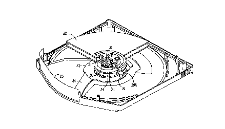
Cartouche de mécanisme d'entraînement de disques magnétiques pourvue d'un mécanisme de serrage actionné lorsque l'orifice d'accès (23) de la cartouche est fermée, quand la cartouche est enlevée de l'entraînement. Ledit accès recouvre l'ouverture par laquelle des têtes de lecture-écriture accèdent à la cartouche. Quand la cartouche est enlevée de l'entraînement, le mécanisme (26) de la présente invention serre le disque enregistreur contre le boîtier de la cartouche pour empêcher le cliquetis, qui sans cela pourrait endommager le disque d'enregistrement.


Abrégé anglais


A cartridge for a magnetic disk drive has a clamping mechanism which is
actuated as the door (23) to the cartridge is closed when the cartridge is
removed from the drive. The door covers the openings through which the
cartridge is accessed by read/write heads. When the cartridge is removed from
the drive, the mechanism (26) of the present invention clamps the recording
disk against the cartridge shell to prevent rattle, which might otherwise
damage the recording disk.

Revendications

Note : Les revendications sont présentées dans la langue officielle dans laquelle elles ont été soumises.


- 7 -
WHAT IS CLAIMED IS:
1. (Amended) A cartridge for a drive in which read/write heads
read/record data on a recording medium comprising:
a shell having a front, a back and two sides between substantially
flat, planar surfaces;
said recording medium being in said shell;
said shell having an opening in the front thereof for access by
said read/write heads to said recording medium;
a door covering said opening when said cartridge is removed from said
drive;
a cam rotatable on the same axis as said recording medium, said cam
having a surface which extends axially as a function of the circumference of said cam
when said cam is rotated as said door is opened and closed, a translating cam follower
which is moved axially by said cam to clamp said medium against one planar surface
of said shell as said door is closed and to free said medium for rotation as said cam is
rotated to open said door;
a hub on which said recording medium is mounted, said cam follower
applying an axial force to said hub to clamp said medium against a planar wall of said
shell;
a return spring positioned co-axially with said hub, said return spring
applying bias to said hub to return it after it has been translated by said cam follower;
said return spring urging said hub away from said planar surface as said door is moved
to the open position and a cavity at the center of said hub, said cam, said cam follower
and said spring being in said cavity.
2. (canceled under Article 19)
3. (canceled under Article 19))
4. (canceled)
5. (Amended) The cartridge recited in claim 1 wherein said door has
a stroke between the open and the closed position thereof wherein said cam is
connected to said door by an actuating wire providing a spring coupling which allows
for over-travel at both ends of the stroke of said door.

- 8 -
6. (Amended) The actuator recited in claim 5 wherein said spring
coupling wire is attached to said door front at a point, wherein said door slides in
tracks, and wherein said spring coupling provides tolerance for relative changes in the
distance between said clamping means and said point at which said spring coupling
wire is between to said sliding door as said door travels through its stroke.
7. (canceled)
8. (canceled)
9. (canceled)
10. (canceled)
11. (Amended) The cartridge recited in claim 1 wherein said cam is
connected to said door by a member rotatable about the axis of said recording medium.
12. The cartridge recited in claim 11 wherein said member has an
arm extending radially toward said door, the terminal end of said arm being connected
to said door.
13. The cartridge recited in claim 12 and further comprising:
a wire connecting the terminal end of said arm to said door, said
wire being disposed in an opening in the terminal end of said arm, said wire
telescoping into and out of said opening as said door opens and closes.
14. (canceled)
15. (Amended) The cartridge recited in claim 1 further comprising:
a protrusion on said member axially opposite of said arm; and
an arcuate path for said spring, said spring having a bent end,
said bent end traveling in said arcuate path as said door moves from the open to the
closed position.
16. The cartridge recited in claim 15 further comprising:
a notch at the end of said arcuate path, said bent end of said
spring traveling into said notch to provide the force to close said door through the last
portion of travel of said door to its closed position.
17. The cartridge recited in claim 15 further comprising:
a cover for said arcuate path, said spring traveling in the covered
arcuate path as said door moves between the open and the closed position.

- 9 -
18. (Amended) A cartridge for a drive in which read/write heads
read/record data on a recording medium comprising:
a shell;
said recording medium in said shell;
said shell having an opening for access by said read/write heads to said
recording medium;
a door covering said opening when said cartridge is removed from said
drive; and
a cam rotatable on the same axis as said recording medium, said
cam having a surface which extends axially as a function of the circumference of said
cam when said cam is rotated as said door is opened and closed,
a translating cam follower which is moved axially by said cam to
clamp said medium against a planar surface of said shell as said door is closed and to
free said medium for rotation as said cam is rotated to open said door;
said cam being connected to said door to rotate said cam as said
door is moved between the open and the closed positions;
a member rotatable about the axis of said recording medium, said
cam being connected to said door by said member, said member having an arm
extending radially toward said door, the terminal end of said arm being connected to
said door; and
a wire connecting the terminal end of said arm to said door, said
wire being disposed in an opening in the terminal end of said arm, said wire
telescoping into and out of said opening as said door opens and closes.
19. (Amended) A cartridge for a drive in which read/write heads
read/record data on a recording medium comprising:
a shell;
said recording medium being in said shell;
said shell having an opening for access by said read/write heads to said
recording medium;
a door covering said opening when said cartridge is removed from said
drive;

- 9/1 -
clamping means actuated as said door is opened and closed for
restraining said medium when said door is closed and freeing said medium for rotation
when said door is open, said clamping means comprising:
a cam rotatable on the same axis as said recording
medium, said cam having a surface which extends axially
as a function of the circumference of said cam;
a translating cam follower which is moved axially by
said cam to clamp said medium against one wall of said
shell;
a hub on which said recording medium is mounted,
said cam follower applying an axial force to said hub
to clamp said medium against said wall of said shell;
and
a return spring positioned coaxially with said
hub, said return spring applying bias to said hub to
return it after it has been translated by said cam
follower.
20. The cartridge recited in claim 19 wherein said surface of said
cam extends axially toward said wall of said cartridge as a function of the
circumference of said cam, said cam urging said hub and attached disk against said
wall when said door is in the closed position, said return spring urging said hub away
from said wall as said door is moved to the open position.

Description

Note : Les descriptions sont présentées dans la langue officielle dans laquelle elles ont été soumises.


'. CA 02222872 1997-11-28
- PcT~ 96~ 09~3~
oi ~ ) i J~N ~99~
,
CAM MECHANISM TO CLAMP MAGNETIC DISK
AGAINST CARTRIDGE .~,T
RELATED APPL~CATION
This application is a continll~tion-in-part of copending U.S. application
Serial No. 08/477,764 filed June 7, 1995 entitled "Disk Cartridge Anti-Rattle
Mech~ni~m" by Brian Schick.
BACKGROUND OF THE INVENTION
This invention relates to data storage drives and more particularly, to a
removable cartridge for magnetic disk drives.
l~n~tic disk drives which write and read digital data from flexible ~
m~gnf-ti~ disks have been ~el~iv~ly used. "Floppy disk drives" have been
extensively used for small, so-called microco~ ul~,. systems, for word-processing
applications and the like. The flexible disk cartridge includes a relatively thin, flexible
jacket which is inserted into the floppy disk drive.
Rigid disk drives, such as the IBM 3350, usually have a fixed rigid
m~gn~ti~ media. The m~gn~tic heads do not contact the m~gnPtir surface, but ride on
a thin film of air. Recall~e of this, and other f~alures, these disk drives are capable of
extremely precise and high speed operation. This type of disk drive is commonly
referred to as a "Winchester" drive. Rigid disks enclosed in a rigid, removable
cartridge, or shell have also been used. U.S. Patent 4,864,452-Thompson et al is an
example of such a drive.
"Bernoulli" disk drives having p~,rollllallce characteristics similar to that
of Winchester drives, but with removable cartridges, have been developed. A flexible
m~gn~ti~ disk is enclosed in a rigid box which is normally completely closed. U.S.
2 5 Patent 4,400,748-Bauck, et al and related patents to the common assignee show such

CA 02222872 1997-11-28
WO 96/41344 PCTAUS96/09438
-- 2 --
drives using Bernoulli stabilized flexible disks. U.S. Patent No. 4,901,173-Jones et al
and related patents to the common ~Csi~nPe~ show improvements which relate to so-
called "half height" drives.
The cartridges for these drives have a door which closes the cartridge
when it is removed from the drive. This ~levtnL~ debris from cont~min~ting the
m~ntotir recording mPflillm when the cartridge is not in the drive. When the cartridge
is inserted into the drive, this door slides to an open position to provide access for the
m~gnPtit~ recording heads to engage the recording m.o~linm
When the cartridge is removed from the drive, it is often subject to
0 rough h~n~lling. During h~n-lling, physical contact of the disk with the shell may
damage the disk, particularly if the disk and cartridge shell are subject to excessive
"rattling".
It is an object of the present invention to provide a device which clamps
the disk to the cartridge shell when the cartridge is removed from the drive to ~r~vt;l~L
1~ rattling of the cartridge.
SUMMARY OF THE D~VENTION
In accordance with the present invention, a clamping mPch~nicm in a
data storage cartridge is ~ct~l~t~d when the cartridge is removed from the drive. The
mP~h~n;~lll restrains the recording medium to prevent rattling.
The clamping m~ch~nicm is driven by the motion of the sliding door.
When the door is closed (cartridge out of drive) the mPch~nicm expands and ~ laills
the media from rattling inside the cartridge during h~n-1ling. When the door is opened
(cartridge inserted in the drive) the mechanism co,lL,acLY. such that it is free of the hub
and the media is free to rotate.
The mPçh~nicm is ~tt~chf cl to the sliding door by means of an ~ctn~ting
wire which provides a spring coupling to allow for m~ch~nicm over travel at both ends
of the sliding stroke as well as compliance to account for relative changes in the
~lict~n~e between the m~çh~ni.cm and sliding door attachment point as the door travels
through its stroke. In a ~l~re~r~d embodiment, a member rotatable about the axis of
3 o the recording mPdillm has an arm connPcted to the door and ~tt~chPs the sliding door
to the mech~nicm A wire in an opening in the terminal end of the arm telescopes into
and out of the opening as the door travels through its stroke.
-

CA 02222872 1997-11-28
W O 96/41344 PCTAUS96/09438 - 3 -
The clarnping ~ c~ ll includes a rotating cam which rotates in the
same axis as the media, a tT~n~l~ting cam follower, a return spring, and an ~ g
wire, or arm, which co~ ecL~ the l~llalillg cam to the motion of the sliding cartridge
~ door. rhe m~ch~ni~m is ~tt~ d to the cartridge top shell half. It is sihl~t~l in the
cavity formed inside the media hub. The mP~h~nicm has two states; locked and
unlocked. In the locked state the tr~n~l~tin~ cam follower applies a force against the
media hub effectively trapping the hub against the cartridge bottom shell. This force is
sufficient to prevent the media from rattling against the cartridge shell halves when out
of the drive. In the unlocked state the tr~n~l~tin~ cam does not contact the hub thus
allowing the media to spin freely.
The foregoing and other objects, features and advantages of the
invention will be better understood from the following more ~let~ile~l description and
appended claims.
SHQRT DESCRIPIION OF T~: DR~WINGS
Fig. 1 shows a top view of the cartridge of the present invention;
Fig. 2 is a front view of the cartridge;
Fig. 3 is an isometric view of the cartridge with the top shell removed;
Fig. 4 is a section on the lines A-A of Fig. 3;
Fig. 5 is a top view of the spindle motor;
2 0 Fig. 5A is a section on the line A-A of Fig. 5 showing the cartridge in
place on the motor;
Fig. 6 is broken-away isometric view of the cartridge with the door
closed;
Fig. 6A is a view similar to Fig. 6 with the door open;
Fig. 7 is a side view of the cam/cam follower assembly with the
cartridge door open;
Fig. 8 is a top view of Fig. 7;
Fig. 8A is a section on the line A-A of Fig. 8;
Fig. 9 is a side view of the cam/cam follower assembly with the
3 o cartridge door in the open position;
Fig. 10 is a top view of the assembly of Fig. 9;
Fig. 10B is a section on the line B-B of Fig. 10;

CA 02222872 1997-11-28 PC~ 96 1 ~9 ~ 8
IAN ~97
-- 4 --
Fig. 11 is an isometric view of the cam/cam follower assembly with the
cartridge in the open position;
Fig. llA is an isometric view of the section on the line A-A of Fig. 8;
Fig. 12 is an isometric view of the cam/cam follower assembly with the
cartridge door in the open position; and
Fig. 12B is an isometric view of the section on the line B-B in Fig. 10;
Fig. 13 is a broken away perspective view of a ~r~ft;.l~d embodiment of
the invention with the door in the closed position;
Fig. 14 is a cross-section of the cartridge of Fig. 13;
0 Fig. 15 is a broken-away perspective view of the cartridge of the
preferred embodiment with the door in the open position;
Fig. 16 is a cross-section of the cartridge of Fig. 15; and
Fig. 17 is a top-plan view of the cartridge with the top shell and disks
removed.
DESCRIPTION OF THE PREFERRED EMBODIMENT
Figs. 1-4 show a cartridge having two half shells 11 and 12 joined
together at 13. The cartridge has a front 14, a back 15 and two sides 16 and 17
between substantially flat, planar surfaces 18 and 19. An opening 20 in the front of
the cartridge provides access by the read/write heads to the recording disks 22, 22A.
J 2 o A flexible door 23 covers the opening when the cartridge is removed from the drive.
In accordance with the present invention, a clamping mech~ni~m is
açt~l~t~l as the door 23 is opened and closed. This m~çh~ni~m includes a rotating cam
24 which is rotatable on the same axis as the disks 22, 22A. The cam 24 has a suRace
25 which extends axially as a function of the cil.;ulllfe~ ce of the cam. Tr~n~l~ting
cam follower 26 (Fig. 6) is moved axially by the surface 25 as the cam 24 rotates.
This axial movement clamps the disk 22 against the bottom half of the shell 11 in the
position shown in Fig. 4.
As shown in Fig. 3, the rotating cam 24 is conn~-cte~l to the door 23 by
the ~ct~ ing wire 27. ~tll~tin~ wire 27 provides a spring coupling which allows for
3 0 over-travel at both ends of the stroke of the door 23. Spring 27 also provides for
relative changes in the ~ t~n~e between the cam 24 and the point 28 at which the

~ CA 02222872 1997-11-28
PG~ ; 9~/0~4~'
1~~.3~ 0 ~ JAN 1997
-- 5 --
~ctll~ting wire 27 is ~tt~(~h~o~l to the door 23. This flict~nre varies as the door travels
through its stroke.
Recording disks 22 and 22A are mounted on a hub 29 (Figs. 4 and SA).
A spacer 29A separates disks 22 and 22A. The cam follower 26 applies an axial force
to the hub 29 to clamp the recording disk 22 against the bottom wall 11 of the shell.
A ret~ining spring 30 is positioned co-axially with the hub 29. The
ret~ining spring 30 applies torsion to the hub 29 to return it to the position shown in
Fig. 3 after it has been tr~n~l~t~-~ by the cam follower 26. A co~ r~ssion spring 31
applies bias to the cam follower 26 to return it, a spring 31, which is concentric with,
o but outside of, the spring 30, provides return force for the cam follower 26 to bring it
into its open position. The springs 30 and 31 are both shown in Fig. llA. The
cartridge has a cavity at the center thereof in which the clamping mechanism of the
present invention is positioned. A hub cap 32 retains the springs in this cavity.
Figs. 13-17 show a pler~llc;d embodiment of the invention in which the
connection between the clamping mech~ m and the door is a member 33 which is
rotatable about the axis of the disks. Rotatable member 33 has an arm 34 extending
radially toward the door 23. The terminal end of arm 34 is connt?cted to the door by
the wire 35. (Figs. 16 and 17). Wire 35 is disposed in an opening 36 in the arm.The wire telescopes into and out of the opening 36 as the door travels through its
- -~ 20 stroke. This accoIIunodates the V~ g radial ~ t~n~e to the door throughout its
stroke.
A protrusion 37 on the arm has a spring 38 which provides the closing
force needed to close the door through the last portion of its travel. The spring 38 has
a bent end 39 which travels in the arcuate path 40. The arcuate path has a notch 41 at
2 5 the closing end thereof. As the bent end 39 travels along arcuate path 40, it drops into
the notch 41 at the closing end of the door stroke. This provides the extra force
n~cess~ry to close the door.
Arcuate path 40 is a depression in the face of the cartridge. This
depression has a cover 42 so that the spring 38, and its bent end 39 travel in a closed
3 0 path.

CA 02222872 1997-11-28
W O 96/41344 PCTAUS96/09438
-- 6 --
Various mofiifir~ti~n~ may be made to the p~ d embo-limtont The
appended claims are, lh~ fol~, int~ to cover all such mol1ifir~tions within the true
spirit and scope of the invention.

Dessin représentatif
Une figure unique qui représente un dessin illustrant l'invention.
États administratifs

2024-08-01 : Dans le cadre de la transition vers les Brevets de nouvelle génération (BNG), la base de données sur les brevets canadiens (BDBC) contient désormais un Historique d'événement plus détaillé, qui reproduit le Journal des événements de notre nouvelle solution interne.

Veuillez noter que les événements débutant par « Inactive : » se réfèrent à des événements qui ne sont plus utilisés dans notre nouvelle solution interne.

Pour une meilleure compréhension de l'état de la demande ou brevet qui figure sur cette page, la rubrique Mise en garde , et les descriptions de Brevet , Historique d'événement , Taxes périodiques et Historique des paiements devraient être consultées.

Historique d'événement

Description Date
Inactive : CIB de MCD 2006-03-12
Demande non rétablie avant l'échéance 2002-06-06
Le délai pour l'annulation est expiré 2002-06-06
Réputée abandonnée - omission de répondre à un avis sur les taxes pour le maintien en état 2001-06-06
Inactive : CIB en 1re position 1998-03-16
Inactive : CIB attribuée 1998-03-16
Symbole de classement modifié 1998-03-16
Lettre envoyée 1998-02-26
Inactive : Notice - Entrée phase nat. - Pas de RE 1998-02-26
Demande reçue - PCT 1998-02-24
Demande publiée (accessible au public) 1996-12-19

Historique d'abandonnement

Date d'abandonnement Raison Date de rétablissement
2001-06-06

Taxes périodiques

Le dernier paiement a été reçu le 2000-06-06

Avis : Si le paiement en totalité n'a pas été reçu au plus tard à la date indiquée, une taxe supplémentaire peut être imposée, soit une des taxes suivantes :

  • taxe de rétablissement ;
  • taxe pour paiement en souffrance ; ou
  • taxe additionnelle pour le renversement d'une péremption réputée.

Les taxes sur les brevets sont ajustées au 1er janvier de chaque année. Les montants ci-dessus sont les montants actuels s'ils sont reçus au plus tard le 31 décembre de l'année en cours.
Veuillez vous référer à la page web des taxes sur les brevets de l'OPIC pour voir tous les montants actuels des taxes.

Historique des taxes

Type de taxes Anniversaire Échéance Date payée
Taxe nationale de base - générale 1997-11-28
Enregistrement d'un document 1997-11-28
TM (demande, 2e anniv.) - générale 02 1998-06-08 1997-11-28
TM (demande, 3e anniv.) - générale 03 1999-06-07 1999-04-27
TM (demande, 4e anniv.) - générale 04 2000-06-06 2000-06-06
Titulaires au dossier

Les titulaires actuels et antérieures au dossier sont affichés en ordre alphabétique.

Titulaires actuels au dossier
IOMEGA CORPORATION
Titulaires antérieures au dossier
ALLEN T. BRACKEN
BRIAN R. SCHICK
EDWARD L. RICH
WAYNE A. SUMNER
Les propriétaires antérieurs qui ne figurent pas dans la liste des « Propriétaires au dossier » apparaîtront dans d'autres documents au dossier.
Documents

Pour visionner les fichiers sélectionnés, entrer le code reCAPTCHA :


Pour visualiser une image, cliquer sur un lien dans la colonne description du document (Temporairement non-disponible). Pour télécharger l'image (les images), cliquer l'une ou plusieurs cases à cocher dans la première colonne et ensuite cliquer sur le bouton "Télécharger sélection en format PDF (archive Zip)" ou le bouton "Télécharger sélection (en un fichier PDF fusionné)".

Liste des documents de brevet publiés et non publiés sur la BDBC .

Si vous avez des difficultés à accéder au contenu, veuillez communiquer avec le Centre de services à la clientèle au 1-866-997-1936, ou envoyer un courriel au Centre de service à la clientèle de l'OPIC.

({010=Tous les documents, 020=Au moment du dépôt, 030=Au moment de la mise à la disponibilité du public, 040=À la délivrance, 050=Examen, 060=Correspondance reçue, 070=Divers, 080=Correspondance envoyée, 090=Paiement})


Description du
Document 
Date
(aaaa-mm-jj) 
Nombre de pages   Taille de l'image (Ko) 
Abrégé 1997-11-27 1 50
Description 1997-11-27 6 247
Dessins 1997-11-27 9 250
Revendications 1997-11-27 4 163
Dessin représentatif 1998-03-18 1 14
Avis d'entree dans la phase nationale 1998-02-25 1 193
Courtoisie - Certificat d'enregistrement (document(s) connexe(s)) 1998-02-25 1 118
Courtoisie - Lettre d'abandon (taxe de maintien en état) 2001-07-03 1 182
PCT 1997-11-27 39 1 340
Taxes 2000-06-05 1 42