Note : Les descriptions sont présentées dans la langue officielle dans laquelle elles ont été soumises.
CA 022233~9 1997-12-02
APPARATUS FOR PLACEMENT OF DENTAL FILLINGS
Field of the Invention
The present invention is directed to an apparatus for placement of fillings and, in
particular, an apparatus for placement of light curable dental fillings.
5 Background of the Invention
Over the past two decades, the dental profession has been urged to provide its clients
with natural looking fillings for posterior teeth. Composite resins have been used to
provide these natural looking fillings. Composite resins, when cured, have a natural
10 tooth colour, can be placed in one appointment and are free of the toxin mercury.
Before placement, composite resins have a soft putty-like consistency and are generally
non-compactable. Fillings formed of composite resin are cured by application of a
concentrated source of light. To place a composite resin filling, a matrix is used. A
matrix is a device which wraps around a prepared tooth area. It acts as a mold and
15 limits the spread of filling materials beyond desired borders. This mold conforms ideally
to the original anatomy of the interproximal tooth structure. Matrices are generally
formed from stainless steel or plastic and can be circumferential or sectional.
Circumferential matrices fit around the entire circumference of the tooth whereas
sectional matrices fit only in one interproximal area of the tooth. Matrices are secured
20 in place by use of wedges and/or clamps. Wedges are triangular in cross section and
taper along their length. They are placed between the matrix and the adjacent tooth in
order to seal the matrix against the base of the prepared tooth structure. Wedges are
CA 022233~9 1997-12-02
generally made of wood or plastic.
The placement of composite resin fllings in the interproximal area has been found to
be very problematic. Since the resin is non-compactable, it is very difficult to create a
firm contact point between the newly placed filling and the adjacent tooth. The contact
5 point is the point at which the crown of one tooth contacts, or nearly contacts, the crown
of an adjacent tooth. If a gap is formed at the contact point, food will become trapped
between the teeth causing gum irritation or inflammation, tooth movement and general
patient dissatisfaction. When the curing light source is applied from the direction of the
biting surface, this causes the resin material to be drawn away from the base of the
10 proximal tooth preparation and towards the light. When this occurs, the seal of the
composite resin at the tooth/filling margin is compromised and microscopic leakage of
bacteria and saliva between the tooth and the filling material can occur. This causes
sensitivity at the area of the filling and tooth decay often occurs.
The prior art has attempted to overcome these problems by provision of wedges and
15 matrices formed of materials, such as acrylic or thermoplastic, which are transparent
to the curing light for resin material used in dental fillings. These devices allow curing
light to be conducted interproximally such that curing takes place between the teeth
first.
The prior art transparent wedges tend to experience internal reflection of light directed
20 therethough and, thus, have limited usefulness.
Summary of the Invention
An apparatus has been invented for placement of light curable dental fillings. The
apparatus includes a matrix formed of light transparent material and shaped to conform
25 to the natural contour of a tooth in the interproximal zone. A light transparent wedge
has also been invented which selectively conducts light to the base of the tooth
CA 022233~9 1997-12-02
preparation and which can be used to conduct light interproximally applied from either
side of the interproximal zone.
In accordance with a broad aspect of the present invention, there is provided a dental
matrix for insertion interproximally between two teeth, the matrix comprising a sheet of
5 material transparent to the light for curing resin dental filling material, the sheet having
a first side and a second side and having a selected thickness between the first side
and the second side such that it can withstand the forces of being inserted
interproximally and having a gum contacting edge and further having a thinned portion
positioned thereon and spaced a selected distance from the gum contacting edge, the
10 thickness of the sheet around the thinned portion being greater than the thickness of
the material in the thinned portion.
A matrix according to the present invention is of a suitable thickness to be inserted
interproximally between two teeth without failing, while providing close spacing at the
15 contact area between adjacent teeth. The matrix is formed in any suitable way to have
a thinned portion positioned thereon. For example, the sheet can be formed such that
the thickness tapers from the edges towards a selected point on the matrix. Alternately,
a thinned area having defined edges can be formed at a selected position on the matrix.
The matrix acts as a mold against which the composite resin material will be pushed.
20 The final cured filling will take the form of the matrix and a raised portion will be formed
on the filling where the thinned portion was positioned on the matrix. Thus, where the
thinned area has defined edges, the edges should be formed to graduate smoothly
between the thicker region and the thinned portion such that when the filling is cured
it will not have a raised portion that creates dental problems (i.e. catches dental floss).
25 To facilitate manufacture, the matrix is formed as one part, for example, as by molding
a sheet of material with a thinner portion therein. Preferably, the sheet around the
thinned portion is formed to have a thickness of between about 0.05 to 0.15 mm and
the thinned portion is selected to have a thickness of between about 0.03 to 0.07 mm.
CA 022233~9 1997-12-02
- 4 -
The thinned portion is positioned on the matrix such that it is adjacent at the contact
area between the teeth when the matrix is positioned between two teeth. Generally,
the thinned portion is spaced from the gum contacting edge of the matrix with
consideration as to the spacing from the gum to the contact point on an average tooth.
5 The area of the thinned portion can be enlarged to provide for some variation in the
spacing from gum to contact point in a tooth. Preferably, the gum contacting edge of
the matrix is shaped to conform to the shape of the interproximal gingival margin. In
particular, the edge of the matrix which is selected to be positioned against the gum is
curved inwardly. Preferably, the matrix is curved such that it is generally concave to
10 allow it to curve around the sides of the tooth and into the tooth neck, when the matrix
is positioned against a tooth. The thinned portion is formed in the matrix such that an
indentation is positioned on the concave side of the matrix.
The matrix of the present invention is useful with any matrix securing means such as
wedges and/or clamps. A particularly useful wedge is, of course, also light transparent.
15 A light transparent wedge has been invented which enhances light transmissioninterproximally. Thus, in accordance with another broad aspect of the present
invention, there is provided a dental wedge formed of materials transparent to the
curing light for resin dental filling material, comprising: an elongate body tapering from
its first end to its opposite end and being generally triangular in cross section having
20 three sides and the first end having a convex curvature.
The convex curvature of the first end permits light directed at the wedge to be directed
through a selected focal point within the wedge and toward the sides of the wedge. The
form of the first end increases the amount of light which enters the wedge over a wedge
which has a end with an area equal to the area of the wedge between the three sides.
25 This, in turn, increases the amount of light which impinges on the sides of the wedge
at an angle of incidence which is sufficient to permit the light to be refracted laterally
CA 022233~9 1997-12-02
outwardly from the wedge. The curvature is selected such that light will be directed
toward the sides of the wedge at the portion of the wedge which will be positioned
interproximally during use. This position is generally mid way between the ends of the
wedge. Preferably, the convex end of the wedge is enlarged over the cross sectional
5 area of the wedge to permit more light to be refracted into the wedge.
The end of the wedge opposite the convex end is preferably flattened such that the
wedge has a blunt end. A wedge having such a blunt end provides that light directed
at that end will be conducted into the wedge. Thus, light can be applied to either end
of the wedge for curing the filling interproximally. Preferably, the blunt end has a slight
10 slant to provide a single leading edge which facilitates insertion between two teeth.
The wedge preferably has on at least one of its sides a portion between its convex end
and its blunt end wherein striations are formed therein. In particular, the striations are
formed to refract and reflect substantially laterally outwardly any light which impinges
15 against the striated side of the wedge. Preferably, the striations are formed over the
portion of the wedge through which light is desired to be selectively directed. For
example, in one embodiment the striations are formed on at least one side in a region
generally central between the first end and the opposite end and along one edge.
The striations are formed on the wedge to extend perpendicular to the long axis of the
20 wedge. Preferably, each striation has a first angular face and a second angular face
which converge at the bottom of the striation. The angular faces of the striations are
selected to have an angle relative to the end of the wedge such that light impinging
thereon will be refracted outwardly or will be refracted toward the opposite angular face
of the striation to reflect outwardly therefrom. This angle will be selected with
25 consideration to characteristics, such as the refractive index of the material of the
wedge and the curvature of the end of the wedge, if any. In one embodiment, the
striations are each formed with first and second angular faces which extend at an angle
of between about 30~ to 60~ relative to the plane of the sides or stated another way
CA 022233~9 1997-12-02
relative to the long axis of the wedge, and preferably 45~ relative to the plane of the
side or the long axis of the wedge. Preferably, the wedge is curved along its length to
conform to the interproximal tooth contours.
The wedge is particularly useful for holding a matrix in place and for conducting curing
5 light interproximally. The wedge can be used with a clamp which is formed to fit
together with the wedge and uses the wedge to ensure proper positioning and
engagement of the clamp. Thus, in accordance with another broad aspect of the
present invention, there is provided a dental retainer clamp for clamping simultaneously
over a dental matrix and a dental wedge comprising a pair of arms extending in a plane
10 each arm having a tine depending therefrom, each tine having a distal end extending
out from the plane of the arms, the distal end being bifurcated into two extensions which
define therebetween a notch on the distal end sized to fit over a portion of a dental
wedge.
The arms are held under tension and require a force to be applied to move them apart.
15 Each tooth engaging surface is defined by a tine extending out from the plane of the
arms. The tine is sized to extend over at least a portion of the tooth about which the
clamp is engaged. The outer end of each tine is bifurcated into two extensions.
Between the extensions is formed a notch formed for fitting over a portion of the wedge.
The notch is preferably formed to closely follow the contour of the upper portion of the
20 wedge and the extensions extend down along the sides of the wedge. A clamp without
a notch formed therein could only be pushed down over the tooth until it abutted against
the wedge. Such a wedge has a tendency to "pop of~' the tooth over which it is
clamped. However, the extensions of the present clamp provide that the clamp canbe pushed down further over the tooth and a greater amount of clamp surface area can
25 be contact with the tooth. This increases engagement of the clamp over the tooth and
reduces the tendency of the clamp from "popping of~' the tooth. In addition, theextensions block light from passing interproximally except through the wedge.
CA 022233~9 1997-12-02
In accordance with another broad aspect of the present invention, there is provided a
dental matrix retainer assembly comprising: a dental wedge formed of materials
transparent to the curing light for resin dental filling material, including an elongate body
tapering from its first end to its opposite end and being generally triangular in cross
5 section having three sides, the first end having a convex curvature such that light
directed at the first end will be refracted toward the sides of the wedge between the first
end and the opposite end; and a clamp having a pair of arms extending in a plane each
arm having a tine attached thereto, each tine having a distal end extending out from the
plane of the arms and having a notch on the distal end sized to fit over a portion of a
10 dental wedge.
In accordance with another broad aspect of the present invention, there is provided a
method for conducting a dental restoration on a tooth, the method comprising:
removing a portion of the tooth to form a cavity; applying a matrix against the tooth to
act as a mold for resin dental filling material, the matrix being a sheet of material
15 transparent to the light for curing the resin dental filling material, the sheet having a first
side and a second side and having a selected thickness between the first side and the
second side such that it can withstand the forces imparted by interproximal insertion,
the sheet further having a gum contacting edge and a thinned portion positioned
thereon to define an indentation in the surface of the sheet, the thinned portion spaced
20 a selected distance from the gum contacting edge, the thickness of the sheet around
the thinned portion being greater than the thickness of the material in the thinned
portion; inserting a dental wedge between the matrix and the adjacent tooth, the dental
wedge being formed to conduct light therethrough; clamping a dental clamp over the
matrix; introducing an amount of the resin dental filling material to the cavity and against
25 the matrix; applying an amount of curing light to the resin dental filling material through
the wedge to cure the resin dental filling material.
CA 022233~9 1997-12-02
Brief Description of the Drawings
A further, detailed, description of the invention, briefly described above, will follow by
reference to the following drawings of specific embodiments of the invention. These
drawings depict only typical embodiments of the invention and are therefore not to be
5 considered limiting of its scope. In the drawings:
Figure 1A is a side plan view of a dental matrix according to the present invention;
Figure 1 B is a sectional view along line B-B of Figure 1A;
Figure 1C is a sectional view along line C-C of Figure 1A;
Figure 2A is a side elevation view of a wedge according to the present invention;
10 Figure 2B is a top plan view of the wedge of Figure 2A;
Figure 2C is a side elevation view of a portion along the length of a wedge according
to the present invention showing detail of the striations;
Figure 2D is top plan view of the wedge having a source of concentrated light directed
at an end thereof;
15 Figure 3A is a top plan view of a clamp useful with the present invention;
Figures 3B and 3C are side elevational views of the clamp of Figure 3A;
Figure 4A is a sectional view through two teeth having a matrix band and wedge
according to the present invention positioned therebetween for a dental restoration;
CA 022233~9 1997-12-02
Figure 4B is a side elevation view of the teeth as in Figure 4A, except with a clamp also
positioned to retain the matrix.
Detailed Description of the Present Invention
Referring to Figures 1A to 1C, there is shown a matrix 10 according to the present
5 invention. Matrix 10 is formed of material, such as acrylic or thermoplastic which is
transparent to the light used in curing composite resin dental fillings and includes two
sides 12a, 12b and a contoured edge 14. Side 12b is the side of the matrix which will
be adjacent the prepared tooth and against which the resin will be placed. Side 1 2b will
hereinafter be referred to as the resin contacting side. Matrix 10 is preformed such that
10 an edge 14a is shaped to conform to the contour of the interproximal gingival margin.
In particular, edge 14a which contacts the gum is curved inwardly toward the centre of
the matrix.
Matrix 10 has formed therein a portion 16 of reduced thickness tw when compared to
the thickness tm of the remainder of the matrix, such that an indentation is formed on
15 the resin contacting side 12b of the matrix. The outer portion of the matrix is selected
to be of thickness which is suitable for insertion interproximally and which provides
sufficient rigidity to permit such insertion substantially without damage thereto. In
particular, the portion of matrix 10 around thinned portion 16 has a thickness tm of
between about 0.05 to 0.15 mm and, preferably, 0.1mm. Portion 16 is selected to be
20 thinner to permit the filling material to be introduced into the indentation so that when
the filling is cured an extended portion will be formed at the contact area of the filling
and only a small space will be left between adjacent teeth. This prevents an unhealthy
and uncomfortable space from being formed between adjacent teeth. The thickness
of the thinned portion is preferably selected to be as thin as possible, with consideration
25 as to the properties of the material of the matrix, to prevent damage thereto by resin
being applied thereagainst. In particular, thinned portion 16 is preferably selected to
have a thickness tw of between about 0.03 to 0.07 mm and, most preferably, 0.05mm.
CA 022233~9 1997-12-02
- 10-
To ensure that portion 16 is correctly positioned when inserted for use, portion 16 is
spaced from gum contacting edge 14a a distance which corresponds to the distancebetween the gum and the contact point in an average tooth. In particular, the thinned
portion is preferably spaced between about 1.0 and 5.0 mm from edge 14a. Preferably,
5 the area of the thinned portion is enlarged to allow for some variation in the distance
from the gum to the contact point. A preferred thinned portion has a height of between
2 to 4 mm and a width of about 2 to 4 mm. Matrices according to the present invention
can be produced in various sizes to, for example, correspond to child or adult teeth, an
adult tooth generally having a greater distance between the gum and the contact point
10 than a child tooth.
While the thinned portion has been shown as a rectangle, it is to be understood that it
can take other forms such as a circle or an ellipse. In addition, it is to be understood
that the thinned portion can have defined, smoothly rounded graduated sides, as
shown, or can be formed by tapering the thickness of the matrix more gradually.
Matrix 10 is preferably curved to be generally concave (Figures 1B, 1C) and the
indentation resulting from the thinned portion is positioned on the concave side. This
curvature permits the matrix to follow the side and neck curvature of a tooth beside
which it has been inserted.
20 Referring to Figures 2A to 2D, a wedge 20 according to the present invention is
shown. Wedge 20 is tapered along its length from its first end 22 to its second end
24. Wedge 20 is formed to have three side surfaces 26a, 26b, 26c and is, therefore,
triangular in cross section. The cross sectional area of the wedge between sides26a, 26b, 26c is selected such that the wedge can fit between two teeth. Preferably,
25 side surfaces 26a to 26c are slightly concave to facilitate insertion between teeth.
The wedge is preferably curved along its length to conform to the curvature of the
teeth in the interproximal area.
CA 022233~9 1997-12-02
The wedge is formed of material which is transparent to the light used for curing
resin dental fillings and is formed to enhance light transmission to the interproximal
zone over prior art wedges. In particular, first end 22 of wedge 20 is formed with
convex curvature such that light passing into wedge through end 22 is refracted
5 through a focal point 38 and toward the sides of the wedge. End 22 has an
enlarged cross sectional area over the cross sectional area between sides 26a, 26b,
26c.
Along a portion of each of two sides 26a, 26b is formed a striated region 28. Each
striated region 28 includes a plurality of striations 30 selected to refract and reflect
10 light impinging thereon laterally outwardly from the wedge. The striations 30 each
have a first angular face 32 and a second angular face 34 and extend perpendicular
to the centre line 20a of the wedge between ends 22, 24. The angular faces 32, 34
are selected to slope into the wedge at an angle selected to permit light being
conducted through the wedge to refract outwardly when it impinges on the angular15 face. The angle at which the angular faces slope inwardly relative to the plane of
the side is selected with consideration as to the angle at which light will be impinging
on the faces, as determined by the curvature of end 22, and the refractive index of
the wedge material. Generally, the angular faces are preferably selected to slope at
an angle .x of between about 30~ and 60~, and most preferably about 45~, relative to
20 the plane defined by the side on which the striation is formed.
End 22 and striated regions 28 cooperate to enhance light transmission to the
interproximal zone. Referring particularly to Figure 2D, when light energy, indicated
by phantom lines 36, is directed from a source 37 toward end 22, the light is
refracted through a focal point 38 and beyond that point to the sides 26a, 26b of the
25 wedge. The curvature of end 22 is selected such that the refracted light will impinge
on the sides of the wedge at a position between end 22 and end 24. When the light
impinges on striated regions 28, the light will be refracted through face 34. This light
will then pass directly laterally outwardly from wedge or will be reflected off side 32
CA 022233~9 1997-12-02
laterally outwardly from the wedge.
While all of the sides of the wedge can be striated, preferably only a selected region
of one or more selected sides has formed thereon a striated region so that light is
refracted laterally outwardly selectively through this region. In particular, preferably
5 as shown in Figure 2B, the striated region extends centrally between the ends of the
wedge so that light is concentrated in the interproximal zone. Preferably, the
striated region extends from a central position along the width of a side out toward
one of the edges. The positioning of the striated region in this way provides that
when the wedge is positioned interproximally for use, the striated region will be
10 selectively positioned adjacent the margin 38 (Figure 4A) between the filling and the
tooth. Thus, light refracting from the wedge will be directed laterally outwardly
selectively toward margin 38.
End 24 is formed to be blunt such that light directed from outside the wedge toward
end 24 will be conducted into and through the wedge, rather than being reflected.
15 Preferably, end 24 is slanted to have a leading edge 24a which facilitates insertion
of wedge 20 between teeth.
Referring to Figure 3A to 3C, a clamp 50 is shown which can be used to maintain
simultaneously a matrix and a wedge in position. Clamp 50 is generally semi-
circular or U-shaped in plan view (Figure 3A) and has a pair of arms 52 extending in
20 a plane. Arms 52 are under tension and require that a force be applied to move
them apart. Each arm 52 has a tooth engaging surface 54 thereon. Surfaces 54 aredefined by a tine 56 depending outwardly from the plane of the arms. Tine 56 is
sized to extend over at least a portion of a tooth about which it is engaged. Tine 56
is bifurcated at its end to form two extensions 57. Extensions 57 define
25 therebetween a notch 58a, 58b. Notch is formed to be V-shaped so that it fits over
the upper portion of a wedge, such as that wedge shown in Figure 2A. The
positioning of notches 58a, 58b over the wedge ensures proper placement of clamp
CA 022233~9 1997-12-02
- 13-
50 down over the tooth to prevent it from "popping off". Preferably, as shown, in the
illustrated embodiment, the notches 58a, 58b are formed such that notch 58a begins
at a point further removed from arm 52 to correspond to the tapering size of thewedge. To facilitate use of such a notched clamp, right and left-hand clamps are5 provided.
Clamp 50 is preferably formed of material, such as stainless steel, which is opaque
to the curing light. Thus, when light is directed from the side of a dental preparation,
curing light will be shielded by extensions 57 of tine 56 from the upper portion of the
dental preparation and will preferentially be directed through the wedge.
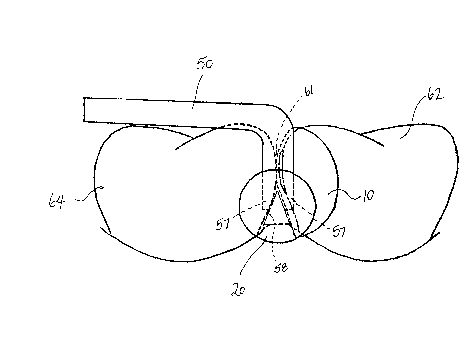
While the matrix 10, wedge 20 and clamp 50 can be used independently of each
other with other prior art devices, in a preferred embodiment the matrix, wedge and
the clamp of the present invention are used together to effect placement of a dental
filling which is cost effective and which provides firm contact in the contact area 61
between the placed filling material and the prepared tooth and, thereby, a well
15 sealed margin 38. Figures 4A and 4B, schematically illustrate a restoration
procedure which is being performed on a tooth 62. Tooth 62 is adjacent a second
tooth 64. Tooth 62 has had a portion of its crown removed to form a cavity 66 for
accepting an amount of dental filling material 67 such as light curable composite
resin.
Between teeth 62, 64 is inserted matrix 10 which acts as a mold around cavity 66against which the filling material can be placed. Side 12b of matrix is positioned
adjacent tooth 62. Wedge 20 is inserted between the teeth to extend into or through
the interproximal area. End 22 is exposed for directing theretowards concentrated
light. Wedge 20 forces matrix 10 in close contact with tooth 62 and is useful toconduct light interproximally.
To secure the upper portion of matrix 10 against tooth 62, clamp 50 is engaged
CA 022233~9 1997-12-02
- 14-
about tooth 62 and matrix 10. To engage clamp 50 over the tooth and the matrix, a
device is used to force the arms 52 of the clamp apart so that extensions 57 of tines
56 can be forced down on either side of the tooth. Tine 56, when placed, contacts
both tooth 62 and 64 and shields the interproximal area therebetween. Notches 585 fit over upper portion of wedge 20.
Matrix 10 is thereby securely held against tooth 62 and composite resin 67 can be
introduced to cavity 66. To cure the resinous material, concentrated light is directed
at end 22 of wedge 10. The light is conducted through the wedge and is refractedand reflected laterally outwardly therefrom by the striations on the wedge. Light is
10 prevented from curing the upper portion of the preparation by the positioning of the
extensions 57 of clamp 50 and by the positioning of the striated region on the
wedge.
It will be apparent that many other changes may be made to the illustrative
15 embodiments, while falling within the scope of the invention and it is intended that all
such changes be covered by the claims appended hereto.