Note : Les descriptions sont présentées dans la langue officielle dans laquelle elles ont été soumises.
CA 02227348 1998-O1-19
METHODS AND DEVICES FOR COLLECTION OF SOFT TISSUE
Field of the Invention
The present invention relates to methods and devices for tissue sampling, and
more specifically to improved instruments and methods for acquiring soft body
tissue.
Background of the Invention
It is often desirable and frequently necessary to sample or test a portion of
tissue from
humans and other animals, particularly in the diagnosis and treatment of
patients with
cancerous tumors, pre-malignant conditions, and other diseases or disorders.
Typically, in the case of breast cancer, there is a great emphasis on early
detection and diagnosis through the use of screening modalities, such as
physical
exarnination, and particularly mammography, which is capable of detecting very
small
abnormalities, often nonpalpable. When the physician establishes by means of a
mammogram or other screening modality that suspicious circumstances exist, a
biopsy
must be performed to capture tissue for a definitive diagnosis as to whether
the
suspicious lesion is cancerous. Biopsy may be done by an open or percutaneous
technique. Open biopsy, which is an invasive surgical procedure using a
scalpel and
involving direct vision of the target area, removes the entire mass
(excisional biopsy) or
a part of the mass (incisional biopsy). Percutaneous biopsy, on the other
hand, is
usually done with a needle-like instrument through a relatively small
incision, blindly or
with the aid of an artificial imaging device, and may be either a fine needle
aspiration
(FN,A) or a core biopsy. In FNA biopsy, individual cells or clusters of cells
are
obtained for cytologic examination and may be prepared such as in a
Papanicolaou
CA 02227348 2003-06-02
smear. In core biopsy, as the term suggests, a core or fragment of tissue is
obtained for
histologie examination which muy he dune via a frozen section or paraffin
section.
The type ofbiopsy utilised depends in large part on circumstances present with
respect to the patient, including the: location of" the Iesion~s) within the
body, and no single
procedure is ideal for all cases. 1-lowevcr, core biopsy is extremely usefttl
in a number of
conditions and is being used more frequently by the medical professican.
A very successful type of image guided percutaneous core breast biopsy
instrument currently available is a vacuum-assisted automatic core biopsy
device. One such
successful biopsy device, is shown and disclosed in LI.S. Patent No.
5,526,822, U.S. Patent
No. 5,649,547 and U.S. Patent ~Jo. 5,769,086, all of which art commonly owned
by the
assignee of the present application. 'this device, known commercially as the
MAMMOTOME~R~ Biopsy System, has the capability to actively capture tissue
prior to
cutting the tissue. Active captuti; allows fbr sampling through non-
homogeneous tissues,
meaning that the device is equally capable of cutting through hard and soft
tissue. The
device is comprised of a disposable probe, a motorized drive unit, and an
integrated vacuum
source. The probe is made of stainless steel and molded plastic and is
desiC,med for
collection of multiple tissue samples with a single insertion of the probe
into the tissue. The
tip of the probe is configured wstl~ a laterally diaposed sampling notch for
capturing tissue
samples. Orientation of the sang plc;: notch is directed by the physician, who
uses a
thumbwheel to direct tissue sat~npliog in any direction about the
circumference of the probe.
A hollow cylindrical cutter sevi°,rs and transports tissue samples to a
tissue collection
chamber for later testing.
While the MAMMO'l OME Biopsy System functions very well as a core biopsy
device, there are occasions wh~.;n, because of the size of a lasion, or its
location, it may be
advantageous to use a core biopsy device of a type disclosed in U.S_ Patent
No. 5,111,828 to
Kornberg et al., wherein the tissue receiving port is disposed at the distal
end of the device
and is oriented axially rather than laterally. A disadvantage of this type of
device, however,
is the lack of ability to effectively draw tissue into the receiving chamber
prior to and during
the tissue cutting process. A second ~:~isadvantage is the requirement to
withdraw
CA 02227348 1998-O1-19
the device from parent tissue and remove the first specimen, reassemble the
device, then
reintroduce the device for each desired specimen. A third disadvantage is the
necessity
of manually handling each specimen obtained.
On other occasions, the ability to sample any selected area of a cavity wall
from
within the cavity may be important, which ability requires the use of a
flexible probe.
Furthermore, it is desirable during the biopsy process to "stage" the spread
of a
cancer. For example, breast cancer starts in the milk ducts, the mammary
glands. The
initial change towards breast cancer is now thought to be the development of
atypical
ductal hyperplasia. The next step is thought to be represented by ductal
carcinoma in
situ. Finally, the last step in the development of breast cancer is
infiltrating ductal
carcinoma. By the time the breast cancer has reached the stage of infiltrative
ductal
carcinoma, breast cancer cells have developed the ability to migrate from the
duct of
origin, disassociate themselves from one another, and enter vascular
structures, such as
the llymphatic channels. When these malignant infiltrative ductal carcinoma
cells enter
the vascular system, they can spread or metastasize to other parts of the
body. It is this
metastatic process that ultimately leads to death from breast cancer.
When breast cancer cells enter the lymphatic system, they metastasize in an
orderly fashion to regional lymph nodes. Drainage can occur to the axillary
lymph
nodes, the supraclavicular lymph nodes, the lateral thoracic lymph nodes, and
to the
internal mammary lymph nodes.
It is the current standard of practice to determine if breast cancer cells
have
extended to regional lymph nodes by surgically performing an axillary lymph
node
dissection known as lymphadenectomy. In this open surgical procedure, a
relatively
large incision (5-10 cm), is made at the axilla (the armpit). Through this
incision, a
relatively large volume ( 15 to 30 grams) of fatty tissue and lymph node
tissue are
removed.
During this process, anywhere from 10 to 30 lymph nodes can be recovered and
submitted to pathology, where each of these lymph nodes is examined for the
presence
or absence of metastatic breast cancer. Based on positive lymph node findings,
systemic therapy will be given to the patient with breast cancer, including
chemotherapy. If, on the other hand, the lymph nodes of the axilla are free of
metastatic
disease, then the use of systemic therapies is limited.
3
CA 02227348 1998-O1-19
Surgical lymphadenectomy carries a low mortality, but high morbidity. The
most common morbidity is the development of lymph edema in the arm, which is
ipsilateral to the axilla dissected. The development of lymph edema in the
ipsilateral
arm is, at times, a debilitating complication. Another frequent complication
of surgical
lymphadenectomy is injury to sensory nerves in the region of the incision,
resulting in
permanent loss of sensation to the patient, and often in a disfiguring
condition termed
"winged scapula".
It has been shown in the examination of lymphatic drainage of melanoma, and
now shown in the lymphatic drainage of breast cancers, that lymphatic drainage
patterns
can be defined by the injection of a radioisotope (or other traceable marker
such as blue
dye;l immediately adjacent to the tumor. The isotope (or dye) is then
followed, either
visually, with a gamma camera imaging system, or with a Geiger counter-type of
counting system.
The spread of cancer cells is orderly, the first lymph node reached by the
drainage channels from the infected breast containing the most cancer cells.
Consequently, the first lymph node in the draining system is referred to as
the "sentinel"
lymph node.
It has been further shown, if one simply removes the sentinel lymph node, the
determination of whether or not breast cancer has metastasized to the regional
lymph
nodes of the axilla can be established without excision of the remaining lymph
nodes in
the ~~xilla. The surgical removal of only one lymph node greatly reduces the
complications of lymph node surgery including the morbidity of lymph edema.
It would be desirable to further reduce the morbidity of the axillary sentinel
lymph node biopsy if instrumentation were available to allow the sentinel
lymph node
to be identified and removed percutaneously with as little effect as possible
to the
surrounding tissue structure. The apparatus described in this patent can be
introduced
percutaneously through a small skin opening and directed to the sentinel lymph
node
thus eliminating open surgical exploration. Consequently, sentinel lymph node
biopsy
could be accomplished as an office procedure, eliminating hospitalization and
minimizing the recovery period.
The elements of a percutaneous sentinel lymph node biopsy are as follows: The
tumor site in the breast is injected with a radioisotope (such as technicium
99m labeled
4
CA 02227348 1998-O1-19
sulfur colloid) which travels via the lymphatic channels to the sentinel lymph
node.
The sentinel lymph node then becomes radioactively visible, or "hot." The
apparatus
hereafter described is able to identify or locate the radioactive lymph node
through
auditory and other signals, indicating when the apparatus is adjacent to the
sentinel
lymph node. The apparatus is further able to then characterize or "visualize"
the
surrounding tissue with the associated ultrasound portion of the apparatus. It
is
important to identify the associated structures adjacent to the lymph node,
because
relatively large blood vessels (arteries, veins,) and nerves traverse the
axilla. With the
combination of both Geiger counter and ultrasound identification, the sentinel
lymph
node can be identified and biopsied without entering a major blood vessel or
severing a
major nerve.
With a small entry site, no suturing is required (the procedure is
percutaneous),
and the patient may be sent home with a simple band-aid over the axillary
entry site.
The following day, the patient receives the results of the percutaneous
sentinel lymph
node biopsy determining whether or not metastatic disease is present or absent
in the
sentinel lymph node draining the affected breast.
Instruments are known in the prior art which could be adapted to perform some
of the procedures outlined above. For example, U.S. Patent No. 5,111,828 to
Kornberg
et al. discloses a percutaneous excisional breast biopsy device having a
cannula, open
distal and proximal ends, and a sharp cutting surface on the distal end. A
stylet extends
through the cannula and includes a distal puncturing end. A localization guide
wire is
used to direct the instrument to a biopsy site. The cannula is moved distally
to cut a
desired tissue specimen, after which a descending element is pushed to the
distal end of
the tissue specimen, then pulled proximally to sever the specimen completely
from
surrounding tissue.
A significant disadvantage of the Kornberg approach is that only one tissue
sample may be obtained for each insertion of the instrument into the patient's
body to
the biopsy site. Once the descending element has been pulled to sever the
tissue
sample, there is no opportunity to repeat the procedure while the instrument
remains in
place.
The present invention lacks the disadvantages and shortcomings of the prior
art
and provides an improved method and device for percutaneous excisional tissue
biopsy.
5
CA 02227348 1998-O1-19
The present invention may be used for purposes others than percutaneous
biopsy. For
example, the device may be used for general organ and tissue removal through a
trocar
to perform various laparascopic procedures including splenectomy, nephrectomy,
appendectomy and liver removal. The device may also be used laparascopically
through a trocar to remove abnormal growths such as polyps.
SummarJr of the Invention
This invention provides an inventive tissue sampling probe which offers many
advantages over probes available in the prior art. Unexpectedly superior
results are
obtained in connection with the retrieval of intact tissue specimens, because
of a unique
combination of cutting features, including, in particular, the employment of
an
electrosurgical cutting element which is extendible to permit ready severance
of the
distal end of the tissue specimen, without impact to surrounding tissue.
Additionally,
the inventive instrument may be advantageously designed so that portions of
the
inst~~ument which contact the patient's tissue or discharge (i.e. blood)
during a procedure
are modular and disposable, to permit ready replacement of those portions with
a new
modlule for an ensuing procedure, without the necessity of cleaning and
sterilizing the
instrument. The versatility ofthe invention permits its use in many
applications,
inch.~ding, for example, breast biopsies, intraoperative staging, laparoscopic
surgery,
and lymphadenectomy procedures.
More particularly, in one aspect of the invention, a tissue sampling apparatus
is
provided which comprises a tubular body having a primary lumen for receiving a
tissue
sample, wherein the tubular body has a distal end and a proximal end. An
electrosurgical cutting element, preferably a wire, is disposed along an axial
length of
the tubular body. The cutting element includes a distal cutting end and is
axially
slidable between an axially extended position and an axially retracted
position relative
to the tubular body. The instrument is particularly suited to axial cutting
when the wire
is retracted, as it is advanced distally through a tissue region from which a
tissue sample
is desired. When the wire is extended, it curves in a radial direction across
a portion of
the transverse dimension of the distal end of the tissue specimen, so that, as
the tubular
body is slowly rotated, the curved distal end of the cutting wire functions to
cleanly
6
CA 02227348 1998-O1-19
sever the distal end of the specimen from the remaining tissue without
impacting the
remaining tissue.
In another aspect of the invention, a tissue sampling apparatus is provided
whi~;.h comprises a tubular body having a primary lumen for receiving a tissue
sample,
haviing a distal end and a proximal end, wherein the tubular body is comprised
of
disposable materials. The apparatus further comprises an electrosurgical
cutting
element which is disposed along an axial length of the tubular body, and a
housing for
enclosing a portion of the tubular body, wherein the housing comprises a lid
portion
which is openable relative to a body portion of the housing. Advantageously,
the
tubular body is constructed in a modular fashion, so that it may be removed
from the
housing by opening the lid portion, and readily replaced by another tubular
body
module between medical procedures.
In still another aspect of the invention, a method of capturing a body tissue
sample is disclosed, wherein a tissue sampling apparatus comprising a tubular
body
having a lumen extending therethrough and a distal end is utilized. An
electrosurgical
cuttiing element having a distal end portion which is disposed distally of the
distal end
of the tubular body, and an actuator for moving (advancing and retracting) the
cutting
element, are also disposed on the tissue sampling apparatus. The method
comprises the
steps of energizing the electrosurgical cutting element using an
electrocautery
generator, and rotating the tubular body at a relatively high rate of speed.
Then the
tubular body is advanced through a tissue portion a desired distance so that
the
energized electrosurgical element cuts a generally cylindrical tissue sample
as the tissue
sample enters the lumen. In essence, the distal end of the tubular body
receives
(captures) the cylinder of tissue created as the tube and electrosurgical
element are
energized, rotated, and axially advanced simultaneously. Once the desired
tissue
sample length has been achieved, distal advancement of the instrument is
halted, and
the e;lectrosurgical cutting element is advanced linearly so that the distal
end portion
thereof extends radially inwardly across a portion of a distal end of the
tissue sample
core. Preferably simultaneously, the tubular body is rotated at a relatively
low rate of
speed, so that the distal end portion of the electrosurgical cutting element
severs the
tissue sample core from the tissue portion.
The invention, together with additional features and advantages thereof, may
7
CA 02227348 1998-O1-19
best be understood by reference to the following description taken in
conjunction with
the accompanying illustrative drawing.
Brief Description of the Drawing
Fig. 1 is a perspective view of a first preferred embodiment of the inventive
tissue sampling instrument;
Fig. 2 is a side view, in elevation, illustrating a tissue specimen entering
the
distal end of the inventive instrument shown in Fig. 1;
Figs. 3-8 are schematic side views of the distal end of the inventive
instrument
shown in Fig. 1, illustrating sequentially the relative position of the
electrocautery cutter
during a representative tissue specimen capturing procedure;
Fig. 9 is an enlarged view, in cross-section, of a portion of the distal end
of the
inventive instrument designated by the letter A in Fig. l;
Fig. 10 is a side view, in cross-section, of the inventive instrument
illustrated in
Fig. l;
Fig. 11 is a side view, in cross-section, of a second preferred embodiment of
the
inventive tissue sampling instrument;
Fig. 12 is a perspective view of the inventive embodiment illustrated in Fig.
11;
Figs. 13a and 13b are cross-sectional views illustrating, in isolation, the
tube
portion of the tissue sampling instrument embodiment shown in Fig. 12;
Fig. 14 is a perspective view of the embodiment illustrated in Fig. 11,
showing
operation of the tissue sampling embodiment as it approaches a tissue region
to be
sampled;
8
CA 02227348 1998-O1-19
Fig. 15 is a perspective view of a stand-alone sensing probe which may be used
in connection with either of the embodiments of Figs. 1 or 11; and
Figs. 16, 16a, and 16b are perspective views of a multi-vision probe which may
be used in connection with the embodiments of Figs. 1 or 11.
Description of the Invention
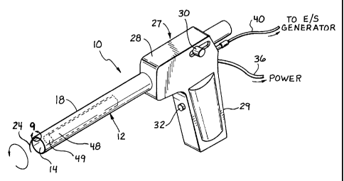
Referring now more particularly to Figs. 1 and 9, a first embodiment of the
invention is shown. The inventive tissue sampling probe 10 comprises a tube 12
having
a lumen 14. A cutter channel 16 extends axially along the length of the tube
outer wall
18 (Fig. 9). Extending axially through the cutter channel 16 is an
electrocautery cutter
wire: 20, preferably comprised of an electrically conductive shaped metallic
memory
wire;, such as Nitinol, which comprises a proximal portion 22 and a distal
portion 24.
The cutter wire 20 is preferably formed as a flattened round wire, because the
resultant
rect~~ngular shape, which makes the wire stiff in the x-direction and flexible
in the y-
direction, is preferred for resisting lateral forces which are encountered as
the wire is
rotated in tissue.
The tube 12 preferably comprises an inner layer 25 and an outer layer 26 (Fig.
9), the inner layer 25 being preferably fabricated of a non-conductive
radiolucent or
radiodense biocompatible composite material, such as a glass filament wound
epoxy
impregnated matrix material. Another possibility is to utilize a high density
polyethylene (HDPE), which is cross-linked with a high radiation dose, so that
it
behaves like a thermoset rather than a thermoplastic. The tube 12 preferably
has a
round cross-section, though other tube shapes may be used as well .
Advantageous
characteristics of the preferred composite material include light weight, high
melt
temperature, high dielectric, ductility, non-conductivity, and machinability.
An outer
layer 26 may be employed, the outer layer preferably comprising a high
dielectric
coating which is shrink wrapped about the outer diameter of the inner layer
25.
Bec,~use the preferred material for the inner layer 25 is easily machinable,
the channel
16 is preferably machined into the outer surface of inner layer 25.
Disposed proximally of the tube 12 is an actuator 27, which preferably
9
CA 02227348 1998-O1-19
corr~prises a housing 28, a fixed handle 29, a cutter advancement slide knob
30, and an
actuation switch 32. As illustrated in Fig. 10, the housing 28 encloses a
variable speed
electric motor 34 which is connected to a power supply via a power cord 36.
Operation
of the motor 34 drives interengaging gears 37 and 38, resulting in selective
rotation of
the tube 12.
An important aspect of the invention is the use of an electrocautery generator
(not shown). The electrical energy from the electrocautery (electrosurgical)
generator is
conducted along an electrical line 40 to the cutter wire 20, and is
selectively activated or
deacaivated using the electrosurgical energy actuation switch 32. As
illustrated in Fig.
10, the electrical line 40 is connected to an electrode advancement collar 41,
which
comprises an electrical
conl:act brush 42 and an electrode ring 44. A proximal end 46 of the cutter
wire
(electrode) 20 is attached to the electrode advancement collar. The cutter
advancement
slick: knob 30 is mechanically attached to the electrode advancement collar
41. Thus,
the electrode 20 is advanced distally when the cutter advancement slide knob
30 is
moved distally. For safety reasons, the slide knob 30 and the electrode
advancement
coll~~r 41 are electrically insulated from the cable 40, brush 42, and
electrode ring 44.
In operation, with respect to the embodiment of Figure 1, the electrocautery
genc;rator is activated using the actuation switch 32 to electrically activate
the cutter
wire 20. The switch 32 is preferably a momentary switch, which is actuated
only when
depressed and held by an operator. Simultaneously, the switch 32 actuates the
motor 34
to cause the tube 12 to rotate at a relatively high rate of speed by means of
gears 37, 38.
Then, the tube 12 is advanced by the operator through tissue with the cutter
wire 20 in
its retracted position, as shown in Fig. 3, to obtain the desired tissue
sample. With the
wire: 20 energized to function as an electrocautery cutter, the advancement of
the
rota~:ing tube 12 easily slices through the tissue to create a tissue specimen
48 (Fig. 1)
for capture within the lumen 14. In the preferred embodiment, depth marks (not
shown)
may be disposed axially along the exterior surface of the tube 12 in order to
assist the
physician in determining when the tube 12 has been advanced to the desired
position.
In its preferred operational mode, the energized conductive cutter wire 20
CA 02227348 2003-06-02
functions to define .and cut a tissue sample 48 having approximately the same
internal
diameter or cross-sectional shape; as that of the tube l2. 'fhe distal end of
the tube 12
receives the generally cylindrical tissue sample, which is created as the
tutee and cutter wire
are energized, rotated, arid axially advanced simultaneously. Once a sample of
adequate
length has been secured, advancement of the tube 12 is halted, and the cutter
wire 20 is
advanced distally relative to the tube 12 by sliding floe cutter advancement
slide knob 30
distally. Distal advancement of the cutter wire 2() is illustrated
sequentially in Figs. 4, 5, and
6. As shown in Fig. ~, the cutter wire 20 is fully advanced so that the
electrically energized
distal end 24 is curved radially i3nwardly to sever a portion of the distal
end 49 of the tissue
specimen 48 (Fig. '?). While the wire 20 is in its fully advanced position,
the tube 12 is
rotated at a relatively slaw rate c>f speed, by operation of the motor 34,
until the tube 12 has
been rotated at least 180 degreea, to the position illustrated in 1~ig. 7, and
preferably 360
degrees, to the position iflustratc:d in Fig. 8. In order to rotate the tube
12 at the second
lower rate of speed., either the svu itch 32 may be actuated to a second
operating position, or a
second switch may be utilized. This slow rotation of the tube 12 permits the
energized
distal end 24 of the; cutter wire f.0 tc:~ sewer the entire distal end 49 of
the tissue specimen 48,
thereby capturing the entire spe~:.innen 48 within t:he lumen 14 of the
instmment 10, as
shown in Figs. 1 and 2.
Once the tissue specimen has been captured within the lumen 14, one or more
additional samples. may be obtained and accommodated within the lumen if'
desired. When
the desired tissue samples have: been obtained. the instrument may be removed
from the
patient's body so that the tissue samples) may be extracted and examined. In
order to
expedite tissue sample capture, the interior surface of the tube 12 may be
coated to reduce
frictional contact between the tccbe and the tissue sample as it travels
through the lumen 14.
Though in the preferr-c~d embodiment, it is not necessary to utilize a source
of
suction (vacuum) in order to aet.ively draw the tissue sample into the tubular
body 12, it is
feasible, and in some instances desirable, to do so, in a manner similar to
that disclosed in
parent U.S. Patent No. 5,810,8()<. In such an instance, a source of
CA 02227348 1998-O1-19
vacuum pressure would be employed for drawing a vacuum through the primary
lumen
14, so that the vacuum pressure in the primary lumen draws tissue to be
sampled into
the primary lumen as the electrosurgical cutting element 20 cuts the drawn
tissue. The
vacuum pressure may then act to assist transport of the tissue specimen
proximally
through the primary lumen to a tissue receptacle.
Many other embodiments may be employed other than the embodiment
illustrated in Fig. 1. For example, a modified embodiment, which is presently
preferred,
is il lustrated in Figs. 11 and 12, wherein all elements corresponding to
those of the
embodiment of Figure 1 are designated by like reference numerals, succeeded by
the
letter "a". In this embodiment, a modified actuation system is employed. The
modified actuation system includes a first actuation switch 32a, disposed on a
proximal
surface of the handle 29a, which is preferably a momentary switch (actuated
only when
physically depressed and held by the operator). The first actuation switch 32a
simultaneously actuates the motor 34a to rotate the tube 12a at a relatively
high
rotational velocity, and energizes the cutter wire 20a for electrosurgical
cutting.
Additionally, a cutter wire advancement trigger 50 is provided distally of the
handle
29a. The cutter wire advancement trigger 50 is pivotally mounted, via pivot
pin 52, to a
fork 54, as illustrated in Figs. 11 and 12, and is attached at its upper end
to an electrode
advancement plate 56 (Fig. 11 ). Such attachment between the trigger 50 and
the
advancement plate 56 may be by means of any conventionally known mechanical
fastc;ning system. In turn, the electrode advancement plate is slidably
disposed on a
carriage pin 58, and is disposed between an electrode carriage block 60 and a
proximal
surface 62 of the housing 28a, the carriage block 60 also being slidably
disposed on the
carriage pin 58. An upper portion 64 of the carriage block 60 is fixedly
attached to the
electrode advancement collar 41a. A second actuation switch 66 is disposed on
the
trig~;er 50. The switch 66 is adapted to simultaneously energize the cutter
wire 20a and
to acauate the motor 34a to rotate the tube 12a, as is the first switch 32a,
except that
when the second switch is actuated, the motor operates at a lower speed to
rotate the
tube 12a at a relatively low rotational velocity. A biasing spring 68 is
disposed on the
carriiage pin 58, between the carriage block 60 and a distal portion 70 of the
housing
12
CA 02227348 1998-O1-19
28a., to bias the carriage block 60 proximally, so that the cutter wire
(electrode) 20a is
biased to its retracted position.
An advantageous feature of the inventive embodiment of Figs. 11 and 12 is that
it is adapted to have a modular construction, so that portions of the
instrument having
physical contact with a patient's tissue and/or blood during a medical
procedure may be
disposed of and readily replaced by a practitioner. This modularity permits
expedited
reuse of the instrument for another patient procedure without the necessity
for extensive
cleaning and sterilization. In particular, the housing 28a is constructed to
comprise a lid
72 which is attached by means of hinges 74 to the main housing portion 76 so
that the
housing 28a is openable to permit access to the entire tube portion 12a. When
closed,
the lid 72 is secured by a latch 78. Thus, the entire tube portion 12a, as
illustrated in
Figs.. 13a and 13b, may be readily installed in or removed from the housing
28a of the
instrument l0a by a practitioner or an assistant between procedures. The
entire tube
portion 12a, including the electrode advancement collar 41a and the gear 38a,
is
preferably constructed of disposable materials, such as biocompatible plastics
or
composite materials, so that it may be made disposable after a single use for
a
reasonable cost.
In operation, with reference to Figs. 11-13b, a practitioner desiring to
obtain a
particular tissue sample from a patient may grasp the handle 29a of the
instrument l0a
and move the instrument l0a toward the targeted entry point on the patient's
body using
known imaging techniques. As the distal end of the tube 12a approaches entry
into the
body of the patient, switch 32a is actuated by the practitioner depressing and
holding
same so that the cutter wire 20a is energized and the motor 34a is
simultaneously
actuated to rotate the tube relatively quickly, in order to enhance the
cutting process.
During the ensuing period of time, the instrument continues to be advanced
through the
patient's tissue, with the cutter wire 20a biased by spring 68 to its
retracted position, as
illustrated in Fig. 13a, until a tissue specimen 48a of a desired length is
captured within
the lumen 14a of the tube 12a. With the wire 20a energized and retracted, and
the tube
12a rotating at a relatively high rotational velocity, the entire distal end
of the tube 12a
functions effectively as a cutting element to readily obtain a tissue sample
core from the
13
CA 02227348 1998-O1-19
desired tissue area. Again, as in the first embodiment, depth marks (not
shown) may be
disposed axially along the exterior surface of the tube 12a to assist the
physician in
determining when the tube 12a has been advanced to the desired position.
In its preferred operational mode, the energized conductive cutter wire 20a
functions to cut a tissue sample 44a having approximately the same diameter or
cross-
sectional shape as that of the inside diameter of tube 12a. Once a sample of
adequate
length has been secured, advancement of the instrument 1 Oa is halted, and the
cutter
wire; 20a is advanced by depressing the cutter wire advancement trigger 50 so
that it
pivots proximally about the pivot pin 52, from the position shown in Fig. 11
to the
position shown in Fig. 12. This pivoting motion causes the electrode
advancement plate
56 t~o move distally, thereby contacting the carriage block 60 and pushing it
distally as
well, against the bias of the spring 68. This movement of the carriage block
60 in turn
causes the electrode advancement collar 41a to slide distally, thereby
extending the
electrode (cutter wire) 20a to its extended position, as shown in Figs. 12 and
13b.
Contact of the electrode advancement plate 56 with the fork 54 serves as a
stop, to
ensure that the cutter wire 20a is only advanced a desired distance to create
the curved
portion 24a for severing the distal end of the specimen 48a.
Advantageously, as the practitioner's fingers grip the trigger 50 and depress
it
proa:imally to advance the cutter wire 20a, the switch 66 is simultaneously
depressed,
thereby actuating the motor 34a to rotate the tube 12a at a relatively slow
rotational
velocity, as opposed to the relatively high rotational velocity initiated by
actuation of
the switch 32a. Depression of the switch 66, which is preferably a momentary
switch
(like; switch 32a), also simultaneously energizes the cutter wire 20a to
initiate an
electrosurgical cutting capability. Applicants have found that the ability to
simultaneously advance the cutting wire 20a distally and to slowly rotate the
tube 12a is
benc;ficial to the tissue capture process, relative to the alternative of
first extending the
wire to its advanced position, and then initiating rotation of the tube 12a,
which was
originally thought to be necessary in order to prevent excessive lateral
stresses (torque)
on the cutting wire as it is being extended, due to the rotation of the tube
12a.
Once the cutter wire 20a is energized and fully advanced to its extended
14
CA 02227348 1998-O1-19
posiition, with the tube 12a rotating relatively slowly, due to actuation of
the switch 66,
as illustrated in Digs. 12 and 13b, the energized distal end 24a of the wire
20a functions
to sever the entire distal end 49 of the tissue specimen 48a, as in the first
embodiment
illustrated in Fig. 1. Once severed, the tissue specimen is completely
captured within
the ;lumen 14a of the instrument 1 Oa (Fig. 12), and the instrument may be
withdrawn
from the patient's body to retrieve the specimen for examination.
Alternatively, a
source of vacuum could be employed to assist in drawing tissue into the tube
12a and/or
to assist in transporting the tissue specimen proximally through the tube 12a
into a
tissue receptacle (not shown).
In order to expedite preparation of the instrument for another procedure on a
different patient, once the specimen 48a has been retrieved, the lid 72 of the
housing
28a may be opened, and tl~e used module 12a separated from the instrument and
discarded as medical waste. 'then, a new module 12a may be installed within
the
housing, and the lid secured in a closed position. Of course, the instrument
may be used
multiple times on the same patient without sterilization or replacement of the
disposable
module.
A particularly advantageous aspect of the invention is its ability to be used
in
connection with sensing probes for identifying and locating desired tissue to
be
sampled. For example, ultrasound probes or radiation detecting (Geiger) probes
may be
employed, such as those disclosed in U.S. Patent Nos. 4,959,547, 5,036,201,
5,1 19,818,
5,148,040, 5,170,055, and 5,246,005, which are assigned to Care Wise Medical
Products Corporation of Morgan 1-fill, California. Referring particularly
now to Figs. 15-16b, the instrument l0a illustrated
in Fig. 1 1 is shown, though the instrument 10 illustrated in Fig. 1 or other
similar
instruments could be substituted therefor. As illustrated in Figs. 11, 12,
13a, and 13b,
. the proximal end 78 of the tube 12a is open, so that there is a sight line
through the
entire lumen 14a of the tube 12a, from the proximal end 78 to the distal end
of the tube
12a. The proximal end 78 may be configured to receive a sensing probe 80 or 82
(Figs.
15 and 16).
A stand alone sensing probe 80 is illustrated in Fig. I5, which may comprise
CA 02227348 1998-O1-19
either an ultrasonic probe or a geiger probe, both of which are conventionally
known in
the medical diagnostic arts. The probe 80 is specifically configured to mate
into the
through hole 78 of the soft tissue acquisition device 10a. Electronic control
lines 84
extend from a proximal end of the probe 80 to appropriate control units, for
receiving
and processing information obtained by the probe.
Alternatively, a multi-vision probe, such as the probe 82 illustrated in Fig.
16,
may be utilized. This type of probe is capable of functioning both as an
ultrasonic
prone and as a geiger probe, and has two sets of control lines 86 and 88 for
communicating with ultrasonic and geiger electronic control units,
respectively.
In operation, a lesion (tissue) 90 to be sampled (Fig. 15) is located using a
mufti-vision probe 82 or a combination of stand-alone probes 80, which are
disposed in
the soft tissue acquisition device 1 Oa. The geiger portion of the probe
provides an X-Y
location on the surface of the tissue to be sampled, while the ultrasonic
portion provides
depth information as well as X-Y location information. Then, the soft tissue
acquisition
device l0a is held in position, while the sensing probes) is (are) removed.
Following
removal of the sensing probe, a tissue sample may be obtained using the
methods
described supra.
While this invention has been described with respect to various specific
examples and embodiments, it is to be understood that the invention is not
limited
thereto and that it can be variously practiced within the scope of the
following claims.
16