Note : Les descriptions sont présentées dans la langue officielle dans laquelle elles ont été soumises.
CA 02227937 1998-O1-26
SEI 97-39
TITLE OF THE INVENTION
WAVELENGTH-VARIABLE LIGHT SOURCE AND OTDR APPARATUS
Back~~round of the Invention
Field of the Invention
The present invention relates to a light source discretely
oscillating a desired wavelength and, in particular, to a
wavelength-variable light source loaded in an apparatusfor
measuring a loss distribution of a branch optical line whose
one end is divided into a plurality of light-branching lines,
and an OTDR apparatus.
Related Background Art
A conventional OTDR apparatus is disclosed in
Japanese Patent Application Laid-Open No. 2-141641, which
indicates that a wavelength-variable light source is
efficient for inspecting a defect or a physical quantity
such as temperature within a system to be measured having
a branch device.
Summary of the Invention
Conventional wavelength-variable lightsources added
to an OTDR apparatus include the one using a method in which
a reflecting plate of diffraction gratings is disposed
outside a light-emitting device, with its angle being
adjusted so as to change wavelength of oscillation; a fiber
type laser using a wavelength-variable filter; and the like.
These light sources necessitate a large number of
constituent parts, each of which is expensive, a high level
1
CA 02227937 1998-O1-26
SEI 97-39
of assembling technique, and the like.
Therefore, it is an object of the present invention
to provides a wavelength-variable light source and an OTDR
apparatus, which are inexpensive and have a simple
configuration. _
A wavelength-variable light source in accordance with
the present invention comprises: a semiconductor light-
emitting device; a first light waveguide optically coupled
to said semiconductor light-emitting device; a plurality
of second :Light waveguides each of which having diffraction
grating with different reflection wavelengths formed
therein; and a first optical switch which selectively
optically couples an output end of said first light
waveguide to one of input ends of said second light
waveguides.
A preferable first wavelength-variable light source
in accordance with the present invention is characterized
in that it comprises a semiconductor light-emitting device
which can emit light having a plurality of predetermined
wavelength; a first light waveguide optically coupled to
the semiconductor light-emitting device; a plurality of
second light waveguides in which light-waveguide-type
diffraction gratings having different reflection
wavelengths are formed; a first optical switch for
selectively optically coupling an output end of the first
light waveguide to an input end of a plurality of the second
2
CA 02227937 1998-O1-26
SEI 97-39
light waveguides; and a condenser for optically coupling
a plurality of output ends of a plurality of the second light
waveguides to an input end of a light waveguide in a next
stage.
In accordance with the wavelength-variable light
source of the present invention, a resonator is formed by
the semiconductor light-emitting device, light-
waveguide-type diffraction grating, and the like; so that,
of wavelengths oscillated by the semiconductor light-
emitting device, light having a wavelength reflected by the
light-waveguide-type diffraction grating is repeatedly
reflected within the resonator in a reciprocating fashion,
whereby pulse light grown to have a predetermined amplitude
is outputted from the diffraction grating of the second
light waveguide. Accordingly, a plurality of light-
waveguide-type diffraction gratings having different
reflection wavelength regions are disposed in parallel,
input light thereto is switched by the first optical switch,
so that output light beams with different wa-velengths are
successively sent out, and the output light is coupled to
the light waveguide of the next stage by means of the
condenser, whereby light having a desired wavelength can
be oscillated at a low cost.
The :fading noise noticeable upon measurement of a loss
distribution in an optical fiber tends to occur when the
wavelength band of the pulse light to be measured becomes
3
CA 02227937 1998-O1-26
SEI 97-39
1 nm or less. From the viewpoint of suppressing the fading
noise, it is preferred that the reflection wavelength band
of the light-waveguide-type diffraction grating be set to
at least 1 nm by chirped grating.
_ In the wavelength-variable light source of the
present invention, there may be a case where a predetermined
wavelength band of light cannot be oscillated by a single
semiconductor light-emitting device. In such a case, a
plurality of semiconductor light-emitting devices having
different wavelength regions may be disposed in parallel
so that they bear respective parts of the wavelength region.
It has experimentally been confirmed that, in the case
where the optical length between the semiconductor
light-emitting device and the diffraction grating is 700
mm or less, the resonator applied to the present invention
can oscillate a pulse having a peak value of 10 dB or higher
in a wavelength band of 5 nm when the wavelength intervals
are set to 5 nm, thereby allowing eight wavelength regions
- of pulse light to be sent out. A wavelength-variable light
source equipped with such a resonator can measure a loss
distribution in an optical line having eight branches, thus
being fully capable of practical use.
Alsa, it has experimentally been confirmed that, when
the optical length of the resonator is set to 300 mm or less,
the number of reciprocating reflections within the
resonator further increases, thus allowing a pulse having
4
CA 02227937 1998-O1-26
SEI 97-39
a peak value of 20 dB or higher in a wavelength band of 5
nm when the wavelength intervals are set to 5 nm to be
oscillated, whereby eight wavelength regions of pulse light
can be sent out. A wavelength-variable light source
equipped with such a resonator can be used as a light source
having an excellent crosstalk characteristic. While the
optical length of.the resonator is preferably as short as
possible, its practical lower limit is determined by the
minimum size required for forming the resonator.
A preferable second wavelength-variable light source
in accordance with the present invention is characterized
in that it comprises a semiconductor light-emitting device
for emitting light having a plurality of predetermined
wavelength; a first light waveguide optically coupled to
the semiconductor light-emitting device; a plurality of
second light waveguides in which light-waveguide-type
diffraction gratings having different reflection
wavelengths are formed; a first optical switch for
selectively optiEally coupling an output end of the first
light waveguide to an input end of a plurality of the second
light waveguides; and a second optical switch for
selectively optically coupling a plurality of output ends
of a plurality of the second light waveguides to an input
end of a light waveguide in a next stage.
In the wavelength-variable light source of this
invention, in place of the condenser, the second optical
5
CA 02227937 1998-O1-26
SEI 97-39
switch selectively optically couples a plurality of output
ends of a plurality of the second light waveguides to an
input end of a light waveguide in the next stage. Since the
second optical switch has basically the same configuration
as that of the first switch, it becomes inexpensive and easy
to handle.
In the wavelength-variable light source of the
present invention, when the first light waveguide and the
next-stage light waveguide are made stationary while the
second light waveguides are attached to a common movable
mechanism, the first and second switches can be
simultaneously switched upon a single switching operation,
whereby its handling becomes easier. On the other hand,
when the second light waveguides are made stationary while
the first light waveguide and the next-stage light waveguide
are attached to a common movable mechanism, the number of
light waveguides on the moving side can be reduced, whereby
the switching operation can be performed smoothly.
Preferably, in the wavelength-variable light source
of the present invention, on the output side of the
light-waveguide-type diffraction grating provided for each
of the second light waveguides, a band-pass filter which
transmits therethrough light in a wavelength region
narrower than the wavelength region reflected by the
light-waveguide-type diffraction grating is disposed;
since, even when fluctuation in oscillation wavelength or
6
CA 02227937 1998-O1-26
SEI 97-39
the like occurs, the band-pass filter would act to correct
the fluctuated wavelength to a predetermined wavelength
region.
Also, the wavelength-variable light source in
accordance with the present invention preferably comprises
physical quantity changing means which changes a physical
quantity of a light-waveguide-type diffraction grating such
as temperature or tension, so as to vary the reflection
wavelength of the light-waveguide-type diffraction
grating.
Further, the above-mentioned wavelength-variable
light source is preferably applied to an OTDR apparatus.
The OTDR apparatus in accordance with the present invention
is characterized in that it comprises the above-mentioned
wavelength-variable lightsource, and a photodetector which
feeds light outputted from the wavelength-variable light
source into a system to be measured and detects
backscattering light from the system to be measured. The
- light outputted from the light source is reflected at a
predetermined position within the system to be measured,
so as to return to the photodetector. The time required for
light to effect this round travel is proportional to the
distance to the predetermined position. Accordingly, as
the photodetector detects the backscattering light
intensity during the time of this round travel, information
about a physical quantity at the predetermined position of
7
CA 02227937 1998-O1-26
SEI 97-39
the system to be measured such as defect, temperature, or
the like, for example, can be observed.
Also, the OTDR apparatus in accordance with the
present invention preferably comprises control means which
controls, when an intensity of backscattering light from
a position ahead of a specific position of the system to
be measured detected by the photodetector becomes lower than
a predetermined level, the physical quantity changing means
so as to vary the reflection wavelength of the light-
waveguide-type diffraction grating. When a branch device,
for example, exists at a specific position, the
backscattering light intensity decreases at this position.
The backscattering light intensity from a position ahead
of this specific position is lower than that from the
position where the branch device exists. When the
transmission wavelength characteristic of the branch device
greatly deviates from its designed value depending on
temperature, light is not sufficiently transmitted
therethrough. Consequently, the backscattering light
intensity from the position ahead of this position
remarkably decreases, thereby becoming lower than a
predetermined level. In such a case, the control means
controls the physical quantity changing means so as to
slightly change the wavelength of light outputted from the
wavelength-variable light source such that this light is
efficiently transmitted through the branch device. Namely,
8
CA 02227937 1998-O1-26
SEI 97-39
it is preferred that the control means regulate the phys ical
quantity changing means such that the backscattering light
intensity from a predetermined position within the system
to be measured is maximized.
_ The present invention will be more fully understood
from the detailed description given hereinbelow and the
accompanying drawings, which are given by way of
illustration only and are not to be considered as limiting
the present invention.
Further scope of applicability of the present
invention will become apparent from the detailed
description given hereinafter. However, it should be
understood that the detailed description and specific
examples, while indicating preferred embodiments of the
invention, are given by way of illustration only, since
various changes and modifications within the spirit and
scope of the invention will be apparent to those skilled
in the art from this detailed description.
Hrief Desc_r;,p~ion of the Drawings
Fig. 1 is a view showing a configuration of a
wavelength-variable light source in accordance with the
present embodiment.
Fig. 2 is a view showing a configuration of a resonator
in the wavelength-variable light source of the present
embodiment.
Figs. 3A, 3B, 3C, 3D and 3E are views showing
9
CA 02227937 1998-O1-26
SEI 97-39
relationships between output wavelengths in the
wavelength-variable light source shown in Fig. 1.
Fig. 4 is a view showing a configuration of the
wavelength-variable light source in accordance with the
present embodiment.
Figs. 5A, 5B, 5C, 5D, 5E and 5F are views showing
relationships between output wavelengths in the
wavelength-variable light source shown in Fig. 4.
Fig. 6 is a view showing another configuration of the
wavelength-variable light source in accordance with the
present embodiment.
Fig. 7 is a view showing another configuration of the
wavelength-variable light source in accordance with the
present embodiment.
Fig. 8 is a view showing another configuration of the
wavelength-variable light source in accordance with the
present embodiment.
Figs . 9A, 9B, 9C, 9D, 9E, 9F, 9G, 9H and 9I are views
- showing relationships between output wavelengths in the
wavelength-variable light source shown in Fig. 8.
Figs. 10A, lOB and lOC are views showing output
waveforms of respective parts in the wavelength-variable
light source in accordance with Examples.
Fig. 11 is an explanatory view of a branch optical
line.
Fig. 12 is a view for explaining a system for measuring
CA 02227937 1998-O1-26
SEI 97-39
a loss distribution of an optical line.
Fig. 13 is a view showing a relationship between the
power measured by the measurement system of Fig. 12 and
distance.
Fig. 14 is an overall view of a wavelength-variable
light source and a system to which this light source is
applied.
Figs. 15A, 15B, 15C, 15D and 15E are views showing
relationships between output wavelengths of the
wavelength-variable light source shown in Fig. 14 and the
wavelengths transmitted to the branch optical line.
Fig. 16 is a perspective view of a wavelength-variable
light source.
Fig. 17 is a graph showing a dependency of
backscattering light intensity (I) on distance (L).
In the following, modes for carrying out the present
invention will be explained in detail with reference to the
accompanying drawings. In the explanation of the drawings, -
constituents identical to each other will be referred to
with numerals identical to each other, without their
overlapping descriptions being repeated.
Fig. 1 is a view showing a configuration of the first
wavelength-variable light source in accordance with an
embodiment, whereas Fig. 2 is a view showing, of the
wavelength-variable light source, a part forming a
11
CA 02227937 1998-O1-26
SEI 97-39
resonator. In Fig. 1, a wavelength-variable light source
1 comprises a semiconductor light-emitting device 11; a
first light waveguide 31 constituted by an optical fiber
connected to the semiconductor light-emitting device 11;
second light waveguides 32-1 to 32-4, disposed in parallel
to each other at respective positions where they can oppose
the first light waveguide 31, in which light-waveguide-
type diffraction gratings 21-1 to 21-4 having reflection
wavelengths different from each other are respectively
formed; a first optical switch 12 formed such that the first
light waveguide 31 can selectively connect with the second
light waveguides 32-1 to 32-4 while relatively moving in
directions of arrow 60 along input end faces thereof; and
a condenser 13 which couples and emits output light beams
having different wavelengths respectively sent out from the
second light waveguides 32-1 to 32-4 to an input end of a
light waveguide 33.
Further, as shown in Figs. 1 and 2, the semiconductor
light-emitting-device 11, first light waveguide 31, second
light waveguides 32-1 to 32-4, and light-waveguide-type
diffraction gratings 21-1 to 21-4 form a resonator 40, in
which light having a wavelength reflected by the light-
waveguide-type diffraction gratings 21-1 to 21-4 is
reflected to-and-fro between a reflecting plate 11-0
disposed on the rear side of the semiconductor light-
emitting device 11 and the light-waveguide-type diffraction
12
CA 02227937 1998-O1-26
SEI 97-39
gratings 21-1 to 21-4 (optical length: L). The condenser
13 is formed in combination with a multiplexer, a
photocoupler in which two optical fibers are distributed
and connected together, or the like, thereby yielding a good
wavelength-preserving characteristic. Though LDs are
normally formed with the reflecting plate 11-0, some LEDs
lack it. Preferably, the reflecting plate 11-0 has a
reflectivity of at least 90%, whereas the surface opposite
thereto has a reflectivity of 0.1% or lower.
In the wavelength-variable light source 1 shown in
Fig. 1, light oscillated by the semiconductor light-
emitting device 11 reaches the light-waveguide-type
diffraction grating 21-1 by way of the first light waveguide
31 and the second light waveguide 32-1, whereby a wavelength
~,1 determined by the interval of the light-waveguide-type
diffraction grating 21-1, whose core periodically changes
its refractive index in the core axis direction, is
reflected. Thus reflected light ~,1 is reflected again by
the reflecting plate 11-0, and advances toward the
light-waveguide-type diffraction grating 21-1 together
with the light oscillated by the semiconductor light-
emitting device 11. After reflections are subsequently
repeated in a s imilar manner, light having a wavelength of
hl is sent to the condenser 13. Since the second light
waveguides 32-1 to 32-4 respectively having a plurality of
light-waveguide-type diffraction gratings 21-1 to 21-4 with
13
CA 02227937 1998-O1-26
SEI 97-39
reflection wavelength regions different from each other are
disposed in parallel on the output side of the first optical
switch 12 ; as they are switched by the first optical switch
12, light beams respectively having wavelengths ~,1 to
different from each other can be successively oscillated
and sent out.
The greater is the number of reflections repeated
within the resonator 40, the more likely the wavelength band
confined within a pulse waveform would coincide with the
wavelength band characteristic of the diffraction grating
21. Figs. 3A is a view showing a gain waveform of the
semiconductor light-emitting device 11, and Figs. 3B to 3E
show optical outputs oscillated by the respective second
light waveguides 32-1 to 32-4.
The light source of this embodiment is configured such
that the light-waveguide-type diffraction gratings 21-1 to
21-4 are disposed in parallel, and while they are switched
by the optical switch or the like, a predetermined
- wavelength of light is oscillated, whereby a
wavelength-variable light source having a simple
configuration can be obtained inexpensively.
Also, the oscillation wavelength and its band are
determined by the reflection wavelength of the light-
waveguide-type diffraction grating and can be controlled
by the optical length between the semiconductor light-
emitting device and the light-waveguide-type diffraction
14
CA 02227937 1998-O1-26
SEI 97-39
grating, whereby the oscillation wavelength band can be
minutely adjusted. Here, the fading noise noticeable upon
measurement of a loss distribut~.on of an optical fiber tends
to occur when the wavelength band confined in the pulse light
to be measured is 1 nm or less. From the viewpoint of
suppressing the fading noise, it is preferred that the
reflection wavelength band of the light-waveguide-type
diffraction grating be set to 1 nm or more by chirp grating
which imparts a variation to the grating interval.
Next, there may occur a case where the number of
light-branching lines is so large that a single
semiconductor light-emitting device cannot oscillate the
whole measurement wavelength band. In such a case, as shown
in Fig. 4, a plurality of semiconductor light-emitting
devices 11-1 and 11-2 having light-emitting wavelength
bands different from each other are disposed in parallel
so as to bear different parts of the wavelength region. Figs .
5A and 5'B are graphs showing respective gain waveforms of
the t-wo semiconductor light-emitting devices 11-1 and 11-2
having light-emitting wavelength bands different from each
other, whereas Figs. 5C to 5F are graphs showing output
wavelengths respectively transmitted to the second light
waveguides 32-1 to 32-4 in sequence.
Fig. 6 is a view showing a configurational mode of
a second wavelength-variable light source in accordance
with this embodiment, in which the semiconductor light-
CA 02227937 1998-O1-26
SEI 97-39
emitting device 11 and first optical switch 12 are the same
as those in Fig. 1. The condenser means shown in Fig. 6 is
a second optical switch 14 in which a third light waveguide
34 is disposed at a position where it can oppose output ends
of the second light waveguides 32-1 to 32-4, and the input
end of the third light waveguide 34 can selectively connect
with the second light waveguides 32-1 to 32-4 while
relatively moving along the output end faces thereof in
directions of arrow 60. Since this condenser means has a
further less number of parts and its basic configuration
is identical to that of the first optical switch 12, it
becomes inexpensive and easy to handle.
In thus configured light source, when the first and
third light waveguides 31 and 34 are made stationary while
the second light waveguides 32 are attached to a common
movable mechanism 81, and the movable mechanism 81 is moved
in directions of arrow 60; the first and second optical
switches 12 and 14 can be switched simultaneously, and light
beams having wavelengths ~,1 to ~., different from each other
can be emitted from the third light waveguide 34. Not only
the output waveform of the semiconductor light-emitting
device 11 but also the output waveforms of the second light
waveguides 32-1 to 32-4 and third light waveguide 34 are
the same as those of Figs. 3A to 3E.
Fig. 7 is a view showing another configurational mode
of the second wavelength-variable light source in
16
CA 02227937 1998-O1-26
SEI 97-39
accordance with this embodiment, in which the semiconductor
light-emitting device 11 and first optical switch 12 are
the same as those of Fig. 1. The condenser means shown in
Fig. 7 is a second optical switch 14 in which the second
light waveguides 32-1 to 32-4 are bent like letter U so as
to align their output ends with their input ends, the third
light waveguide 34 is disposed at a position where it can
oppose the output ends of the second light waveguides 32-1
to 32-4, and the input end of the third light waveguide 34
can selectively connect with the second light waveguides
32-1 to 32-4 while relatively moving along the output end
faces thereof. As the condenser means 14 is formed as being
bent like U, this configuration is suitable for the case
where the line to be measured is oriented in the same
direction as its measuring apparatus . Not only the output
waveform of the semiconductor light-emitting device 11 but
also the output waveforms of the second light waveguides
32-1 to 32-4 and third light waveguide 34 are the same as
that of Fig. 2.
Though the first and second optical switches 12 and
14 shown in Figs. 6 and 7 relate to a case where they are
switched while the light waveguide to be connected is
mechanically moved, such switching can be effected at a high
speed when a configuration in which they are electrically
switched is employed.
Though the wavelength-variable light source 1 in this
17
CA 02227937 1998-O1-26
SEI 97-39
embodiment can emit pulse light having a predetermined
wavelength region by means of the light-waveguide-type
diffraction gratings 21-1 to 21-4 and resonator 40, it is
preferable that, as shown in Fig. 8, band-pass filters 50-1
to 50-4 respectively transmitting therethrough wavelength
regions of light corresponding to the reflection wavelength
regions of the discrete diffraction gratings be disposed
on the output side of the light-waveguide-type diffraction
gratings 21-1 to 21-4, since they act to correct fluctuation
which may occur in oscillation wavelength or oscillation
waveform. Figs. 9A shows oscillation waveform of the
semiconductor light-emitting device 11, Figs 9B to 9E show
output waveforms of the light-waveguide-type diffraction
gratings 21-1 to 21-4 when their oscillation wavelength or
oscillation waveform is fluctuated, and Figs. 9F to 9I show
their output waveforms after corrected by the band-pass
filters 50-1 to 50-4. Namely, it is preferred in the
wavelength-variable light source in accordance with this
embodiment that, on the output side of the light- _
waveguide-type diffraction gratings 21-1 to 21-4
respectively formed in the second light waveguides, the
band-pass filters 50-1 to 50-4 each transmitting
therethrough light having a wavelength region narrower than
the wavelength region reflected by its corresponding
light-waveguide-type diffraction grating be disposed,
since they act to correct, even when fluctuation of
18
CA 02227937 1998-O1-26
SEI 97-39
oscillation wavelength band or the like occurs, such
fluctuation to a predetermined wavelength region.
(Example 1)
Pulse light was oscillated by the wavelength-variable
light source 1 having the configuration shown in Fig. 1.
As shown in Fig. 10A, the semiconductor light-emitting
device 11 employed as its light source has a gain wavelength
width of 40 nm. As the light-wavelength-type diffraction
grating 21, 10 kinds of diffraction gratings were formed
by adjusting intervals of periodically-changing refractive
index of their cores.
While the optical length L between each of the
light-waveguide-type diffraction gratings2l-lto 21-l0and
the reflecting plate 11-0 of the semiconductor light-
emitting device is set to 700 mm, the first optical switch
12 is switched, thus allowing pulse light beams ~,1 to ~.,o with
wavelength regions different from each other to be
respectively emitted from the second light waveguides 32-1
to 32-10. As a result, 7~2 to ~.9 exhibited a pulse waveform
having a peak value of 10 dB or higher in a wavelength band
of 5 nm when the wavelength intervals are set to 5 nm as
shown in Fig. lOB.
The light source of Example 1 is practically usable
as a wavelength-variable light source, since it can measure
as much as eight lines. It was practically not favorable
for the optical length L to exceed 700 mm, since the
19
CA 02227937 1998-O1-26
SEI 97-39
wavelength band confined within a pulse was broadened,
thereby reducing the number of usable pulse light beams.
(Example 2)
In the wavelength-variable light source 1 having the
same configuration as that of Example 1, with the optical
length L being set to 300 mm, the first optical switch 12
is switched, thus allowing pulse light beams ~.1 to h,o with
wavelength regions different from each other to be
respectively emitted from the second light waveguides 32-1
to 32-10. Consequently, as the number of reciprocating
reflections increased, ~,2 to ~,9 exhibited a pulse waveform
having a peak value of 20 dB or higher in a wavelength band
of 5 nm when the wavelength intervals are set to 5 nm as
shown in Fig. lOC.
The light source of Example 2 can effect measurement
with a better crosstalk characteristic as compared with that
of Example 1. Though the optical length of a resonator is
thus preferably as short as possible, its practical lower
limit is determined by the size minimally required for
forming the resonator.
Each of the foregoing wavelength-variable light
sources can be used as a light source for an OTDR apparatus.
In the following, an optimal wavelength-variable light
source and an OTDR apparatus using the same will be explained
in detail.
Recently proposed as an optical subscriber system
CA 02227937 1998-O1-26
SEI 97-39
network structure is a branch optical line in which, as shown
in Fig. 11, an optical line B is split into a plurality of
optical fibers ( light-branching lines ) D1 to Dn at a branch
point C thereof . A specific wavelength of light is fed into
this network, and its returning component is measured so
as to constantly monitor the state of the network.
Conventionally known as means for measuring.a loss
distribution of an optical fiber line in its longitudinal
direction is OTDR (optical time domain reflectometer)
method. In the OTDR method, light advancing through an
optical fiber A shown in Fig. 12 (arrow a in Fig. 12) is
scattered by a loss or the like in the optical fiber A, and
its component (backscattering light) returning as shown in
arrows b of Fig. 12 is measured as a function of traveling
time. Since the intensity of backscattering light is in
proportion to the optical power existing in the longitudinal
direction of the optical fiber, and the traveling time is
in proportion to the distance L to its position, a
distribution of optical power in the longitudinal di-rection
can be logarithmically expressed as shown in Fig. 13.
In Fig. 13, ~a ( level difference in power) indicates
a connection loss at the branch point. When the
conventional OTDR method is applied to measurement of this
branch optical line as it is, backscattering light
components from all the light-branching lines D1 to Dn are
collectively received by the OTDR, whereby the light-
21
CA 02227937 1998-O1-26
SEI 97-39
branching lines D1 to Dn cannot be measured discretely.
In order to measure individual lines, as shown in Fig.
14, of a branch optical line 100 split by a branch device
600 into a plurality of light-branching lines D1 to D" an
unbranched end 300 is connected to the wavelength-variable
light source 1 in accordance with above-mentioned
embodiment. A light-receiving section (photodetector) 500
of an OTDR apparatus 200 is connected, by way of a
photocoupler 201 such as WDM to a system to be measured so
that return light can be detected. Each of the light-
branching lines D1 to D, is provided with a band-pass filter
700 which can transmit therethrough one wavelength while
blocking the other wavelengths.
In this OTDR apparatus, when the wavelength-variable
light source 1 successively oscillates light beams ~.1 to ~,,
having wavelengths different from each other as shown in
Fig. 15A, the light beams ~.1 to ~., having wavelengths
different from each other as shown in Figs . 15B to 15E are
respectively fed into the light-branching lines D1 to D,
through their corresponding band-pass filters 700. The
scattering light components having wavelengths different
from each other are detected, wavelength by wavelength, by
the light-receiving and processing section (photodetector)
500 of the OTDR 200. As the wavelength of scattering light
is made to correspond to the light-branching lines Dl to D"
the loss distribution in the longitudinal direction can be
22
CA 02227937 1998-O1-26
SEI 97-39
measured independently. The branch device 600 is a star
coupler or the like. When combined with the band-pass
filter 700, it attains a function similar to that of a WDM
having a plurality of dielectric interference films and
thereby yielding a transmission wavelength selectivity.
Namely, the wavelength-variable light source 1 emits
different wavelengths ~1 to ~., of light at different times:
The light transmitted through the optical fiber 300 as a
light waveguide is split in terms of power as it passes
through the branch device 600, so as to be fed into the
band-pass filters 700 having transmission wavelength bands
different from each other. Accordingly, the different
wavelengths ~,, to 7~, of light are respectively inputted into
the individual optical fiber lines D1 to D,. From the system
to be measured including the individual optical f fiber lines
D1 to Da ahead of the light source 1, backscattering light
components return toward the light source 1 in response to
their positions. The backscattering light is detected by
the photodetector 500 -via the photocoupler 201 and then is
fed into a controller 501. The controller 501 graphs the
backscattering light intensity as a function of returning
time, i.e., distance, and represents thus formed graph on
a display 502.
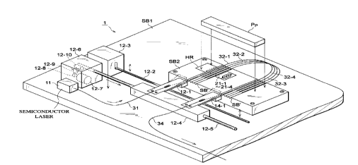
Fig. 16 is a perspective view showing an optimal
example of the above-mentioned wavelength-variable light
source 1. This wavelength-variable light source 1
23
CA 02227937 1998-O1-26
SEI 97-39
corresponds to a detailed view of that shown in Fig . 7 . Onto
a base substrate SB1, a mounting table SB2 is secured.
Optical fibers 32-1 to 32-4 are respectively disposed within
V-shaped grooves SB' formed on the surface of the mounting
table SB2 and are pressed against the mounting table SB2
by a pressure plate Pp. Disposed below diffraction gratings
21-1 to 21-4 of the respective optical fibers is a heater
HR as a physical quantity changing means. When the
diffraction gratings 21-1 to 21-4 are heated by the heater
HR, their temperature changes, thereby varying reflection
wavelength. Optical fibers 31 and 34 obliquely pass through
openings of cantilever-shaped elastic members 12-landl4-1,
each of which has one end secured onto a supporting member
12-4, respectively, whereby their tip portions are pressed
into their corresponding V-shaped grooves SB' due to elastic
forces of the elastic members 12-1 and 14-1. A lift bar 12-2
is disposed between the elastic members 12-1 and 14-1 and
the base substrate SBl. When the lift bar 12-1 is moved up
by vertical moving mechanisms 12-3 (one of which is not
depicted) respectively supporting both end portions of the
lift bar 12-2, the elastic members 12-1 and 14-1 flex upward,
whereby both the optical fibers 31 and 34 leave the V-shaped
grooves SB'.
Here, when a supporting rod 12-5 secured to the
supporting member 12-4 is moved in a direction orthogonal
to the longitudinal direction of the V-shaped grooves SB'
24
CA 02227937 1998-O1-26
SEI 97-39
by means of a horizontal moving mechanism 12-6, the fibers
31 and 34 are moved. After they are moved as desired, the
lift bar 12-2 is moved down so that the fibers 31 and 34
are placed within different V-shaped grooves SB', thus
5. terminating switching. Here, though the horizontal moving
mechanism 12-6 may be configured in various manners, a
rotary driving force of a stepping motor 12-7 is transmitted
to a worm gear 12-10 via gears 12-8 and 12-9, and this rotary
movement is transformed by the worm gear 12-10 into a
horizontal movement by which the supporting rod 12-5 is
moved horizontally. An end portion of the supporting rod
12-5 is formed with tooth flanks, which are in mesh with
the worm gear 12-10.
When this wavelength-variable light source is applied
to the OTDR apparatus 200 shown in Fig. 14, the controller
501 regulates the moving mechanisms 12-3 and 12-6 upon
switching as mentioned above. Further, the controller
(control means) 501 regulates the heater HR so as to vary
- the reflection wavelengths of the light-waveguide-type
diffraction gratings 21-1 to 21-4 . Namely, since the branch
devices 600 and 700 have temperature characteristics, there
may be cases where their transmission wavelength varies
depending on temperature, whereby backscattering light from
a point ahead of these devices cannot fully be detected.
Therefore, in the OTDR apparatus in accordance with this
embodiment, in the case where the backscattering light
CA 02227937 1998-O1-26
SEI 97-39
intensity from a position within the system to be measured
by the photodetector 500 ahead of a specific position, i.e.,
ahead of the position where the branch devices 600 and 700
are located, becomes lower than a predetermined level, the
heater HR as the physical quantity changing means is
controlled so as to change the reflection wavelengths of
the light-waveguide-type diffraction gratings2l-1 to21-4.
In other words, as shown in Fig. 17, for example, when
the branch devices 600 and 700 exist at a specific position
X, the backscattering light intensity decreases at this
position X. The intensity of backscattering light from a
position ahead of this position X is lower than that at the
position X where the branch devices 600 and 700 exist. When
the transmission wavelength characteristics of the branch
devices 600 and 700 greatly deviate from their designed
values depending on temperature, light fails to be fully
transmitted therethrough, whereby the backscattering light
intensity from a position ahead of this position X becomes
lower than a predetermined level (as indicated by dotted
line in the drawing). In such a case, the controller 501
regulates the physical quantity changing means HR so as to
slightly change the wavelength of light outputted from the
wavelength-variable light source 1, such that thus
outputted light is efficiently transmitted through the
branch devices 600 and 700. Namely, the controller 501
controls the physical quantity changing means HR so that
26
CA 02227937 1998-O1-26
SEI 97-39
the backscattering light intensity from the predetermined
position X within the system to be measured is maximized.
Alternatively, as the physical quantity changing means HR,
pressure-applying means such as piezoelectric device may
be employed as well. Further, while the controller 501
controls, when the intensity of backscattering light from
a position ahead of the position X remarkably decreases so
that it becomes lower than a predetermined level, the
physical quantity changing means HR so as to vary the
reflection wavelength of the diffraction grating; in the
case where the backscattering light intensity from the
predetermined position X does not increase even when the
reflection wavelength is thus varied, the controller 501
judges that there is abnormality in the branch devices 600
and 700, and causes the display 502 to indicate this state.
As stated above, in the wavelength-variable light
sources according to the above embodiments, light-
waveguide-type diffraction gratings are disposed in
parallel and, they are switched by an optical switch or the
like, whereby it can vary the predetermined wavelength
although the configuration is simple and inexpensive.
Further, the wavelength-variable light sources according
to the above embodiments are useful as a light source for
a WDM communication. Further, in the wavelength-variable
light sources according to the above embodiments, variation
of temperature at a specif is point in a system can be measured
27
CA 02227937 1998-O1-26
SEI 97-39
by monitoring backscattering light from the specific point
while controlling the reflection wavelength of its
diffraction grating, therefore, feedback of light different
from observation light such as communication light can be
achieved. -
The present invention is configured such that
light-waveguide-type diffraction gratings are disposed in
parallel and, while they are switched by an optical switch
or the like, a predetermined wavelength of light is
oscillated, whereby a wavelength-variable light source
having a simple configuration can be obtained
inexpensively.
Also, since the oscillation wavelength and its
band is determined by the reflection wavelength of a
light-waveguide-type diffraction grating and can be
controlled by the optical length between the semiconductor
light-emitting device and the light-waveguide-type
diffraction grating, the oscillation wavelength band can
be minutely adjusted. -
From the invention thus described, it will be
obvious that the invention may be varied in many ways . Such
variations are not to be regarded as a departure from the
spirit and scope of the invention, and all such
modifications as would be obvious to one skilled in the art
are intended for inclusion within the scope of the following
claims.
28