Sélection de la langue

Search

Sommaire du brevet 2228194 

Énoncé de désistement de responsabilité concernant l'information provenant de tiers

Une partie des informations de ce site Web a été fournie par des sources externes. Le gouvernement du Canada n'assume aucune responsabilité concernant la précision, l'actualité ou la fiabilité des informations fournies par les sources externes. Les utilisateurs qui désirent employer cette information devraient consulter directement la source des informations. Le contenu fourni par les sources externes n'est pas assujetti aux exigences sur les langues officielles, la protection des renseignements personnels et l'accessibilité.

Disponibilité de l'Abrégé et des Revendications

L'apparition de différences dans le texte et l'image des Revendications et de l'Abrégé dépend du moment auquel le document est publié. Les textes des Revendications et de l'Abrégé sont affichés :

  • lorsque la demande peut être examinée par le public;
  • lorsque le brevet est émis (délivrance).
(12) Demande de brevet: (11) CA 2228194
(54) Titre français: DISPOSITIF DE VERROUILLAGE DE PENE ACTIVE PAR UN INCENDIE
(54) Titre anglais: BOLT CLOSURE MAINTENANCE FOR FIRE-DEGRADED LATCHING ASSEMBLY
Statut: Réputée abandonnée et au-delà du délai pour le rétablissement - en attente de la réponse à l’avis de communication rejetée
Données bibliographiques
(51) Classification internationale des brevets (CIB):
  • E05C 19/00 (2006.01)
  • E05B 15/00 (2006.01)
  • E05B 65/10 (2006.01)
(72) Inventeurs :
  • UYEDA, ALAN K. (Etats-Unis d'Amérique)
(73) Titulaires :
  • ADAMS RITE MANUFACTURING CO.
(71) Demandeurs :
  • ADAMS RITE MANUFACTURING CO. (Etats-Unis d'Amérique)
(74) Agent: GOWLING WLG (CANADA) LLP
(74) Co-agent:
(45) Délivré:
(22) Date de dépôt: 1998-01-28
(41) Mise à la disponibilité du public: 1998-08-18
Requête d'examen: 2002-04-15
Licence disponible: S.O.
Cédé au domaine public: S.O.
(25) Langue des documents déposés: Anglais

Traité de coopération en matière de brevets (PCT): Non

(30) Données de priorité de la demande:
Numéro de la demande Pays / territoire Date
08/802,435 (Etats-Unis d'Amérique) 1997-02-18

Abrégés

Abrégé français

Verrou de porte comprenant : un pêne; un dispositif de déplacement permettant de faire pivoter le pêne d'une position déverrouillée à une positIon verrouillée; et un dispositif, logé dans une partie du verrou résistante au feu, qui réagit à une augmentation de température, lorsque celle-ci atteint une valeur T, en se déplaçant de manière à bloquer le pêne pour l'empêcher de passer à la position déverrouillée.


Abrégé anglais


In a door closure assembly, the combination
comprising a latch bolt element; carrier structure to
carry the bolt element to pivot between door unlatched
and latched position; and means carried by a fire
resistant portion of the assembly to be responsive to
an increase in temperature to a level T to move into
position to block door unlatching movement of the bolt
element from door latching position.

Revendications

Note : Les revendications sont présentées dans la langue officielle dans laquelle elles ont été soumises.


I CLAIM:
1. In a door closure assembly, the
combination comprising
a) a latch bolt element,
b) carrier structure to carry the bolt
element to pivot between door unlatched and latched
position,
c) and means carried by a fire resistant
portion of said assembly to be responsive to an
increase in temperature to a level T to move into
position to block door unlatching movement of said bolt
element from door latching position.
2. The combination of claim 1 wherein said
means is carried by one of the following:
- said carrier structure
- said bolt.
- 10 -

3. The combination of claim 1 wherein said
carrier structure includes a metallic plate and a
metallic sub-cover carried by the plate, said means
carried by said sub-cover.
4. The combination of claim 1 wherein said
means includes a blocking part urged in a direction of
movement of said part into blocking relation to bolt
pivoting toward unlatched position, and a meltable
element preventing said movement of said part until the
temperature of said meltable element rises to
temperature T causing melting of said element.
5. The combination of claim 4 wherein said
meltable element is positioned to obstruct said
movement of the blocking part.
6. The combination of claim 5 wherein said
means includes a spring urging said blocking part in
said direction.
- 11 -

7. The combination of claim 4 wherein said
blocking part comprises a plunger movable endwise in a
chamber, in said direction, said meltable element also
positioned in said chamber.
8. The combination of claim 7 wherein said
plunger has a flange and a blocking shank projecting in
said direction beyond said flange, and said meltable
element is positioned to extend about said shank in the
endwise path of movement of said flange.
9. The combination of claim 7 wherein said
means includes a spring in said chamber urging said
blocking part in said direction.
10. The combination of claim 9 including a
cap associated with said chamber and retaining said
spring in said chamber.
- 12 -

11. The combination of claim 9 wherein said
plunger has a bore into which said spring extends.
12. The combination of claim 1 wherein said
means is carried by said carrier structure.
13. The combination of claim 6 wherein said
means is carried by said carrier structure, which
comprises a sub-cover.
14. The combination of claim 1 wherein said
means is carried by said bolt.
15. The combination of claim 6 wherein said
means is carried by said bolt.
16. The combination of claim 14 wherein said
means comprises two blocking plungers, located at
opposite ends of the bolt.
- 13 -

Description

Note : Les descriptions sont présentées dans la langue officielle dans laquelle elles ont été soumises.

CA 02228194 1998-01-28
BACRGROUnnD OF THE lNVh~.LlON
This invention relates generally to latches,
and more particularly to mechanism operable to retain a
latch in door closed locking position as during a fire.
There is need for a small sized, compact,
easily installed mechanism which will prevent opening
of a door as during a fire. Such opening would
otherwise enable spread of the fire. Such a device
should not prevent normal opening and closing of the
door, but should only come into operation when ambient
temperature rises to a selected level T. The door may
be latched and unlatched as by electrically operated
mechanism as described in U.S. Patent 4,986,584,
incorporated herein by reference.
S~5ARY OF THE INVENTION
It is a major object of the invention to
provide improved mechanism meeting the above need.
Basically, such mechanism comprises:
a) a latch bolt element,
b) carrier structure to carry the bolt
element to pivot between door unlatched and latched

CA 02228194 1998-01-28
positions,
c) and means carried by a fire resistant
portion of the assembly to be responsive to an increase
in temperature to a level T to move into position to
block door unlatching movement of the bolt element from
door latching position.
It is a further object of the invention to
provide such means in the form of a blocking part urged
in a direction of movement of the part into blocking
relation to bolt pivoting toward unlatched position,
and a meltable or fusible element preventing movement
of the blocking part until the temperature of the
meltable element rises to temperature T causing melting
of the element. As will be seen, the meltable element
lS is typically positioned to obstruct such movement of
the blocking part, and a spring is provided to urge the
blocking part in its movement direction.
Another object of the invention is to provide
the blocking part in the form of a plunger movable
endwise in a chamber, in said direction, the meltable
element also positioned in the chamber. The plunger
may advantageously have a flange and a blocking shank
projecting in said direction beyond said flange, and
the meltable element is positioned to extend about the

CA 02228194 1998-01-28
shank in the endwise path of movement of the flange.
The plunger may itself have a bore to receive the
spring, providing a very compact assembly.
Yet another object is to support the plunger
and meltable element in a chamber formed by a sub-cover
carried as by a door frame; or, alternatively, to
support the plunger and meltable element in a chamber
formed by the bolt.
These and other objects and advantages of the
invention, as well as the details of an illustrative
embodiment, will be more fully understood from the
following specification and drawings, in which:
DRAWING DESCRIPTION
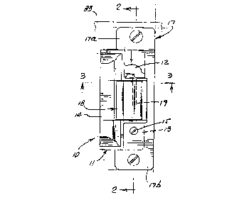
Fig. 1 is an elevation showing a bolt that is
pivotable relative to a sub-cover;
Fig. 2 is a vertical section taken on lines
2-2 of Fig. 1;
Fig. 3 is an enlarged section taken on lines
3-3 of Fig. 1;
Fig. 4 is a view like Fig. 3, showing the
bolt in unlatched position;

CA 02228194 1998-01-28
Fig. S is an enlarged section taken on lines
5-5 of Fig. 2;
Fig. 6 is like Fig. 6, but showing the
plunger in bolt blocking position;
Fig. 7 is a view like Fig. 1, showing a
modification; and
Figs. 8 and 9 are like Figs. 5 and 6, but
showing modifications.
DETAILED DESCRIPTION
As shown in Figs. 1 and 2, device 10 includes
a latch carrier such as sub-cover 11 having upper and
lower walls 12 and 13, integral with wall 14. The sub-
cover is attached as by fasteners 15 and 16 to a
mounting plate 17. The plate may have flanges or tabs
17a and 17b to be attached as by fasteners 81 to a wall
such as door frame 82. A vertically elongated strike
bolt 18 is pivotally attached to the sub-cover as by a
vertically elongated pin 19 received through an opening
in bolt flange or flanges 18c seen in Figs. 3 and 4.
Opposite ends of the pin are retained in openings 20
and 21 in sub-cover flanges lla and 11_ (see Fig. 2),
whereby the bolt pivots about the vertical axis of the

CA 02228194 1998-01-28
pin between locked condition as seen in Fig. 3, and
unlocked condition as seen in Fig. 4.
In locked condition, the hook 18b of the bolt
overlaps a part 22 in a door 23 to prevent swinging of
the door in a direction 24. In inwardly swung,
retracted bolt position, as seen in Fig. 4, the overlap
of the hook 18_ and part 22 is removed, so that the
door can then swing in direction 24. A torsion spring
is typically wrapped about pin 19 to yieldably urge the
bolt toward locked position as seen in Figs. 1-3. One
arm of the spring bears against the sub-cover and the
other arm ears against the bolt. See Fig. 7 in U.S.
Patent 4,986,584 incorporated herein by reference.
Means are typically provided to release the
strike bolt for pivoting about the axis of pin 19 for
between locked and unlocked positions, as referred to.
See said U.S. Patent 4,986,584. Element 83 represents
said bolt moving structure.
As referred to, means is provided to be
responsive to an increase in temperature (as to a level
T) to move into position to block door unlatching
movement of the bolt element from door latching
position. Such means may advantageously include a
blocking part urged in a direction of movement of the

CA 02228194 1998-01-28
blocking part into blocking relation to bolt pivoting
toward unlatched position, and a meltable or fusible
element preventing such movement of the part until the
temperature of the meltable element rises to
temperature T, causing melting of that element.
Referring to Fig. 5, a blocking part 26 and a
meltable element 27 are shown as located in a chamber
such as a bore 28 in the sub-cover 11. The part 26 has
the form of a plunger movable endwise in the direction
of axis 29. The part 26 has a guide flange 26a in
sliding engagement with bore 28, and a reduced diameter
bolt blocking shank 26b projecting in the direction of
axis 29, beyond flange 26c. This provides a
cylindrical space between the shank and the bore, in
Fig. 5, for reception of the meltable element 27
extending in obstructing relation to forward movement
of the plunger flange in direction 30. The shank 26b
has sliding engagement with a reduced diameter bore
28a, and a step shoulder 31 between bores 28 and 28a
preventing forward movement of the meltable element 27.
A coil spring 33 in the chamber defined by
bore 28 is compressed to urge the blocking part 26
forwardly, flange 26a then pressing against the
meltable element 27. Element 27 has the form of a

CA 02228194 1998-01-28
sleeve extending about shank 26a, as shown. The spring
extends within a bore 36 in the plunger, to bear
against end wall 26c. The upper end of the spring is
captivated by end wall 37a of a cap 37 secured at 38 to
an upwardly protruding portion 39 of the sub-cover.
In Fig. 5, the plunger shank 26_ is held in
upwardly retracted position by the meltable element 27,
whereby the bolt 18 may swing between door latching and
unlatching positions, as in Figs. 3 and 4. However, if
the ambient temperature rises above a selected elevated
level T, as during a fire, the element 27 fuses or
melts, and drains from its position shown in Fig. 5,
thereby allowing the plunger 26 to be displaced
downwardly to Fig. 6 position, blocking door unlatching
movement of the bolt. See also Fig. 3 showing plunger
shank 26_ moved downwardly adjacent the side wall 18_
of the bolt, and in offset relation to the pivot pin
19, as shown. At this time, plunger flange 26a engages
the step shoulder 31.
The meltable element may consist of lead,
for example, and may drain from Fig. 5 position as via
a drain passage 39 in the sub-cover. The sub-cover
itself, and the bolt, normally consist of a metal such
as steel that does not fuse or melt at temperature T or

CA 0222X194 1998-01-28
temperatures close to T. An example of temperature T
is 350 to 450~F.
Figs. 7-9 show a modified form of the
invention, in which the plunger 26~ and meltable
element 27' are carried in a bore 28' in the bolt 18'.
Spring 33' urges the plunger upwardly, the plunger
flange 26a' sliding in bore 28~ and pressing against
the retained meltable element 27' when the temperature
reaches T, element 27' melts and drains out of
obstructing relation to plunger movement. See for
example drain passage 39' in the bolt and extending to
an outer side of the bolt. The plunger is then
displaced upwardly, so that its shank 26k' enters an
opening 45 in the sub-cover 11', as shown in Fig. 9,
thereby blocking swinging movement of the bolt in its
door latching position. Fig. 7 shows use of two
blocking elements 26', at upper and lower ends of the
bolt, to engage in openings 45 in sub-cover flanges lla
and llk.

Dessin représentatif
Une figure unique qui représente un dessin illustrant l'invention.
États administratifs

2024-08-01 : Dans le cadre de la transition vers les Brevets de nouvelle génération (BNG), la base de données sur les brevets canadiens (BDBC) contient désormais un Historique d'événement plus détaillé, qui reproduit le Journal des événements de notre nouvelle solution interne.

Veuillez noter que les événements débutant par « Inactive : » se réfèrent à des événements qui ne sont plus utilisés dans notre nouvelle solution interne.

Pour une meilleure compréhension de l'état de la demande ou brevet qui figure sur cette page, la rubrique Mise en garde , et les descriptions de Brevet , Historique d'événement , Taxes périodiques et Historique des paiements devraient être consultées.

Historique d'événement

Description Date
Inactive : CIB de MCD 2006-03-12
Demande non rétablie avant l'échéance 2005-01-28
Le délai pour l'annulation est expiré 2005-01-28
Réputée abandonnée - omission de répondre à un avis sur les taxes pour le maintien en état 2004-01-28
Lettre envoyée 2002-05-29
Modification reçue - modification volontaire 2002-04-15
Requête d'examen reçue 2002-04-15
Toutes les exigences pour l'examen - jugée conforme 2002-04-15
Exigences pour une requête d'examen - jugée conforme 2002-04-15
Demande publiée (accessible au public) 1998-08-18
Inactive : CIB attribuée 1998-05-27
Inactive : CIB en 1re position 1998-05-27
Symbole de classement modifié 1998-05-27
Modification reçue - modification volontaire 1998-05-08
Inactive : Certificat de dépôt - Sans RE (Anglais) 1998-04-22
Demande reçue - nationale ordinaire 1998-04-22

Historique d'abandonnement

Date d'abandonnement Raison Date de rétablissement
2004-01-28

Taxes périodiques

Le dernier paiement a été reçu le 2003-01-13

Avis : Si le paiement en totalité n'a pas été reçu au plus tard à la date indiquée, une taxe supplémentaire peut être imposée, soit une des taxes suivantes :

  • taxe de rétablissement ;
  • taxe pour paiement en souffrance ; ou
  • taxe additionnelle pour le renversement d'une péremption réputée.

Les taxes sur les brevets sont ajustées au 1er janvier de chaque année. Les montants ci-dessus sont les montants actuels s'ils sont reçus au plus tard le 31 décembre de l'année en cours.
Veuillez vous référer à la page web des taxes sur les brevets de l'OPIC pour voir tous les montants actuels des taxes.

Historique des taxes

Type de taxes Anniversaire Échéance Date payée
Taxe pour le dépôt - générale 1998-01-28
Enregistrement d'un document 1998-01-28
TM (demande, 2e anniv.) - générale 02 2000-01-28 1999-12-07
TM (demande, 3e anniv.) - générale 03 2001-01-29 2000-12-20
TM (demande, 4e anniv.) - générale 04 2002-01-28 2001-12-17
Requête d'examen - générale 2002-04-15
TM (demande, 5e anniv.) - générale 05 2003-01-28 2003-01-13
Titulaires au dossier

Les titulaires actuels et antérieures au dossier sont affichés en ordre alphabétique.

Titulaires actuels au dossier
ADAMS RITE MANUFACTURING CO.
Titulaires antérieures au dossier
ALAN K. UYEDA
Les propriétaires antérieurs qui ne figurent pas dans la liste des « Propriétaires au dossier » apparaîtront dans d'autres documents au dossier.
Documents

Pour visionner les fichiers sélectionnés, entrer le code reCAPTCHA :


Pour visualiser une image, cliquer sur un lien dans la colonne description du document (Temporairement non-disponible). Pour télécharger l'image (les images), cliquer l'une ou plusieurs cases à cocher dans la première colonne et ensuite cliquer sur le bouton "Télécharger sélection en format PDF (archive Zip)" ou le bouton "Télécharger sélection (en un fichier PDF fusionné)".

Liste des documents de brevet publiés et non publiés sur la BDBC .

Si vous avez des difficultés à accéder au contenu, veuillez communiquer avec le Centre de services à la clientèle au 1-866-997-1936, ou envoyer un courriel au Centre de service à la clientèle de l'OPIC.

({010=Tous les documents, 020=Au moment du dépôt, 030=Au moment de la mise à la disponibilité du public, 040=À la délivrance, 050=Examen, 060=Correspondance reçue, 070=Divers, 080=Correspondance envoyée, 090=Paiement})


Description du
Document 
Date
(aaaa-mm-jj) 
Nombre de pages   Taille de l'image (Ko) 
Dessin représentatif 1998-08-30 1 6
Abrégé 1998-01-27 1 12
Revendications 1998-01-27 4 66
Description 1998-01-27 8 215
Dessins 1998-01-27 4 92
Description 2002-04-14 8 217
Revendications 2002-04-14 2 66
Dessins 1998-05-07 6 103
Courtoisie - Certificat d'enregistrement (document(s) connexe(s)) 1998-04-21 1 117
Certificat de dépôt (anglais) 1998-04-21 1 163
Rappel de taxe de maintien due 1999-09-28 1 114
Accusé de réception de la requête d'examen 2002-05-28 1 179
Courtoisie - Lettre d'abandon (taxe de maintien en état) 2004-03-23 1 175
Taxes 2003-01-12 2 54
Taxes 2001-12-16 1 28
Taxes 1999-12-06 1 30
Taxes 2000-12-19 1 29