Note : Les descriptions sont présentées dans la langue officielle dans laquelle elles ont été soumises.
CA 02231166 1998-03-03
W O 97/11340 PCT~L96/00102
MET~OD AND APPARATUS FOR TRUE TEMPERATURE DETERMINATION
FIELD OF THE l~V~llON
The present invention relates generally to optical
pyrometry and, more particularly, to determination of
temperature deviations during process monitoring.
BACKGROUND OF THE INVENTION
Many industrial processes require precise monitoring of
the true temperature, i.e., the thermodynamic temperature, of a
material being processed. In some processes, temperature
deviations indicate a process failure, in others, changes in
temperature and/or emissivity indicate the progression of the
monitored process. Examples of processes which require precise
temperature monitoring include: metal refining and working,
glass and glass product manufacture, firing ceramics,
integrated circuit fabrication, electricity generation,
chemical and pharmaceutical manufacture and many other
industrial processes.
It should be appreciated, that in many cases it is not
practical to measure the temperature of the processed material
directly, such as by thermocouple, due to the delicacy of the
process, the reaction speed of the temperature measurement
device or the enviromnental conditions. Rather, the temperature
is determined based on radiative emissions of the processed
material. Typically, these emissions are not directly detected,
because they must pass through an intervening medium, such as
hot air or smoke, which usually has an unknown and variable
transmission spectrum~
Several non-contact temperature measurement methods are
known in the art. Brightness pyrometry is a general name for
temperature measurement methods which determine the temperature
of an object based on the total amount of radiation emitted by
the object. Typically, only the radiation emitted in a certain
spatial direction and within a certain wavelength range is
measured. Brightness pyrometry is further described in "Traite
de Pyrometric Optique", by C. Ribaud, Paris, 1931.
~ A major limitation of brightness pyrometry is that the
determined temperature is correct only if the product of the
emissivity (~) of the object being measured and the
CA 02231166 1998-03-03
WO 97/11340 PCT~L96/00102
emissivity (~) of the object being measured and the
transmission spectrum of the intervening medium (~), is known
at each measurement time.
Color-ratio pyrometry is a general name for temperature
determination methods which determine the temperature based on
the ratio between the intensity of light emitted at first
wavelength and the intensity of light emitted at a second
wavelength. This pyrometric technique is further described in
"Traite de Pyrometric Optique", cited above, in "Optishe
Pyrometrie", by F. Hoffman and C. Tingwaldt, published by
Braunschweig, 1938 and in "Some Consideration of Error of
Brightness and Two-Color Types Spectral Radiation Pyrometers",
by E.S. Pyatt, in British AppLied Physics, Vol. 15, No. 5, pp.
264-268, 1954.
High accuracy of temperature determination using the
color-ratio pyrometric method can only be achieved in cases
where the product of the emissivity and the medium transmission
spectrum is constant or gray and does not change with respect
to time or wavelength. The value of the product does not need
to be known. In order to overcome this limitation, an advanced
method, described in "High Speed Radio Pyrometry", by G.A.
Hornbeck, in a symposium on "Temperature, its Measurement and
Control in Science and Industry", Vol. 3, p. 2425, New York,
1962, "A Review of Multicolor Pyrometry for Temperatures Below
1500 ~C", by P.M. Reynolds, in British Applied Physics, Vol. 15
pp. 579-589, 1964, and in "Measurement True Temperature Real-
Bodies, Methods and Apparatus Optical Pyrometry", by E.D.
Glazman and I.I. Novikov in Science 1983, pp. 21-27, Moskva
1983 (in Russian), uses the ratios of the intensities of three
or four wavelengths. In the three wavelength method, the
requirement for a high accuracy of the result is that ~ ,T) *
~(~3, T) c ~ (A2,T), where ~i is the wavelength and T is the true
temperature of the object. In the four wavelength method, the
requirement for a high accuracy of the results is that ~(~l,T)
* ~(~4,T) = ~(~2,T) * ~(~3,T)-
CA 02231166 1998-03-03
W O 97/11340 PCT~L96/00102
Another pyrometric method, multi-wavelength pyrometry, is
a general name for temperature measurement methods which:
(a) determine the apparent temperature at several
wavelengths using one of the abovedescribed pyrometric methods;
and
(b) estimate the true temperature based on a model of the
dependency of emissivity on wavelength.
Multi-wavelength techniques are further described in
"Determination of Emissivity of a Substance from the Spectrum
of its Thermal Radiation and Optimal Methods of Optical
Pyrometry", by D.Y. Swet, in "High Temperatures-High
Pressures", Vol. 8, pp. 493-498, 1976, "Multi-Wavelength
Pyrometry", by P.B. Coates, in Metrology, No. 17, pp. 103-109,
1981 and "Noncontact Temperature Measurement 1, Interpolation
Based Techniques", by M.A. Khan, C. Allemand and T.W. Eagar, in
Rev. Sci. Instrum., 62(2), pp. 392-402, 1991 the disclosures of
which are incorporated herein be reference.
A limitation of multi-wavelength pyrometric techniques is
that in many cases the differences between the measured
temperatures can be explained by more than one emissivity
model, so the true temperature cannot be determined without a
correct model. It should be noted that in several applications
satisfactory results have been achieved using a simple model.
Some approximation methods suitable for multi-wavelength
pyrometry are described in "Determination of Emissivity",
"Multi-Wavelength Pyrometry" and "Noncontact Temperature
Measurement", cited above. However, these methods are only
useful when the dependence of the emissivity on the wavelength
is generally known. Otherwise, the error in the true
temperature determination may very well be larger than the
error in true temperature determination using one of the first
two abovedescribed pyrometric techniques.
A major limitation of most known pyrometric techniques is
their inability to deal with changes in emissivity, in
particular, where such changes cannot be anticipated in
advance.
CA 02231166 1998-03-03
WO 97/11340 PCT~L96/00102
SUMU~ARY OF THE l~V~:N~llON
It is an object of some aspects of the present invention
to provide a method of pyrometry capable of accurate
measurements of the true temperature of a body even where the
emissivity varies with time and/or wavelength.
It is another object of some aspects of the present
invention to provide a pyrometric method whose accuracy is not
substantially affected by changes in a medium interposed
between a pyrometer and the measured body.
It is still another object of some aspects of the present
invention to provide a pyrometric method having a high
accuracy, preferably over 1~.
It is a further object of some aspects of the present
invention to provide a pyrometric method capable of receiving
an accuracy-enhancing input in the form of emissivity values.
It is a still further object of some aspects of the
present invention to provide a method of measuring the varying
emissivity of an object. Further, In some embodiments of the
present invention, the true temperature of the object can be
used to enhance the accuracy of the measured emissivities.
It is yet another object of some aspects of the present
invention to provide a method of monitoring physical parameters
of a industrial process, such as temperature, crystallization
state and chemical composition, and to provide feedback when
the process exceeds certain limits.
In a preferred embodiment of the present invention a
method of true temperature determination of an object includes:
(a) measuring radiative emissions from the object;
(b) determining at least one characteristic of the
emissions;
(c) finding a match between the determined characteristic
and a plurality of characteristics; and
(d) calculating the true temperature of the object based
on at least one value associated with each of the plurality of
characteristics.
Preferably, the radiative emissions are measured at a
plurality of discrete wavelengths. Preferably, less than twenty
wavelengths are used, more preferably, less than ten and most
_
CA 02231166 1998-03-03
W O 97/11340 PCT~L96/00102
preferably, less than six wavelengths are used in preferred
embodiments of the invention.
A preferred characteristic of radiative emissions is a
vector in which each component is indicative of a functional
relationship between emissions at at least two different
wavelengths. Preferably, each component is the difference
between the reciprocals of brightness temperatures. The
brightness temperatures are determined by applying the
brightness temperature determination method on the measured
emissions.
Preferably the values associated with each characteristic
are correction factors for correcting imprecisely determined
temperatures, preferably emissivities. Thus, one of the
brightness temperatures can be corrected to reflect the true
temperature using these correctional factors. Alternatively,
correction factors can be used to correct a color-ratio
temperature.
The calibration of a device according to a preferred
embodiment of the present invention comprises:
(a) measuring radiative emissions from the object;
(b) determining a correction value to correct a
temperature determined using the emissions to the true
temperature of the object; and
(c) storing the measured radiative emissions along with
the determined correctional value or the true temperature.
In one preferred embodiment the true temperature is
determined using a thermocouple. In another preferred
embodiment, the true temperature is determined by an input of
the emissivity. The emissivity is used to correct one of the
determined temperatures. In yet another preferred embodiment,
the true temperature is estimated to be equal to a previously
determined temperature, at least for determining the correction
factor. In such a case, the current true temperature is
estimated by correcting one of the temperatures determined from
the radiative emissions using the thus derived correction
factor.
CA 02231166 1998-03-03
W O 97/11340 PCT~L96/00102
There is therefore provided in accordance with a preferred
embodiment of the present invention, a method of true
temperature determination of an object including:
(a) acquiring radiation emitted by an object at a
plurality of wavelengths;
(b) determining a characteristic of the acquired radiation
which is based on a relationship between radiative emissions
acquired at more than one wavelength;
(c) determining a factor related to an error, using the
characteristic; and
(d) calculating a current temperature of the object based
on the correctional factor.
Preferably, determining a factor includes:
attempting to match the determined characteristic with a
plurality of stored characteristics to find a matched
characteristic; and
retrieving a factor associated with the matched
characteristic.
Preferably, determining a factor further includes:
determining a new factor based on the acquired radiation
and on a previously acquired temperature if the matching
attempt fails; and
storing the determined characteristic in association with
the new factor or with the previously acquired temperature, if
the matching attempt fails.
In a preferred embodiment of the invention where the
determined characteristic and the plurality of stored
characteristic are vectors, attempting to match preferably
includes:
choosing a stored vector; and
determining if each component in the deter~ne~
characteristic is within 3% of its corresponding component of
the stored vector.
Alternatively or additionally, calculating includes:
determining a temperature based on the acquired radiation,
where the determined temperature has an error related to the
factor; and
CA 02231166 1998-03-03
W O 97/11340 PCT~L96/00102
correcting the error in the determined temperature using
the factor. Preferably, the determined temperature is a
brightness temperature.
Alternatively or additionally, the factor is a vector of
values indicating at least one emissivity value.
In a preferred embodiment of the invention where the
determined characteristic is a vector, determining a
characteristic preferably includes:
converting radiation acquired at each of the plurality of
wavelengths into a brightness temperature; and
defining each component of the determined characteristic
as a reciprocal of the difference between the brightness
temperatures of two wavelengths.
Preferably, the plurality of wavelengths is fewer than
twenty wavelengths. Further preferably, the plurality of
wavelengths is fewer than ten wavelengths. Most preferably, the
plurality of wavelengths is fewer than six wavelengths.
In one preferred embodiment of the invention, radiation
emitted by the object is acquired through an interposing medium
with a variable transmission spectrum.
There is further provided in accordance with a preferred
embodiment of the invention, a method of calibrating a multi-
wavelength pyrometer including:
(a) acquiring radiation emitted by an object at a
plurality of wavelengths;
(b) determining a characteristic of the acquired radiation
which is based on a relationship between radiative emissions
acquired at more than one wavelength;
(c) estimating a current temperature of the object;
(d) determining a factor related to a discrepancy between
the current temperature and a temperature determined from the
radiative emissions; and
(e) storing the determined characteristic in association
with the correctional factor or the current temperature.
Preferably, estimating a current temperature includes
determining a temperature from the acquired radiation using a
measured emissivity. Alternatively, estimating a current
temperature includes determining a temperature from the
CA 02231166 1998-03-03
W O 97/11340 PCTnL96/00102
acquired radiation using a stored emissivity. Alternatively,
estimating a current temperature includes directly measuring
the temperature. Alternatively, estimating a current
temperature includes utilizing a previously determine~
temperature. Alternatively, estimating a current temperature
includes estimating a current temperature and a current
emissivity from the acquired radiation and from a previously
determined emissivity. Preferably, the method includes
determining an emissivity from a directly measured temperature
and the acquired radiation.
Preferably, storing the determined characteristic
includes:
attempting to match the determined characteristic with
previously stored characteristics; and
storing the determined characteristic in association with
the factor or the current temperature if the matching attempt
fails.
In a further preferred embodiment of the invention, where
the characteristics are vectors, attempting to match preferably
includes:
choosing a stored vector; and
determining if each component in the determined
characteristic is within 3~ of its corresponding component of
the stored vector.
Preferably, the method includes repeating (a)-(e) until
the percentage of successful matches over a predetermined
number of measurements is above a predetermined value.
Preferably, the factor is a vector of values indicating at
least one emissivity value.
In a preferred embodiment of the invention, where the
determined characteristic is a vector, determining a
characteristic preferably includes:
converting radiation acquired at each of the plurality of
wavelengths into a brightness temperature; and
defining each component of the determined characteristic
as a reciprocal of the difference between the brightness
temperatures of two wavelengths.
CA 02231166 1998-03-03
W O 97/11340 PCT~L96100102
Preferably, the plurality of wavelengths is fewer than
twenty wavelengths. Further preferably, the plurality of
wavelengths i5 fewer than ten wavelengths. Most preferably, the
plurality of wavelengths is fewer than six wavelengths.
In a preferred embodiment of the invention, radiation
emitted by the object is acguired through an interposing medium
with a variable transmission spectrum.
Preferably, the factor is based on the acquired radiation.
Preferably determining a factor includes:
determining a plurality of brightness temperatures based
on the acquired radiation; and
determining an emissivity at each wavelength which is
connected with a discrepancy between the determined current
temperature and the brightness temperature at the wavelength.
There is further provided in accordance with a preferred
embodiment of the invention, a method of true emissivity
determination including:
(a) acquiring radiation emitted by an object at a
plurality of wavelengths;
(b) determining a characteristic of the acquired radiation
which is based on a relationship between radiative emissions
acquired at more than one wavelength;
(c) determining a factor, using the characteristic; and
(e) calculating a current emissivity of the object based
on the factor.
Preferably, determining a factor includes:
attempting to match the determined characteristic with a
plurality of stored characteristics to find a matched
characteristic; and
retrieving a factor associated with the matched
characteristic.
Preferably, determining a factor further includes:
determining a new factor based on the acquired radiation
and on a previously acquired temperature if the matching
attempt fails; and
storing the determined characteristic in association with
the new factor or with the previously acguired temperature, if
the matching attempt fails.
CA 02231166 1998-03-03
W O 97/11340 PCT~L96/00102
In a preferred embodiment of the invention, where the
determined characteristic and the plurality of stored
characteristic are vectors, attempting to match preferably
includes:
choosing a stored vector; and
determining if each component in the determined
characteristic is within 3% of its corresponding component of
the stored vector.
Preferably, calculating includes:
determining a first temperature based on the ac~uired
radiation, where the first temperature has an error related to
the factor;
correcting the error in the first temperature using the
factor;
determining a second temperature based on the acquired
radiation, where the second temperature has an error related to
the emissivity of the object; and
determining the emissivity of the object at a second
wavelength based on the difference between the first
temperature and the second temperature.
Preferably, the second temperature is a brightness
temperature.
Preferably, the factor is a vector of values indicating at
least one emissivity.
In a preferred embodiment of the invention, where the
determined characteristic is a vector, determining a
characteristic preferably includes:
converting radiation acquired at each of the plurality of
wavelengths into a brightness temperature; and
defining each component of the determined characteristic
as a reciprocal of the difference between the brightness
temperatures of two wavelengths.
Preferably, the plurality of wavelengths is fewer than
twenty wavelengths. Further preferably, the plurality of
wavelengths is fewer than ten wavelengths. Most preferably, the
plurality of wavelengths is fewer than six wavelengths.
CA 02231166 1998-03-03
W O 97/11340 PCT~L96/00102
Preferably, radiation emitted by the object is acquired
through an interposing medium with a variable transmission
spectrum.
CA 02231166 1998-03-03
W O 97/11340 PCT~L96/00102
BRIEF DESCRIPTION OF THE DRAWINGS
The invention wilL be more fully understood from the
following detailed description of the preferred embodiments
thereof, taken in conjunction with the drawings in which:
Fig. 1 is a schematic partially sectioned illustration of
a side view of one implementation of a pyrometer system
utilized to measure the temperature of an object in accordance
with a preferred embodiment of the invention;
Fig. 2 is a general flowchart showing a method of true
temperature determination according to a preferred embodiment
of the invention;
Fig. 3A is a general flowchart showing a preferred method
for calibrating a true temperature determination device built
in accordance with a preferred embodiment of the invention;
Fig. 3B is a general flowchart showing an alternative
preferred method for calibrating a true temperature
determination device built in accordance with a preferred
embodiment of the invention;
Fig. 4 is a general flowchart showing another alternative
preferred method for calibrating a true temperature
determination device built in accordance with a preferred
embodiment of the invention;
Fig. 5 is a partially schematic illustration of a side
view of a true temperature determination device according to a
preferred embodiment of the invention; and
Flg. 6 is a partially schematic illustration of a side
view of a true temperature determination device according to
another preferred embodiment of the invention.
CA 02231166 1998-03-03
W O 97/11340 PCT~L96/00102
DESCRIPTION OF THE PREFERRED EMBODIMENTS OF THE lNV~hllON
Fig. 1 is a schematic partially sectioned illustration of
a side view of one implementation of a pyrometer system
utilized to measure the temperature of an object 12 in
accordance with a preferred embodiment of the invention. A
pyrometer 14 for determines the temperature of object 12, such
as molten metal disposed in a vat 10, through an intervening
medium 18. Typically in metal working situations, pyrometer 14
is protected from the environment by a transmissive plate 20,
which has a known and constant transmission spectrum. A
thermocouple 16 is optionally provided for calibration, as
described below.
A preferred embodiment of the present invention for
determining the true temperature of object 12 is based on
brightness pyrometry of object 12. If the brightness
temperature of object 12 is calculated using a black-body
model, the following formula is known to describe an error in
the determined temperature which is caused by object 12 being
gray (having an emissivity, ~ ' 1), rather than black (~ = 1)
and by the attenuating effects of intervening medium 18 and
plate 20:
~b 1= T-1_ C In(~(A,~ r(A)) (1)
where:
Tb is the determined brightness temperature of object 12;
T is the true temperature of object 12;
A is the wavelength at which the brightness temperature is
determined;
C2 is a known thermodynamic constant;
~(A,T) is the emissivity, which is a function of both the
wavelength and the temperature; and
~(A) is the transmission spectra of intervening medium 18
and plate 20.
The above equation contains three unknowns, the true
temperature, the emissivity, and the transmission spectra of
intervening medium lB and plate 20. If, however, two different
CA 02231166 1998-03-03
WO 97/11340 PCT~L96/00102
brightness temperatures of object 12 are subtracted from each
other, the difference is not directly dependent on the true
temperature of object 12, only on the emissivity of object 12
and on the transmission spectra of intervening medium 18 and
plate 20:
bl b2 (~1~A2)= C Ln(~(A2 ~ r(~2))~ I Ln(~
As can be appreciated, a single difference value R(~l~A2)
does not, by itseLf, indicate the true temperature of object 12
because there may be several temperatures at which the~0 difference between the emissivities of object 12 at wavelength
and at wavelength ~2 are the same. In addition, ~(~) i5 a
random function and as such, adds noise.
The inventor has found that if several difference values
of brightness temperatures at different wavelengths are
aggregated to form a difference vector R, this difference
vector substantially indicates a unique correction factor for
translating an erroneous brightness temperature into a true
temperature. In addition, even a vector of relatively low order
is robust enough to overcome the noise effects of T(~). A
difference vector R is preferably generated by simultaneously
measuring the brightness temperature of object 12 at a
plurality of wavelengths and setting each component of
difference vector R to the difference between the reciprocals
of two consecutive brightness temperatures.
Thus, as shown in equation (1), a brightness temperature
of object 12 can be corrected to determine the true temperature
of object 12 using the emissivity of object 12. This
emissivity, which typically cannot be accurately measured, can
be known before-hand and be associated with an R difference
vector. Thus, the true temperature of object 12 can be
determined based on the measurement of brightness temperatures
and a stored table of correction values, i.e., emissivities.
It should be appreciated that under varying conditions a
plurality of different vectors R may indicate the same true
14
CA 02231166 1998-03-03
W O 97/11340 PCT~L96/00102
temperature. For e~ample, if the emissivity of object 12
changes due to chemical changes in object 12, difference vector
R will change even though the temperature of object 12 does
not.
It should also be appreciated from equation (1), that if
the true temperature of object 12 is known or determined, the
emissivities at each of a plurality of wavelengths can be
calculated from the true temperature and the brightness
temperature at the wavelength. Conversely, if the brightness
temperature and the emissivities are known, the true
temperature can be calculated.
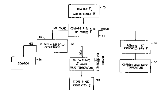
Fig. 2 is a general flowchart showing a method of true
temperature determination according to a preferred embodiment
of the invention. First, as indicated by reference number 50, a
vector Tb of brightness temperatures is determined by measuring
radiative emissions object 12 at a plurality of wavelengths and
calculating a difference vector R. The calculated vector R is
compared to a plurality of reference vectors R' stored in
pyrometer 14. If a match is found, an emissivity vector Et
stored in association with R' is retrieved (reference 54). At
least one of the brightness temperatures in Tb is corrected
(reference 56) using the retrieved emissivity vector ~', as a
correction factor in equation (1), resulting in the true
temperature. Alternatively, several brightness temperatures are
corrected and a weighted average of the corrected temperatures
is produced as the true temperature of object 12.
If no match is found, an emissivity vector ~ is calculated
62 based on R and on the last determined temperature. The
difference vector R and its associated emissivity vector ~ are
stored in pyrometer 14 for later use (as indicated by reference
numbers 52 and 54). One or two consecutive no-match situations
do not usually result in errors in the derived emissivity
vector ~, because the temperature of object 12 changes
relatively slowly. However, a run of no-match situations
usually indicates that the temperature and/or emissivity of
CA 02231166 1998-03-03
W O 97/11340 PCT~L96/00102
object 12 are changing in unanticipated ways. In this case, the
-
R vector represents an unknown situation and an error signal
is typically produced. In a multi-stage process, a different
plurality of R' vectors may be stored for each stage of the
process.
A preferred calibration method for pyrometer 14 utilizes
thermocouple 16 (Fig. 1). The calibration method is similar to
the temperature determination method described in conjunction
with Fig. 2. This calibration method is preferred where the
emissivity of object 12 changes by a substantial amount even
for small or no changes in the temperature of ob;ect 12. An
example of such a process is a volatile chemical process where
new compounds are continuously being synthesized and
decomposed, where, typically, each compound has a different
emissivity.
Typically, the calibration process is matched to a
particular process to be monitored. If a process with a defined
start and finish are monitored, a number of processes are
usually utilized to provide calibration data. If a continuous
process is to be monitored, the calibration process is
typically continued until enough calibration data is ac~uired.
A preferred method of estimating the sufficiency of the
calibration data is to determine the ratio between the number
of successful and unsuccessful matches between new R vectors
stored R' vectors, i.e., the hit rate. This hit rate can be
determined using statistical methods well known in the art. In
addition, in a multi-stage process, pyrometer 14 may be
separately calibrated for each stage.
To start the calibration process, thermocouple 16 is
placed in contact with object 12 and allowed to return a stable
reading of the temperature of object 12. After this first
measurement with thermocouple 16, thermocouple 16 is not
re~uired. Rather, the temperature of object 1~ is determined
using the method described in conjunction with Fig. 2 and the
3S calculated emissivity vector ~ is stored in association with
its R vector. It should be appreciated that in the calibration
CA 02231166 1998-03-03
W O 97/11340 PCT~L96/00102
process runs of no-match situations are perfectly acceptable
and anticipated.
Alternatively to using thermocouple 16 to determine the
true temperature, an emissivity input, as described below with
S reference to Fig. 3B, may be used to correct one of the
brightness temperatures. The corrected brightness temperature
may be used interchangeably with the thermocouple temperature.
Preferably, no clear-cut distinction is made between
calibration and usage of pyrometer 14. Rather, pyrometer is
continuously calibrated to and is adapted to the measurement
environment. When a long run of no-match situation is
encountered after a substantial amount of calibration has been
performed, an error is signal may be generated, as described
above. Typically, each process has its own minimum calibration
run and allowed length of no-match situations.
In the above described calibration and measurement methods
the technique of matching two difference vectors R and R' is
important. Preferably, a match between two vectors is defined
to be successful if each and every one of the components of one
vector is within a set percentage, such as 3%, of the
corresponding component in the other vector. Alternatively
other pattern matching methods are used, for example, two
vectors are considered to match if the ratio of the vectors'
magnitude is within a certain range.
In a further preferred embodiment of the invention, a
neural network is used to learn difference vectors R' and their
associated emissivity vectors ~'. Alternatively, calibration
information may be stored as a multi-dimensional function,
which can be determined by analyzing calibration data.
Fig. 3A is a general flowchart showing an alternative
preferred method for calibrating a true temperature
determination device built in accordance with a preferred
embodiment of the invention. Unlike the calibration method
described in association with Fig. 2, the calibration method of
Fig. 3A preferably uses thermocouple 16 throughout the
calibration. The calibration method of Fig. 3A is especially
,
CA 0223ll66 l998-03-03
W O 97/11340 PCT~L96/00102
preferred when the temperature change rate is of the same
order of magnitude as the emissivity change rate.
Calibration is initiated (reference 70) by measuring ~b
and calculating difference vector R. Emissivity vector ~ is
then calculated from difference vector R using an input 74 of
the true temperature derived from thermocouple 16 (equation 1).
If the difference vector R does not match any vector R'
that is stored in pyrometer 14, difference vector R and its
associated emissivity vector ~ are stored in pyrometer 14.
The above calibration steps are preferably repeated until
a desired matching hit-rate (of R and R' ) is reached.
In some cases it is not practical to measure the true
temperature of object 12 using any direct contact method. In
these cases, a different calibration method may be preferred.
Fig. 3B is a general flowchart show another preferred
method for calibrating a true temperature determination device
built in accordance with a preferred embodiment of the
invention. The calibration method of Fig. 3B is also suitable
for cases where the temperature change rate is similar to the
emissivity change rate. Instead of acquiring the true
temperature of object 12 using a thermocouple, the values of
the emissivity of object 12 at one of the measuring wavelengths
is used. Typically, this emissivity value is stored in a memory
bank based on a known emission profile or the emissivity may be
measured using an emissivity measurement device.
Calibration is initiated (reference 80) by measuring Tb
and calculating R therefrom. The true temperature of object 12
is then calculated (reference 82) using one of the measured
brightness temperatures of Tb and an input 84 of the emissivity
of object 12 at a specific wavelength. Where the emissivity
values are stored and not measured in real-time, the emissivity
may be stored as a table with each value corresponding to a
measured brightness temperature or alternatively each value may
be associated with a step of the monitored process, at which
the emissivity is known to change.
18
,
CA 02231166 1998-03-03
W O 97/11340 PCT~L96/00102
Emissivity vector ~ is calculated from difference vector
R using the true temperature calculated in (reference 82).
If difference vector R does not match any vector R' that
- is stored in pyrometer 14, difference vector R and its
associated emissivity vector ~ are stored in pyrometer 14.
The above calibration steps are preferably repeated until
a desired matching hit-rate (of R and R') is reached.
In some cases, it is not practical to use the calibration
methods described in reference to Fig. 3A or Fig. 3B. If the
magnitude of the temperature change rate is similar to the
magnitude of the emissivity change rate the following
calibration method may be preferred.
To start the calibration process, thermocouple 16 is
placed in contact with object 12 and allowed to return a stable
reading of the temperature of object 12. After this first
measurement with thermocouple 16, thermocouple 16 is not
required. The brightness temperature Tb of object 12 is
measured and a difference vector R is determined from
brightness temperature Tb. ~ is calculated from Tb using the
true temperature input from thermocouple 16 and is stored in
association with R. This ends a first calibration cycle, which
is similar to the caLibration cycle described in reference with
Figs. 2 and 3A. Further calibration cycles start with a
measurement of Tb and a determination of R from Tb. Both ~ and
the true temperature are assumed to have changed since the last
calibration cycle, however, T and ~new may be estimated from Tb
and a previously determined ~ by solving the following set of
equations:
19
CA 02231166 1998-03-03
WO 97/11340 PCTnL96/00102
Xbl = T - c In~l - c lnKl
Tb2 1 = F C2 1 2 C2 1 C2
(3)
bn C2 n C2 1 C2 Kl-~Al( ~ An~ n
where
. (NEW) /
/~i(OLD) ( 4
K --Ki = Ko + ~ (~l j Ai)dAn ~21
It should be noted, that if n brightness temperatures are
used, the approximation of K is of the order of n-2. Higher
orders of K are preferably assumed to be 0. If a higher number
of wavelengths are used, the accuracy of the estimation is
enhanced.
~ and R are stored, as described with reference to
the previously described calibration methods and a new
calibration cycle is started.
In the above described methods it is described to store an
emissivity vector in association with a difference vector. It
should be appreciated, that it is not necessary to store
emissivity values. Rather, what is stored is a factor which is
related to the error. For example, if the true temperature is
stored in association with the difference vector, the
emissivity values can be calculated when the true temperature
is retrieved. Thus, all that is required is that the value(s)
stored in association with the difference vector be operative
-
-
CA 02231166 1998-03-03
W O 97/11340 PCT~L96/00102
to reconstruct a corrective factor for at least one of the
measured brightness temperatures.
Fig. 5 is a schematic side view of a pyrometer 90
according to a preferred embodiment of the invention. Radiative
emissions are emitted by object 12, pass through intervening
material 18 and are detected by a radiation detector 100 which
-generates signals corresponding to the impinging radiation.
Preferably, a lens 92 and an iris 94 are used to direct a
portion of the radiative emissions to detector 100.
Alternatively or additionally, another type of wave guide is
used, such as a high emissivity tube or a tube constructed of a
material with a high reflectivity. The choice between the wave
guiding method preferably depends on the size of the portion of
object 12 being measured and the amount of reflections in the
measurement area.
As described hereinabove, the true temperature of obiect
12 is determined from a plurality of brightness temperatures,
each of which is measured at a different wavelength. In a
preferred embodiment of the invention, a multi-filter chopper
wheel 98, having a plurality of color filters 102, selectably
filters the radiative emissions so that only radiation of a
narrow wavelength reaches detector 100 at a time. In a
preferred embodiment of the invention, four filters, having
transmission wavelengths of 0.7~, 0.8~, 0.9~ and 1~, for
ZS example, are used. The transmission spectra of each filter is
preferably about 10 nanometers wide, although narrower or
broader spectral widths can be used. Preferably, filters 102
are circumferentially arranged around of wheel 98 and a motor
104 spins wheel 98 so that at any instant only one of filters
102 is disposed between detector 100 and object 12. Preferably,
an objective optics 96, such as a lens, forms the radiative
emissions into a wide beam, so that small non-uniformities in
filters 102 are averaged out.
-The angular position of wheel 98 is preferably detected by
a detector such as, for example, an optical counter 106. Holes
-are formed in wheel in locations which correspond to each of
the angular position of filters 102. When one of filters 102 is
disposed between object 12 and detector 100, a hole in wheel 98
,
CA 02231166 1998-03-03
W O 97/11340 PCT~L96/00102
allows light from a light source 108 to pass through wheel 98
and impinge on detector 110, so that a first signal is
generated by counter 106. When a non-filter portion of wheel 98
is disposed between object 12 and detector 100, wheel 98 blocks
light from passing from source 108 to detector 110, so that a
second signal is generated by counter 106. In addition counter
106 is useful as a synchronization mechanism between wheel 98
and the processing of signal from detector 100.
Alternatively, the angular position of wheel 98 can be
determined from the pauses in the impingement of radiation on
detector 100. Preferably, the angular distance between filters
7 is not equal, so that a reference angular position on wheel
98 can be determined by analyzing the length of the pauses in
the impingement of radiation on detector 100. Alternatively,
other rotation determining means known in the art are use to
determine the currently operative filter 7.
Preferably, wheel 98 completes a complete rotation in a
short time, such as 20 milliseconds.
It should be appreciated that other methods of detecting
emissive radiation at a plurality of individual wavelengths are
known in the art and are operative instead of a filter chopper
wheel 98. For example, in an alternative embodiment of the
invention a prism is used to differentially defract the
radiative emissions and detector 100 is moved through the
defracted spectrum.
The signals generated by detector 100 are processed, as
described hereinabove, by a processor 112, to determine the
true temperature. Typically, detector 100 generates analog
signals which are preferably amplified by a preamplifier 114
before being converted to a digital form by an analog to
digital converter 116.
Preferably, pyrometer 90 has a local display 122 which
displays the determined true temperatures and/or the determined
emissivities. A port 124 preferably connects pyrometer 90 to
external devices such as a remote display, a controlling
computer or for data transfer. Port 124 may be an analog port,
such as a voltage output or alternatively a digital port such
as an RS232 port or an RS485 port.
CA 02231166 1998-03-03
W O 97/11340 PCT~L96/00102
Preferably, an input port 118 is used to input a
temperature signal from an external source, such as a
thermocouple, for calibration as described hereinabove.
Additionally or alternatively, pyrometer 90 has an input port
120 for inputting an emissivity value, as described above.
Fig. 6 is a schematic side view of a multi-channel
- pyrometer 140 according to another preferred embodiment of the
invention. Serial pyrometer 90 described in conjunction with
Fig. 5 is typically not suited for measuring temperatures of
objects having rapid changes in emissivity and/or temperature.
Multi-channel pyrometer 140 measures radiative emissions at
several wavelengths simultaneously, so that a shorter sampling
time, such as 10 micro seconds, is possible.
As described with reference to pyrometer 90, optics 92 and
iris 94 or other means as described hereinabove collect
radiative emissions. An optical splitter 142, such a mirror
system or a prism, directs portions of radiation to each of a
plurality of detectors 146, each of which generates a signal
corresponding to the impinging radiation. A plurality of
filters 144 are disposed between splitter 142 and detectors 146
such that each detector 146 has one filter 144 associated
therewith. Filters 144 correspond to filters 102 in Fig. 5. The
signals generated by detectors 146 are passed to processor 112
which then processes the signals as described hereinabove.
Preferably a multiplexer 148 multiplexes the signals from
detectors 146 to analog to digital converter 116.
Alternatively, converter 116 has a plurality of channels, so no
multiplexing is necessary. Further alternatively, detectors 146
generate digital signals which are either multiplexed by
multiplexer 148 and sent to processor 112 or, alternatively
processor 112 has a plurality of digital input channels so that
it is directly connected to a plurality of detectors 146.
It should be appreciated that the above described methods
- and apparatus are especially useful for process monitoring. In
one embodiment of the present invention, temperature monitoring
is performed. At each stage of an industrial process the
temperature of the material must be within a range of
temperatures. If the measured temperature in not within the
CA 02231166 1998-03-03
WO 97/11340 PCT~L96/00102
required range, at the particular process step, a process
deviation is detected. Changes in the emissivity of a material
typically mirror changes in the chemical and crystalline
properties of the material. In some processes, a step is
performed until a desired effect on the material is realized.
Thus, the end of a step can be determined by monitoring changed
in emissivity of the material. Alternatively or additionally,
deviations of the emissivity of the material from an accepted
range indicate a deviation in the process.
A pyrometer according to an embodiment of the invention as
described in conjunction with Fig. 5, was tested in a steel
mill. In this embodiment, processor 112 was a PC computer and
converter 116 was a st~n~ard A/D card. The computer software is
included as part of Israeli patent application No. 115,192,
filed on September 6, 1995, titled "Method and Apparatus for
True Temperature Measurement of Real Bodies", by assignee
Thermodevice LTD., the disclosure of which is incorporated
herein by reference. The pyrometer was used to continuously
determine the temperature of molten steel flowing out from a
tandish and in a bucket of molten steel. The temperature ra~ge
was 1000 - 2000 degrees Celsius. The temperature of the molten
steel was determined to an accuracy of 0.5% in environmental
conditions which included changing emissivities and intervening
materials such as smoke. For comparison purposes, a brightness
pyrometer and a color-ratio pyrometer were used to measure the
temperature of the molten steel in parallel to the pyrometer of
the instant invention. In addition, the temperatures were also
measured using a thermocouple (Pt-PtRh), for reference
purposes.
Table 1 summarizes the accuracy of the temperature
measurement results that were obtained in this experiment. All
the results are shown relative to temperatures measured by the
th~rmocouple.
CA 02231166 1998-03-03
W O 97/11340 PCT~L96/00102
Brightness Color-ratio True-Temperature
pyrometerPyrometer Pyrometer
Flow through -4% to -10%+2% to +5% +0.5% to +1%
the Tandish
Bucket -3~ to -7%+3% to +6% +0.8~ to +1.2
r'able 1
In a second experiment, the temperature of a black-body
radiation source was measured as viewed through a variety of
filters. In this experiment, the temperature of the black body
was measured using a brightness pyrometer, a color pyrometer
and a pyrometer built in accordance with an embodiment of the
present invention.
Table 2 lists six experiments, in each experiment the
filter used was a different one and a variety of black-body
temperatures were se~ up.
Type Temperature (degrees Celsius)
Of Filter Black Brightness Color-ratio True-Temperature
BodyPyrometerpyrometer Pyrometer
None 1361 1361 1367 1358
Shot Rb-2 1361 1068 Off Scale 1357
Yellow 1361 1341 1373 1358
Glass
Pyrex 1361 1322 1396 1356
Water + 1006 Off Scale 1010 1001
Glass
Lexan 1006 995 992 1000
r'able 2
The experiment was performed at the Williamson
corporation, Concord, Massachusetts on July 24, 1995. The
brightness pyrometer and the color-ratio pyrometer using in the
~ experiment were both models constructed by the Williamson
Corporation.
The invention has been generally described as using
brightness temperatures and correctional factors, for
correcting brightness temperatures, which are based on the
-
CA 02231166 1998-03-03
W O 97/11340 PCT~L96/00102
emissivities. It should be appreciated that color-ratio
temperatures can be used instead of brightness temperatures in
operatives embodiments of the invention. For example, basing
the difference vectors on differences between reciprocals of
color temperatures and making the appropriate changes in the
correctional factors. If color pyrometry is used instead of
brightness pyrometry as a basis for practicing the present
invention, the correctional factors may be based on emissivity
ratios, instead of on emissivities, as preferred in brightness
pyrometry based methods of the present invention. The
relationship between color and brightness temperatures is
T-~ Tbl- 1 Tbl~ (6)
It should also be appreciated that the scope of the
invention is not limited to using a difference vector as the
matching vector. Rather, other vectors, such as vectors
consisting of the differences between one temperature and all
the other temperatures can be used, with appropriate changes in
the formulas. Such vectors are generally characterized as
functionally related to the relationship between at least
radiative emissions at at least two different wavelength and by
not being directly dependent on the temperature. Further, a
single value can be used instead of a vector, however, it
should be appreciated that in current computer technology, even
single values are stored as vectors of single digit binary
numbers.
Furthermore, although the invention has been described as
using a small number of wavelengths, particularly four, a
larger or smaller number of wavelengths can be used with a
resulting greater or lower accuracy.
It will be appreciated by a person skilled in the art that
the invention is not limited by what has been described
hereinabove. Rather, the scope of the invention is only limited
by the claims which follow.
26