Note : Les descriptions sont présentées dans la langue officielle dans laquelle elles ont été soumises.
CA 02233271 2003-04-15
RIpt~,E CAP ROQF VENTILATOR APPLIED IN ASSEMBLED ROLLED
FORM AND METHOD OF INSTALLING SAME
BACKGROUND OF THE INVENTION
Field O~,'~e Invention
The present invention relates to ridge cap roof ventilators folded from a
blank
of corrugated plastic sheet material having two vent parts and an intermediate
top
panel, and particularly to such an assembled roof ventilator that is rolled
into a spiral
or coiled configuration.
2. pi~cus~iQn of the Prior Art
The art is relatively well defined relating to ridge cap roof ventilators
fabricated from corrugated plastic sheet material and folded to form two vent
parts
disposed on opposing sides of an opening in a roof peak and an intermediate
top
panel.
U.S. Patent No. 4,803,813 to Fiterman and U.S. Patent Nos. 5,094,041 and
5,331,783 to Kasner describe various methods for scoring, folding, and routing
blanks
of corrugated plastic sheet material to form the roof vents, as well as their
method of
installation and use.
These folded roof ventilators and similar designs were traditionally made and
sold in lengths of approximately four feet. However, a hinged double-length
roof vent
was developed as disclosed in U.S. Patent No. 5,304,095 to Morris which
enhanced
the shipping and installation of such roof vents.
In comparison, other types of highly flexible roof covering products such as
shingles, tar paper, and some roof ventilation products fabricated from open
celled
foam or other pliable materials are distributed in roll form, which permits
longer
lengths of product to be installed in one operation without transitions, and
eliminates
some potentially undesirable features such as seams or gaps.
U.S. Patent No. 5,651,734 filed on December 11, 1995 and issued July 29,
1997 discloses a mufti-layer, corrugated plastic ridge cap roof ventilator
having two
opposing vent parts (of the type shown in the Fiterman '813, Morns '095, and
Kasner
'041 and '783 patents) which is fabricated from a cut and scored blank of
double-
CA 02233271 2003-04-15
faced corrugated plastic sheet material that is rolled into a spiral
configuration and
secured for shipping. The blank is subsequently unrolled, and the scored
panels are
sequentially folded and secured to the roof to form the opposing vent parts
during
installation. The roof vent embodiments and fabrication process described in
this
application increases manufacturing efficiency and substantially reduces waste
from
trimming and fitting shorter sections of 4' or 8' roof vents, however the
process of
folding and fastening the roof vents is still time consuming for the
installers, and the
rolled blanks can sometimes be difficult to carry or handle when climbing a
ladder or
in windy conditions due to their respective length and width.
It may be appreciated that those skilled in the art have heretofore been
required to select between the advantages of assembled mufti-layer double-
faced
corrugated plastic roof ventilators which cannot be rolled, rolled roofing
products
which do not provide the advantages of a mufti-layer double-faced corrugated
plastic
product, or additional steps which must be taken during installation to
convert a rolled
blank of double-faced corrugated plastic sheet material into an assembled
mufti-layer
roof ventilator.
BRIEF SUMMARY OF THE INVENTION
It is therefore the goal of an aspect of the present invention to provide an
assembled, mufti-layer, corrugated plastic ridge cap roof ventilator in which
the layers
or panels of each vent part are interconnected or secured together in a
stacked
orientation, and the assembled product is rolled into a spiral configuration
for
shipping and installation.
Briefly described, the roof vent of this invention comprises a pair of
opposing
vent parts connected by a top panel - with each vent part being formed from a
plurality of layers of double-faced corrugated plastic sheet material that are
hingedly
connected or fastened to one another in a stacked orientation - which is
rolled
longitudinally along its length to form a tight spiral or coiled configuration
and
secured for shipping.
The roof vent is rolled into the spiral configuration by engaging the leading
end of a section of the roof vent, passing the generally planar section
between a pair
of pinch-type tensioning rollers or alternately along a nonlinear path across
a plurality
of tensioning rollers which cause the section to flex or bend longitudinally,
and then
2
CA 02233271 2003-04-15
rolling the section around a drum or mandrel.
The roof vent is installed by placing the roll on the peak of the roof
covering
the pre-cut ventilation opening, with the free end of the roll disposed
extending over
the top of the roll and oriented away from the direction of installation. A
length of the
section is unrolled and fastened to the roof in a conventional manner. The
section is
further unrolled and fastened to the roof, with the process continuing until
the desired
length has been installed. Alternately, the entire length may first be
unrolled and then
fastened to the roof. Foam end caps and air deflectors may optionally be
installed if
desired.
The roof vent in spiral or coiled roll form is easier and safer to carry when
climbing a ladder or moving about a roof compared with either straight vent
sections
or the prior rolled vents discussed above, particularly in windy conditions,
and the flat
toroidal rolls can be stacked or placed "on end" on a moving pallet or an
angled roof
roll without rolling away.
The rolled roof vent disclosed herein may therefore be fabricated in a
substantially continuous and automated process starting with the extrusion of
large
bulk rolls of single- or double-faced corrugated sheet material, the rolls
being fed
through the appropriate dies and machinery to cut, trim, score, fold, and
fasten the
panels to form a continuous web of the folded roof vent, the continuous web
being cut
into sections of the appropriate length which are rolled into the spiral
configuration
(or alternately the web may be rolled and sections cut during the rolling
process), with
the spiral rolls then being labeled and banded or packaged. Such a fabrication
process
permits the fabrication of sections of roof vent having differing lengths and
widths
with only minor adjustment or substitutions in the fabrication equipment or
machinery.
In accordance with another aspect of the present invention, there is provided
a
roof ventilator fabricated from a corrugated plastic sheet material, said
corrugated
plastic sheet material having at least one planar ply and a generally
convoluted ply
defining a grain, said roof ventilator comprising:
a plurality of panels formed from the corrugated plastic sheet material, said
plurality of panels being generally stacked and connected to one another to
form a
vent section, said vent section having a longitudinal axis, said vent section
being
rolled in a direction generally parallel with said longitudinal axis so as to
define a
CA 02233271 2003-04-15
generally spiral configuration.
In accordance with another aspect of the present invention, there is provided
a
roof ventilator fabricated from a corrugated plastic sheet material, said
corrugated
plastic sheet material having at least one planar ply and a generally
convoluted ply
defining a grain, said roof ventilator comprising:
a first plurality of panels formed from the corrugated plastic sheet material,
said first plurality of panels being generally stacked and connected to one
another to
form a first vent section, said first vent section having a longitudinal axis;
a second plurality of panels formed from the corrugated plastic sheet
material,
said second plurality of panels being generally stacked and connected to one
another
to form a second vent section, said second vent section being oriented
generally
parallel with said longitudinal axis of said first vent section; and
a top panel extending between and connected to both said first vent section
and said second vent section, said first vent section, said second vent
section, and said
top panel being rolled in a direction generally parallel with said
longitudinal axis so as
to define a generally spiral configuration.
In accordance with another aspect of the present invention, there is provided
a
method for fabricating a roof ventilator from a corrugated plastic sheet
material, said
corrugated plastic sheet material having a generally convoluted ply defining a
grain,
said method comprising the steps of:
providing a plurality of panels of the corrugated plastic sheet material;
stacking said plurality of panels to form a vent section, said vent section
having a longitudinal axis; and
rolling said vent section in a direction generally parallel with said
longitudinal
axis so as to define a generally spiral configuration.
In accordance with another aspect of the present invention, there is provided
a
roof ventilator, comprising:
a plastic material with a first ply and a second ply, the first and second ply
joined such that a multiplicity of air passages is defined thereby, the air
passages
extending generally transversely to a longitudinal axis of the roof
ventilator, the roof
ventilator conformable to a spiral conformation by being rolled in a direction
generally parallel to the longitudinal axis, the roof ventilator conformable
to a ridge of
a roof by being unrolled and disposed over said roof.
4
CA 02233271 2003-04-15
In accordance with another aspect of the present invention, there is provided
a
ventilator for enabling air exchange between the interior and the exterior of
a roof, the
ventilator made from a plastic material with a first and a second generally
planar ply
and a generally convoluted ply disposed between said planar plies, said planar
plies
and said convoluted ply joined so as to define a multiplicity of air passages,
the roof
ventilator comprising:
generally rectangular first and second vents, each vent including a plurality
of
stacked, hingedly interconnected panels formed from the plastic material;
a generally rectangular top panel formed from the plastic material, the top
panel with a lower side defined by the first planar ply, the top panel having
a coaxial
arcuate route defined by removing a generally linear portion of the first
planar ply, the
arcuate route further defined by removal of at least a portion of the
convoluted ply
underlying the removed planar ply, the top panel hingedly connected to an
upper
panel of each vent promixate each lateral edge of the top panel such that
longitudinal
axes of both vents are generally parallel to a longitudinal axis of the top
panel, the top
panel further attached to each vent by a multiplicity of fasteners extending
through the
top panel and each panel of each vent, the air passages defined in each vent
and in the
top panel extending generally perpendicularly to the longitudinal axis of the
top panel,
the top panel and attached vents conformable to a spiral by being rolled in a
direction
generally parallel to the longitudinal axis of the top panel.
In accordance with another aspect of the present invention, there is provided
a
method of fabricating a roof ventilator, the roof ventilator conformable to
the ridge of
a roof, the method comprising the steps of:
providing a plastic sheet material, the plastic sheet material including a
planar
ply and a convoluted ply joined so as to define a multiplicity of air passages
therebetween, the air passages extending so as to define a grain;
defining a top panel and two vents in the plastic sheet such that the grain
extends generally transversely to a longitudinal axis of the top panel, each
vent
including a plurality of vent panels extending from each lateral edge of the
top panel;
and
rolling the top panel and the vent panels in a direction generally transverse
to
the grain.
In accordance with another aspect of the present invention, there is provided
a
CA 02233271 2003-04-15
method of installing a ventilator on a roof with a ridge, comprising the steps
of:
providing a roof ventilator section in a rolled configuration, the roof
ventilator
section made from a plastic material, the plastic material including a
generally planar
ply and a convoluted ply joined such that a multiplicity of air passages is
formed
thereby, the roof ventilator section including a top panel and a vent
proximate each
lateral side of the top panel, each vent including a plurality of vent panels;
unrolling at least a portion of the roof ventilator section on the roof; and
affixing the unrolled roof ventilator section to the roof such that the ridge
is
disposed between the vents.
BRIEF DESCRIPTION OF THE DRAWINGS
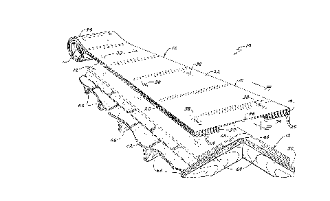
Figure 1 is a perspective view of the spiral rolled roof vent of this
invention
being partially installed on the peak of a roof;
Figure 2 is a cross sectional view of one vent part and the top panel of the
roof
vent, taken through line 2-2 in Figure 1, showing the double-faced corrugated
plastic
sheet material, hinged interconnections between the panels, and use of a
fastener to
secure the panels together in a vertically aligned stacked orientation;
Figure 3 is a diagrammatic representation of a section of the roof vent being
passed along a non-linear path between tensioning rollers and rolled onto a
cylindrical
drum or mandrel to form a tight spiral;
Figure 4 is a broken away perspective view showing the leading edge of the
section of Figure 3 being engaged by the cylindrical drum, and the multiple
layers of
double-faced corrugated plastic sheet material forming the panels of one vent
part and
top panel; and
Figure 5 is a perspective view of the roof vent rolled in a tight spiral or
coiled
configuration, with a label wrapped about the circumference of the roll, and
the roll
secured using a pair of bands.
DETAILED DESCRIPTION OF THE PREFERRED EMBODIMENTS
The apparatus and method of this invention are illustrated in Figures 1-5 and
referenced generally therein by the numeral 10.
The prior art disclosures relating to the fabrication and structure of roof
vents
using corrugated plastic sheet material having a convoluted intermediate ply,
the nick-
Sa
CA 02233271 2003-04-15
scoring and cut-scoring procedures utilized to construct folded roof
ventilators, and
the various other features, optional components, improvements, and methods of
fabrication and use associated with these products are incorporated into this
specification by reference as though fully recited herein, including but not
limited to
the disclosures contained in U.S. Patent No. 4,803,813 to Fiterman; U.S.
Patent Nos.
5,094,041 and 5,331,783 to Kasner; U.S. Patent No. 5,304,095 to Morris; and
U.S.
Patent No. 5,651,734 relating to a rolled ridge ventilator; U.S. Patent No.
5,946,868
filed on September 24, 1993 and issued September 7, 1999, relating to an
adjustable
air deflector for a roof ventilator; and United States Patent No. 5,947,817,
issued
September 7, 1999 relating to a foam end closure or intermediate support for a
roof
ventilator and method of making and using the same.
While the particular embodiment of the roof vent 10 described herein and
shown in Figures 1 and 2 is discussed below with particular reference to a
three-ply or
double-faced corrugated plastic sheet material, it is understood that roof
vents 10 of
this type and configuration may alternately be fabricated and constructed in
the same
manner using two-ply or single-faced corrugated plastic sheet material, as
well as
corrugated sheet materials of other types to the extent they are sufficiently
impervious
to weather, heat, moisture, decay, and other environmental conditions
prevalent in the
locations where the roof vents 10 will be installed and used.
Refernng particularly to Figures 1 and 5, the rolled roof vent 10 of this
invention is shown in its tightly-rolled spiral or coiled configuration for
shipping, and
in the process of installation. The roof vent 10 is shown as a section 12
having a finite
length on the order of 20', however the respective length and width of the
section 12
may be readily varied according to the needs of a particular application
discussed
further below. The section 12 has a leading edge 14 prior to being rolled, a
free end
16 after being rolled, and a pair of opposing sides 18, 20 which extend
parallel with
the longitudinal axis of the section 12 the length of the section 12.
The construction or fabrication of the section 12 from a blank of sheet
material
is shown in detail in Figure 2, as well as in Figures 1 and 4. The sheet
material is an
polyethylene plastic, and may include any percentage of recycled plastic resin
that is
suitable for the intended use. The section 12 defines a top panel 22 that
extends in an
uninterrupted manner the length of the section 12 generally parallel with and
bisected
by a longitudinal centerline. Extending from and hingedly connected to the top
panel
5b
CA 02233271 2003-04-15
22 are a plurality of panels 24, with three such panels 24 being shown. The
top panel
22 and plurality of panels 24 are preferably fabricated from a double-faced
corrugated
plastic sheet material having a pair of planar plies 26 connected to a
convoluted
intermediate ply 28 to create a multiplicity of air passages 30 and a grain
extending
generally perpendicular to the longitudinal axis of the section 12.
Each panel 24 is hingedly interconnected to the adjacent panels 24 or to the
outer edges of the top panel 22 by a hinge member 32 formed by one of the
planar
plies 26 which is not entirely cut or severed during the cutting and scoring
process.
The panels 24 are accordion folded into a generally stacked orientation
beneath the
top panel 22 to form a pair of opposing
Sc
CA 02233271 1998-03-26
vent parka 34, in each of which the panels 24 have approximately the same
shape and size and the
peripheral edges of each are in generally vertical alignment with one another.
A center route 36
may be formed into the underside of the top panel 22 in a conventional manner
as described in
the Kasner '041 patent identified above. 7:'he route 36 permits the top panel
22 to be folded or
conform to any pitch or angle, as well as rounded peaks, while maintaining a
uniform and
straight fold or bend. The route 36 permits the top panel 22 to provide
additional ventilation.
The panels 24 of the opposing vent parts may optionally be cut and scored to
form a staggered,
tapered, stepped, or other patterns or configurations other than vertical
stacked alignment along
same-sized concentric peripheral borders. The blank of sheet materials may
optionally be
fabricated from single-faced corrugated material having a single planar ply
attached to a
convoluted ply.
Referring to Figures 1 and 2, it may be seen that the panels 24 of the vent
parts and the
top panel 22 are fastened together (at approximately 2' intervals in a 20'
section 12) with staples
38 or similar fasteners. It may be appreciated that the vent parts may also be
fabricated by
cutting entirely through the blank to form a plurality of panels 24 which are
separate and
disconnecaed from one another, stacking those panels 24 to form the vent
parts, and fastening
them togfaher (and to the top panel) in stacked alignment or a staggered
pattern to form the vent
parts and the roof vent 10. In the preferred embodiment, the panels 24 and top
panel 22 are
interconnected both by the cut- or nick-sco:cing process which provides
integral hinges 32
between the plurality of panels 22 and the top panel 24, as well as the
fasteners 38.
The process of rolling the section 1:? into the spiral configuration is shown
diagrammatically in Figures 3 and 4. The leading edge 14 of the section 12 is
engaged on a
generally cylindrical drum 42 in any suitable manner, such as by a bar-type
clamp (not shown)
which extends parallel with and grips the leading edge 14 of the section 12, U-
shaped connectors
44 which are received within the air passages 30 of the section 12, or other
types of gripping
mechanisms conventionally used with single- or double-faced plastic sheet
material.
The pair of generally U-shaped connectors 44 shown in Figures 3 and 4 as one
of the
available ;gripping mechanisms is suited to corrugated sheet materials, each
connector 44 having
a pair of prongs 46 and an intermediate bridge 48, one of the prongs 46 being
received within an
aperture 50 in the side of the drum 42, and t:he other prong 46 received
within and engaging one
6
CA 02233271 1998-03-26
of the multiplicity of air passages 30 defined by the corrugated sheet
material. The prong 46
received within the aperture 50 of the drum 42 may be elongated relative to
the other prong 46,
and be spring biased toward the midpoint of the drum 42 so that the connector
44 may be pulled
laterally away from the drum 42 to disengage the section 12, and biased back
into engagement
with another section 12 by the spring force.
Referring particularly to Figure 3, the drum 42 is mounted for rotation in the
direction
that the section 12 is to be rolled into a spiral configuration, and may be
rotated manually or by a
suitable motor or drive mechanism (not shown). In addition, the drum 42 is
mounted to move
upwardly and downwardly between a lower and a raised position, as shown in
solid lines and
phantom lines, respectively, in Figure 3. As the drum 42 is rotated and the
section 12 rolled onto
the drum 42, the drum 42 will rise proportionately, such that the upper or
raised position
corresponds to a change in height equal to the radial thickness of the roof
vent 10 in the rolled
configuration, measured between the inner and outer diameters.
The section 12 being rolled is initially passed between a pair of pinch-type
tensioning
rollers 40 disposed on opposing top and bottom sides of the section 12 which
maintain the proper
alignment and longitudinal tensioning of the section 12 as it approaches the
dmm 42, and serves
to prevent the trailing end of the section 12 from flipping upwardly or around
the drum 42 as it
rotates due to natural stiffness or rigidity of the fabricated section 12. The
tensioning rollers 40
also exert sufficient rearward tension or force to ensure that the section 12
rolls into a reasonably
tight and uniform spiral. Alternately, in situations where the section 12 is
especially thick or the
corrugated sheet material is particularly stiff or rigid and a suitably tight
and uniform spiral roll
cannot be achieved using just pinch-type tensioning rollers 40, the section 12
may be passed
along a non-linear path between and across a plurality of tensioning rollers
40 disposed above
and below the section 12, and onto the drum 42 or mandrel as shown in Figure
4. In this process,
the tensioning rollers bend or flex the section from its normally planar
configuration to an angled
position, and thereby prepare the section 12 for rolling into a spiral
configuration. The
tensioning rollers may be disposed to gradually increase the angle of flexure
of the section 12,
for example the first roller 40 generating an obtuse bend of between
90° and 180°, and the
second roller 40 creating a bend of a lesser obtuse angle or approaching or
achieving a right or
acute angle. Subsequent angles may be the same or progressively sharper,
depending upon the
7
CA 02233271 1998-03-26
thickness of the section, stiffness of the corrugated sheet material, the
engagement between the
panels 24 and top panel 22, and the eventual diameter of the spiral to be
formed.
It will be readily appreciated by those skilled in the art that the weight of
the drum 42, the
rotational force or torque exerted on the section 12 by the drum 42, the
longitudinal tension
applied by the tensioning rollers 40, the spacing of the tensioning rollers 40
and the non-linear
path and angles of flexure formed therebetween, and the angular velocity of
the drum 42 will
depend upon the thickness and stiffness of the section 12, which in turn
depends upon the
particular construction and materials utilized. It has proven suitable to roll
a 20' section 12
constructed using nick-scored accordion folded panels 24 stapled along the
center of each vent
part at 2' intervals having a thickness of 5/8" into a tight spiral on an
approximately 12" diameter
drum 42. It should be noted that to produce a uniform tight spiral without
significant creases or
puckers, it is important to maintain generally uniform longitudinal tension
along each side edge
18, 20 of the section 12 as the section 12 traverses the non-linear path, at
least through the last
few or final pair of tensioning rollers 40.
Once the section 12 has been rolled into the tight spiral as shown in Figure
5, a label 52
or other F>lacard may be wrapped around a portion of the roof vent 10, and the
roof vent 10 may
be secured in the spiral configuration for shipping or storage using a pair of
welded plastic bands
54 or similar fasteners. The roof vent may ~~lso be shrink-wrapped, taped, or
secured in any other
suitable manner. Labeling information may optionally be printed or applied
directly to the outer
surface o:Fthe rolled roof vent 10.
It may be readily appreciated that the length of the section 12 may vary
anywhere
between a minimum length shorter than which it would not be practical to roll
the section 12 into
a spiral configuration to facilitate transport or storage, and a maximum
length beyond which the
spiral roll 10 could not practically be carried, lifted, or handled by a
worker installing the roof
vent 10 on a roof 58. However, in some applications (such as buildings having
very long peaks
or adjacent buildings having commonly aligned peaks) it may be suitable to
fabricate extremely
large spir;~l rolls 10 which are lifted to the roof 58 and deployed using
mechanical assistance,
such as a fork lift or boom crane. It may also be appreciated that the roof
vent 10 may be
fabricated in a variety of widths, thicknesses, and other dimensional
variances.
8
CA 02233271 1998-03-26
Referring again to Figure 1, the method of installing the roof vent 10 is
shown. The
installation site provides a house or other building structure having a
generally peaked roof 58
defining a ridge opening 60 extending therethrough for ventilation. All or a
portion of the roof
58 may be covered with shingles 62, and the roof 58 will usually include
planar underlayment 64
supported by joists 66 and a central beam (not shown).
The rolled roof vent 10 is placed on top of the peak of the roof 58 with the
free end I 6
extending across the top of the roll and oriented facing the end of the roof
58, or conversely
facing away from the direction of installation. When viewed from the side
elevation, the rolled
roof vent 10 will have a free end 16 extending over the top of the roll 10
when the direction of
installation is from right to left and the spiral of the roll 10 has a counter-
clockwise orientation,
as shown in Figure 1. In this manner, the rolled roof vent 10 may be handled
and installed by
one individual without the roll 10 inadvertently unrolling as sequential
portions of the section 12
are unrolled and secured to the roof.
The free end 16 of the rolled roof vent 10 is positioned adjacent the edge of
the roof 58 or
at another desired starting point with the roll disposed above the roof
opening 60, and the section
12 is then unrolled a short distance along the peak of the roof 58 to feed or
expose a manageable
portion, as shown in Figure 1. The free end 16 of the section 12 is then
fastened to the roof 58 in
a conventional manner using fasteners (not shown) such as nails or staples,
and an intermediate
portion between the free end 16 and the roll may similarly be secured to the
roof 58.
The section 12 is then further unrolled to expose another subsequent portion
of the
section 12, which is similarly secured to the roof 58. This process is
repeated until the desired or
entire length of the section 12 has been unrolled and secured to the roof 34.
Any excess length of
the section 12 may be cut away and discarded or used on a separate section of
the roof 58. It
may be appreciated that the roof vent 10 is generally very flexible across the
centerline of the top
panel 22, but a sufficient length of the section 12 may need to be unrolled to
allow enough
distance or clearance from the remaining portion of the roll to permit the top
panel 22 to be
flexed or bent so that the vent parts will contact the roof 58.
Alternately, the entire section 12 may be unrolled onto the peak of the roof
58 at one
time, generally aligned along the ridge or peak of the roof 58, and then
folded across the peak of
9
CA 02233271 1998-03-26
the roof 58 and secured to the roof 58 using fasteners in a conventional
manner traversing
progres:cively from one end of the section 12 to the other.
Foam end caps 68 or intermediate supports and adjustable air deflectors (not
shown) may
optionally be installed in a conventional rr~anner if desired, either during
or subsequent to the
installation of the rolled roof vent 10. A pair of the foam end caps 68 which
conform to the
shape or pitch of the roof 58 may be packaged between wrapped layers of the
rolled vent 10, and
additional foam segments 68 may be included if intermediate support for the
top panel 22 may be
desired in a particular application. More than one section 12 of the roof vent
10 may be butted
together with no special fasteners or connectors, or an installer may prefer
to adhere the foam end
caps 68 into each of the adjacent abutting sections 12 and then adhere or
caulk the end caps 68
and corrc°sponding abutting portions of the top panels 22 together to
provide a moisture-proof or
leak-resistant seal.
although the present invention has thus been described in detail with
reference to the
preferred. embodiments for practicing that invention, other embodiments,
modifications,
alterations, or substitutions deemed within the spirit and scope of the
present invention may
suggest themselves to those skilled in the art depending upon the particular
applications
involved. It is therefore intended that the present invention be limited only
by the properly
attributable scope of the attached claims below.
~Il-lat is claimed is: