Note : Les descriptions sont présentées dans la langue officielle dans laquelle elles ont été soumises.
CA 02236704 1998-0~-0~
DIFFERENTIAL UNIT WITH OPTIMIZED ASSEMBLY
WINDOW GEOMETRY
BACKGROUND OF THE INVENTION
The present invention relates generally to automotive differentials and,
more particularly, to a differential case having an optimized geometry for the
assembly windows formed therein.
Differentials are used in the drivetrain of motor vehicles for delivering
drive torque to the wheels while permitting speed differentiation therebetween.
F~eferring to FIGS. 1 and 2, a prior art differential 10 is shown to include a
differential case 12 supported at its opposite axial ends by bearing assemblies 14
fbr rotation relative to a differential carrier or housing 16. Housing 16 can be part
of an axle assembly of the type used in rear-wheel drive vehicles or, in the
allternative, can be incorporated into the transaxle of a front-wheel drive vehicle.
C)ifferential case 12 is formed to include an enlarged interior chamber 18 within
which a gearset is retained. Differential case 12 also includes a pair of first
alpertures 2t) and a pair of second apertures 22, with both pairs of apertures
communicating with chamber 18. In addition, differential case 12 includes a radial
fllange 24 to which a ring gear 26 is secured, such as by bolts 28. A pinion shaft 30
extends between first apertures 2() and is rigidly fixed to differential case 12 by a
locking pin 82 retained in a bore 33.
The gearset includes a pair of pinion gears 34 which are supported on
pinion shaft 30 within chamber 18 for rotation about its longitudinal axis, denoted in
F:IG. 1 by construction line "A". Each pinion gear 34 is meshed with a pair of side
CA 02236704 1998-0~-0~
gears 36 which, in turn, are each journally supported for rotation about the
longitudinal axis of differential case 12, denoted by construction line "B". The axial
e!nds of differential case 12 define a pair of tubular hubs 38 and 40 which journally
support a pair of axle shafts 42 and 44, respectively, and upon which bearing
5 a,ssemblies 14 are mounted. One end of axle shaft 42 is fixed (i.e., splined) to one
of side gears 36 while its opposite end is fixed to one of the vehicle's wheels.
';imilarly, one end of axle shaft 44 is fixed (i.e., splined) to the other one of side
gears 36 whlle its opposite end is fixed to the other of the vehicle's wheels. As is
conventional, ring gear 26, and differential case 12 to which it is attached, are
10 n~tated within housing 16 by an input drive pinion (not shown) which is secured to
tl1e end of a drive shaft (not shown). As such, rotary motion of case 12 is delivered
to axle shafts 42 and 44 through engagement of pinion gears 34 and side gears 36
to permit relative rotation therebetween.
According to the conventional assembly process for differential 10, side
gears 36 and then pinion gears 34 are sequentially assembled into chamber 18 by
passing them through second apertures 22, hereinafter referred to as assembly
windows. Referring to FIG. 2, one of assembly windows 22 is shown to be generally
elliptical in shape with an axial dimension "X" and a circumferential or lateral
dimension "Y". A significant design constraint is that lateral dimension "Y" has
20 traditionally been greater in size than the outer diameter of side gears 36 so as to
allow entry thereof into chamber 18 and to permit subsequent alignment of side
gears 36 relative to rotary axis "B". Similarly, axial dimension "X" must be greater
CA 02236704 1998-0~-0~
in size than the outer diameter of pinion gears 34 to permit entry thereof into
chamber 18 and subsequent alignment in meshed engagement with side gears 36.
Thereafter, pinion gears 34 are rotated into alignment with first apertures 20 for
receipt of pinion shaft 30. Due to this window geometry, design compromises are
5 required since barrel segment 48 of differential case 12 must be thick enough to
withstand the! maximum bending stresses that are anticipated to be applied thereon
during the service life of differential unit 10 while still maintaining the smallest outer
diameter (i.e., ring gear pilot diameter) as possible. Moreover, the material of choice
h;as previously been limited to fern~us materials such as, for example, cast iron to
10 accommodate these bending stresses.
SUMMARY OF THE INVENTION
Based upon the foregoing, there is a need to provide an optimized
geometry for the assembly windows in the differential case which facilitates easy
assembly of the gear components while improving the structural and functional
15 clharacteristics of the differential case. It is therefore an object of the present
invention to provide a geometry for the assembly windows of the differential case
which overcomes the deficiencies of the prior art.
It is a further object of the present invention to provide assembly
windows in a differential case wherein the geometry or shape of the assembly
20 windows is al function of the pinion gear diameter plus a minimum clearance.
CA 02236704 1998-0~-0~
As a related object, the assembly windows can have a lateral
dimension tl1at is less than the axial dimension.
As another object of the present invention, the differential case includes
a generally spherical chamber within which the pinion gears and side gears are
5 retained.
A yet further object is to provide a system for locating and retaining
tlhrust plates against the spherical chamber wall surface to permit rotation of the side
gears relative thereto.
BRIEF DESCRI PTION OF THE DRAWINGS
The above and further objects and advantages of the invention will
blecome apparent to those skilled in the art from the following detailed description
of the best mode currently contemplated for the preferred embodiment, when
considered in light of the accompanying drawings and claim wherein:
FIG. 1 is a sectional view of a conventional differential unit incorporated
into a motor vehicle axle assembly;
FIG. 2 is a side view of a differential case similar to that used with the
differential unit shown in FIG. 1;
FIG. 3 is a side view of a differential case according to a preferred
embodiment of the present invention;
FIG. 4 is an opposite side view of the differential case shown in FIG.
3;
CA 02236704 1998-0~-0~
FIG. 5 is a top view of the differential case shown in FIG. 3;
FIG. 6 is a sectional view taken generally along line 6-6 of FIG. 5;
FIG. 7 is a sectional view taken generally along line 7-7 of FIG. 3;
FIG. 8 is a plot of maximum bending stress for a predetermined loading
5 condition versus the window height of the differential case assembly windows; and
FIG. 9 is an exploded perspective view of a differential unit
incorporating the differential case of FIGS. 3 through 7 and which further
incorporates additional novel features.
DETAILED DESCRIPTION OF THE INVENTION
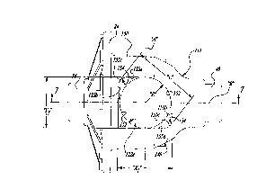
Referring now to the drawings, and specifically to FIGS. 3 through 7,
c3 differential case 112 is shown which is a modified version of differential case 12
shown in FIC,. 2 and which can be used in substitution thereof in differential unit 10
to provide various structural advantages. For purposes of comparison, like
reference numerals are used hereinafter to identify those components or elements
15 of differential case 112 which are similar to those previously described.
In general, differential case 112 has a pair of assembly apertures or
windows 127a and 122b, shown respectively in FIG. 3 and 4, having a modified
geometry compared to assembly window 22 of FIG. 2. More particularly, assembly
windows 122a and 122b have an axial dimension "X,", and a lateral dimension "Y,".
20 One advantage of the present invention resides in the fact that "Y," is less than "Y"
CA 02236704 1998-0~-0~
such that the circumferential portion of barrel segment 148, hereinafter referred to
als web portion 150, located between assembly windows 122a and 122b is wider
than previously available. Such additional width effectively reduces the maximum
blending stress acting on barrel segment 148 of differential case 112 which, in turn,
5 may permit the use of reduced casing thickness and/or the use of alternative
materials having lower fatigue characteristics such as, for example, aluminum or
magnesium. A plot comparing thls maximum bending stress for a given loading
condition of ;a conventional differential case 12 having a window lateral dimension
"Y" of about 85 mm and differential case 112 having a window lateral dimension "Y1"
10 of about 63 mm is shown in FIC,. 8. As is apparent, the stress reduction is
significant.
Referring again to Fl(,S. 3 and 4, assembly windows 122a and 122b
are contoured to be reverse mirror imaged, each having a pair of opposed circular
edge portions 152 interconnected by a pair of opposed elongated edge portions 154.
Elongated edge portions 154 are each defined by a first edge segment 155a
interconnected to a second edge segment 155b by an arcuate segment 155c. To
minimize the size of lateral dimension "Y1", first edge segment 155a of each edge
portion 154 iis substantially paralle!l to central axis "B". The radius "R" for edge
portions 152 is shown originating from the intersection of the "A" and "B" rotary axes
20 associated with differential case 112. Phantom lines clearly indicate the deviation
of elongated edge portions 154 a~ay from the radius "R". In fact, radius "R" is
slelected to be only slightly larger than the radius of pinion gears 34 to account for
CA 02236704 1998-0~-0~
the clearance required during assembly thereof into differential casing 112.
~I/loreover, the greatest overall length "L" of assembly windows 122a and 122b is
generally equal to the lateral dimension "Y" associated with differential case i 2. The
geometry or shape of assembly windows 122a and 122b was selected to permit side
5 gears 36 to be initially angulated relative to rotary axis "B" during assembly into
c:hamber 11B and subsequently aligned relative thereto.
Referring now to FIIG. 6, a sectional view of differential case 112
illustrates chamber 118 as being partially spherical, as defined by opposite edge
s,urfaces 156a and 156b. Chamber 118 communicates with a pair of axial bores 158
alnd 160 aligned along axis "B". Axial bore 158 includes a first segment 162
adapted to receive axle shaft 42 therein and a second segment 164 adapted to
r,eceive an axial hub segment of side gear 36 therein. Second segment 164 has a
greater diameter than first segment 162 and functions to properly seat side gear 36
rlslative to chamber 118 and axial bore 158. In a like manner, axial bore 160
includes a first segment 166 adapted to receive axle shaft 44 and a second segment
168 adapted to receive an axial hub segment of the other side gear 36 therein.
Finally, FIG. 7 is provided to show the variable thickness of barrel segment 148 of
differential case 112 in relation to assembly windows 122a and 122b. It will be
understood l:hat a designer can select either variable or constant thicknesses for
20 barrel segment 148 as is required for the particular differential case application.
Referring now to FIG 9, a preferred construction for a differential 110
is shown which includes differentiall case 112 discussed above. As seen, a pair of
CA 02236704 1998-0~-0~
lateral circular grooves 170 are forrned in spherical chamber 118 which are located
on opposite sides of axial bores '158 and 160 and are each aligned on a plane
substantially parallel to a vertical plane taken along the axial centerline of differential
casing 112. Side gears 36 are shown to include a front gear segment 172, a rear
thrust face 174, and an axial hub 176. Internal splines 178 formed in hub 176 are
provided fomrneshed engagement with corresponding external splines on the axle
shafts. Rear thrust face 174 is partially spherical in contour and is configured to
match the splherical contour of chamber 118. Conical thrust plates 180 are used
between chalmber 118 and each side gear 36 to absorb thrust loading and provide
a hardened sliding surface against which each side gear 36 can rotate. Thrust
pllates 180 include an axial hub 182 which is adapted to concentrically surround axial
hub 176 of side gear 36. Thrust plates 180 are retained in chamber 118 in a non-rotational or substantially limited rotational manner within segments 164 and 168 of
axial bores 1 !58 and 160, respectively. To provide means for retaining thrust plates
180 within chamber 118, each thrust plate 180 includes a set of circumferentially-
spaced projections or dimples 184 which are adapted to nest within grooves 170.
Preferably, four dimples 184 are provided on each thrust plate 80 such that two
dimples 184 are retained in each groove 170. Thus, thrust plates 180 are, once
assembled, prevented from rotating with side gears 36 relative to housing 16.
Advantageously, grooves 170 can be machined during the spherical chamber
machining operation and, as such, do not add cost to the differential case 112.
Finally, diffen~ntial 110 is shown to include pinion gears 34 each having a front gear
- 8 -
CA 02236704 1998-0~-0~
segment 18l~, a rear thrust face 188, and a bore 190 adapted to receive pinion shaft
:30 therein. Conical thrust plates 192 are also used in association with pinion gears
:34 to provid~e a hardened sliding surface relative to case 112. While not required,
lhrust plates 192 could be retainecl in case 112 in a manner similar to that used for
5 retaining thrust plates 180.
The optimized assernbly window geometry detailed above provides
several advantages over conventional differential cases. First, it is possible to
reduce the rnaximum bending stress compared to conventional elliptical window
geometry. INext, it permits maintenance of the same tooling clearances for the
10 spherical radius machining operation as required for cases having the elliptical
vvindow geometry. It also maintains the same core box parting line (a plane
bisecting the! spherical chamber which is perpendicular to the ring gear centerline)
as well as maintaining the optimal location of the centroid (on the ring gear
centerline) of all sections cut perpendicular to the ring gear centerline. These and
15 c~ther advantages permit a concomitant reduction in differential case wall thickness
and/or use of a lower fatigue type of material.
The foregoing discussion discloses and describes various embodiments
of the present invention. One skiilled in the art will readily recognize from such
discussion, and from the accompanying drawings and claims, that various changes,
20 modifications and variations can be made therein without departing from the true
spirit and fair scope of the invention as defined in the following claims.