Sélection de la langue

Search

Sommaire du brevet 2241699 

Énoncé de désistement de responsabilité concernant l'information provenant de tiers

Une partie des informations de ce site Web a été fournie par des sources externes. Le gouvernement du Canada n'assume aucune responsabilité concernant la précision, l'actualité ou la fiabilité des informations fournies par les sources externes. Les utilisateurs qui désirent employer cette information devraient consulter directement la source des informations. Le contenu fourni par les sources externes n'est pas assujetti aux exigences sur les langues officielles, la protection des renseignements personnels et l'accessibilité.

Disponibilité de l'Abrégé et des Revendications

L'apparition de différences dans le texte et l'image des Revendications et de l'Abrégé dépend du moment auquel le document est publié. Les textes des Revendications et de l'Abrégé sont affichés :

  • lorsque la demande peut être examinée par le public;
  • lorsque le brevet est émis (délivrance).
(12) Brevet: (11) CA 2241699
(54) Titre français: CONNECTEUR AVEC DISPOSITIF DE PROTECTION CONTRE LES EMISSIONS ELECTROMAGNETIQUES RAYONNEES OU CONDUITES
(54) Titre anglais: CONNECTOR WITH PROTECTION FROM RADIATED AND CONDUCTED ELECTROMAGNETIC EMISSIONS
Statut: Périmé et au-delà du délai pour l’annulation
Données bibliographiques
(51) Classification internationale des brevets (CIB):
  • H01R 13/648 (2006.01)
  • H01R 13/658 (2011.01)
  • H03H 01/00 (2006.01)
  • H04B 15/02 (2006.01)
(72) Inventeurs :
  • CORTES, NESTOR EDUARDO (Etats-Unis d'Amérique)
(73) Titulaires :
  • OMEGA ENGINEERING, INC.
(71) Demandeurs :
  • OMEGA ENGINEERING, INC. (Etats-Unis d'Amérique)
(74) Agent: SMART & BIGGAR LP
(74) Co-agent:
(45) Délivré: 2006-01-03
(22) Date de dépôt: 1998-06-24
(41) Mise à la disponibilité du public: 1998-12-27
Requête d'examen: 2003-06-05
Licence disponible: S.O.
Cédé au domaine public: S.O.
(25) Langue des documents déposés: Anglais

Traité de coopération en matière de brevets (PCT): Non

(30) Données de priorité de la demande:
Numéro de la demande Pays / territoire Date
60/051,055 (Etats-Unis d'Amérique) 1997-06-27

Abrégés

Abrégé français

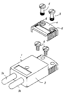
Cette invention fournit les connecteurs électriques, en particulier pour les dispositifs ayant un faible niveau de signal qui pourrait être affecté par des émissions électromagnétiques rayonnées ou conduites d'un champ de dispersion, par exemple des circuits capteur thermocouples. Le connecteur présente un élément à son extrémité pour être raccordé à un câble électrique, un élément de raccord pour un raccord électrique avec un élément conducteur correspondant, et un bloc de matière à base de ferrite, grâce auquel l'élément de raccord ou chaque élément de raccord est sollicité afin de fournir une protection complète par le matériau à base de ferrite contre les interférences par rayonnement électromagnétique.


Abrégé anglais

This invention provides electrical connectors, particularly for devices having a low signal level which might be adversely affected by stray radiated and/or conducted electromagnetic emissions, for example thermocouple sensor circuits. The connector has terminal means for attachment of an electrical lead, connecting means for engagement electrically with mating conductive means of an electrical component, and a block of ferrite material, through which the or each connecting means is engaged so as to provide complete protection by the ferrite material against interference by electromagnetic radiation.

Revendications

Note : Les revendications sont présentées dans la langue officielle dans laquelle elles ont été soumises.


-9-
CLAIM
1. An electrical connector comprising terminal means for attachment of
an electrical lead, connecting means for engagement electrically with mating
conductive
means of an electrical component, and a block of ferrite material through
which said
connecting means is engaged to provide protection by said ferrite material
against
interference by electromagnetic radiation.

Description

Note : Les descriptions sont présentées dans la langue officielle dans laquelle elles ont été soumises.


CA 02241699 1998-09-25
-1-
TITLE OF THE INVENTION
CONNECTOR WITH PROTECTION FROM RADIATED
AND CONDUCTED ELECTROMAGNETIC EMISSIONS
This disclosure contains no right to any inventions made under federally-
sponsored research and development.
BACKGROUND OF THE INVENTION
FIELD OF THE INVENTION
This invention relates generally to connectors, whether single conductor or
multiple conductor, and whether intended for use as single conductor items,
e.g. for making
a separable connection to a piece of electronic apparatus, or as a part or
parts of a multiple-
part line connector assembly, e.g. male and female interconnecting plug and
socket items.
More specifically, the invention relates to connectors which provide for
suppression of radiated and/or conducted electromagnetic emissions which would
be
detrimental to proper use of apparatus in which the connector is included. In
particular the
invention is applicable to fields of use wherein there is necessity for
including an electrical
or electronic circuit or device having a relatively low signal level which
might be adversely
affected by such stray emissions, for example thermocouple sensor circuits.

CA 02241699 1998-09-25
-2-
DESCRIPTION OF THE PRIOR ART
In the prior art of connectors there are disclosures of the use of ferrite
material
in the following:
(I) U.S. Patents assigned to AMP Inc. 4,699,590, 4,359,620, 3,789,263,
Re29,258, 3,735,705, 3,987,380, 4,936,800.
(II) U.S. Patent assigned to The Whitaker Core: 5,219,305.
(III) U.S. Patent William Baird Fritz 3,743,978.
(IV) U.S. Patent assigned to Stanford Research Institute and Amplex
Corporation:
3,533,948.
(V) Un-examined Japanese Patent Application, AMP Inc., 90-032246/05 JO 1279-
584-A discloses an electrical connector which has a noise filter with a
ferrite
head fitted to a terminal lead formed by a central conductor of a feed-through
capacitor.
(VI) German Patent assigned to AMP Inc., Auslegeschrift No. 2,058,419
discloses
a method for the manufacturer of a high frequency filter from a ferrite tube,
which is in the form of a highly compressed tube and which is bonded on its
outer surface with a covering of dielectric material, the layer of dielectric
material carrying an electrode in the form of a metallic outer sleeve, and a
further electrode is provided in similar manner on the inside of the ferrite
tube,
characterized in that the covering (6) of dielectric material is laid down
directly into the outer surface of the ferrite tube (5) by electrophoresis.

CA 02241699 1998-09-25
-3-
SUMMARY OF THE INVENTION
It is known that electrical signals carried by connectors, or adjacent
apparatus,
may be subject to electromagnetic interference as the result of induced
signals picked up
from the electromagnetic radiation of adjacent electrical equipment. Such
interference
results from the leads, to the connector or within the connector, acting as an
antenna which
senses stray electromagnetic radiation.
Various efforts have been made to avoid or suppress the result of such
interference, but such efforts have been found to be inconvenient and/or
expensive to
implement or both. For example, it has been found in the past that
interference from stray
signals can be avoided by encapsulating leads in sheaths of RFI (radio
frequency
interference shielding) material, or by determining the strength of nearby
stray signal fields
and then moving all such nearby sources to a physical distance from the leads
that has been
calculated to prevent possibility of undesired signals being picked up by
electromagnetic
induction. It can be seen, readily, that such preventive methods and
techniques are indeed
costly and inconvenient. Other attempts to reduce or avoid interference from
stray signals
have involved the use of ferrite cores. Hitherto such uses have in some cases
required
additional circuit elements, such as insertion of a jumper cable having a
permanently-
included ferrite core, in series with the main conductors in the circuit; or
awkwardly and
inconveniently surrounding one or more of the circuit conductors with
separately applied
ferrite cores. Again, it is known to use ferrite beads mounted conveniently on
circuit boards
or molded into connectors used with computer monitors.
It is established practice, in industries that make use of thermocouple
sensors,

CA 02241699 1998-09-25
-4-
to couple the sensor into a related electrical circuit by means of an
electrical connector.
When for example thermocouples are connected to instruments such as panel
meters,
controllers and transmitters, the input signal from the sensor of transducer
usually travels
substantial distances along fine gauge electrically conductive wire leads. The
length and
nature of such leads and the environment in which they must function often
create
conditions that favour occurrence of stray emissions. In many cases, the leads
or signal
wires from a sensor or thermocouple are first attached, for convenience, to an
electrical
connector, for coupling to an instrument or the like. As soon as the
conductors of the
connector are electrically coupled to the circuit, stray EMI emissions may be
conducted into
the circuit. Of particular importance are thermocouple connectors, which are
particularly
susceptible because of the long lead conductive path of the conductors
themselves and the
high input impedance of the instrumentation.
The term "ferrite" as commonly understood in the electronics field, denotes a
particular material having one or more oxides of iron in particulate form in a
carrier. This
usage of the term "ferrite" is to be distinguished from the usual dictionary
definition which
is a generic name for a number of oxides of iron. In this specification, the
term "ferrite" is
to be understood as including within its scope any suitable material having an
absorption
and/or shielding effect as concerns electromagnetic waves which may be emitted
at or
adjacent to a zone of completion of an electrical circuit. Known ferrite
elements consist of
ferrite material sintered into a convenient shape. Other known "ferrite"
materials for the
suppression of electromagnetic interference are nickel-zinc compositions and
manganese-
zinc materials, of different compositions to permit selection of an optimum
type for a given
application; pressed parts, components, and powders are known.

CA 02241699 1998-09-25
-5-
OBJECTS OF THE INVENTION
Accordingly it is an object of this invention to provide means associated with
an electrical connector that is capable of filtering stray signals which may
be induced in the
lead or leads of the connector.
It is another object of this invention to provide apparatus which eliminates
the
effects of undesired stray signals in circuits which include a connector or
connectors, that is
uncomplicated in design, and that is relatively simple and inexpensive to
produce.
It is still another object of this invention to provide means associated with
an
electrical connector, for eliminating the effects of undesired stray signals
in the circuit or
circuits in which the connector is included, that is easily adaptable to
single lead or multi-
lead connectors.
Another and further object of this invention is to provide means associated
with an electrical connector for eliminating the effects of undesired stray
signals in its
circuit or circuits, that can be manufactured easily in various configurations
to accommodate
differing circuit requirements.
And yet another and further objective of this invention is to provide means,
associated with an electrical connector, for the elimination of the effects of
undesired stray
signals in its circuit or circuits, which can be readily changed and
substituted in the
connector by other such means of a different rating or effectiveness according
to
requirement.
It has been found that so-called "soft" ferrite elements, as they are known in
this art, when properly included in an electrical circuit, act as an
electromagnetic "sponge"

CA 02241699 1998-09-25
-6-
to absorb and dissipate the unwanted electromagnetic wave energy of the
conductor or
conductors with which the ferrite element is associated.
BRIEF DESCRIPTION OF THE DRAWINGS
Figure 1 is a perspective elevation, with parts shown in separated condition,
of
a two-pin male plug suitable for connecting a lead (not shown) to a female
socket provided,
say, on another lead or on an article of apparatus;
Figure 2 is an underplan view of the plug of figure 1;
Figure 3 is a section, taken in a first plane, through the plug of figures 1
and 2;
Figure 4 is a section, taken on a second plane at right angles to the plane of
figure 3, of the plug of figures 1 and 2, with a cover portion omitted;
Figures 5 and 6 are respectively perspective views, of the plug of figures 1
and
2, seen from different angles, and with the cover portion omitted;
Figure 7 is an elevation of a female socket intended to co-operate with the
male plug of figures 1 and 2;
Figure 8 is a section, taken in a first plane, through the socket of figure 7;
Figure 9 is a section, taken on a second plane at right angles to the plane of
figure 8, of the female socket of figure 7, with a cover portion omitted;
Figures 10 and 11 are respectively perspective views, of the female socket of
figure 7, seen from different angles and with a cover portion omitted;
Figure 12 if a perspective elevation of a ferrite block, as seen also in
figures 3,
4, 8 and 9.

CA 02241699 1998-09-25
DETAILED DESCRIPTION OF THE INVENTION
Referring to figure 1 of the drawings, there is shown a male plug 1 having a
body 2 serving as a mounting for pins 3a and 3b of respectively different
diameters, so as to
ensure that the plug can only be interconnected with a socket in the correct
position. A
removable cover 4 can be secured in position on the plug body 2 by means of
fixing screws
5 passed through holes 6 in the cover 4 and engaging into threaded fixtures 7
in the body 2.
In the body 2, at a position below the cover 4 when it is attached, there are
provided
threaded terminals 8a and 8b to which wire leads can be attached by screws 9.
The
terminals form part of the respective pins 3a and 3b.
Within the body 2 there is housed a block 10 of ferrite material. The block 10
is provided with through passages 1 la, l lb of respectively different
diameters to permit
mounting through the block of the two pins 3a, 3b of the plug. Accordingly,
each of the
conductors (pins 3a, 3b) of the plug is totally surrounded by the ferrite
material, and the
block 10 can readily be made of suitable large dimensions to ensure that
proper shielding is
obtained. Referring now to figures 7, 8, 9, 10, 1 l and 12, there is shown a
female socket 12
which is largely similar in construction to the male plug 1 of figures 1 to 6,
except that the
pins 3a, 3b of the plug are replaced by tubular sockets 13a, 13b of
respectively different
internal diameters, adapted to receive the respective pins 3a, 3b of the male
plug. Here
again, the internal conductors of the socket (i.e. the sockets 13a, 13b) pass
through and are
entirely surrounded by the block 10 of ferrite material. It will readily be
appreciated that the
invention is not restricted to two-conductor plugs and sockets, but could be
used in single-
conductor items, or in items having more than two conductors, e.g. other
multiple pin plugs

CA 02241699 1998-09-25
_g_
and sockets. As the protection, by ferrite material, is provided by a simple
aperature block
(the block 10), it is possible to vary the composition of the material of the
block 10
according to need, and simply insert a block of appropriate composition for
the use
intended.
The block may be housed releasable in the body of the plug or socket, or may
be permanently included therein during the process of molding of the body.

Dessin représentatif
Une figure unique qui représente un dessin illustrant l'invention.
États administratifs

2024-08-01 : Dans le cadre de la transition vers les Brevets de nouvelle génération (BNG), la base de données sur les brevets canadiens (BDBC) contient désormais un Historique d'événement plus détaillé, qui reproduit le Journal des événements de notre nouvelle solution interne.

Veuillez noter que les événements débutant par « Inactive : » se réfèrent à des événements qui ne sont plus utilisés dans notre nouvelle solution interne.

Pour une meilleure compréhension de l'état de la demande ou brevet qui figure sur cette page, la rubrique Mise en garde , et les descriptions de Brevet , Historique d'événement , Taxes périodiques et Historique des paiements devraient être consultées.

Historique d'événement

Description Date
Inactive : CIB du SCB 2022-09-10
Le délai pour l'annulation est expiré 2015-06-25
Lettre envoyée 2014-06-25
Inactive : CIB expirée 2011-01-01
Inactive : CIB de MCD 2006-03-12
Accordé par délivrance 2006-01-03
Inactive : Page couverture publiée 2006-01-02
Préoctroi 2005-10-18
Inactive : Taxe finale reçue 2005-10-18
Un avis d'acceptation est envoyé 2005-04-25
Lettre envoyée 2005-04-25
Un avis d'acceptation est envoyé 2005-04-25
Inactive : Approuvée aux fins d'acceptation (AFA) 2005-03-09
Lettre envoyée 2003-07-11
Exigences pour une requête d'examen - jugée conforme 2003-06-05
Toutes les exigences pour l'examen - jugée conforme 2003-06-05
Requête d'examen reçue 2003-06-05
Lettre envoyée 1999-10-29
Inactive : Transfert individuel 1999-09-28
Demande publiée (accessible au public) 1998-12-27
Inactive : CIB attribuée 1998-09-25
Inactive : Correspondance - Formalités 1998-09-25
Symbole de classement modifié 1998-09-25
Inactive : CIB en 1re position 1998-09-25
Inactive : Certificat de dépôt - Sans RE (Anglais) 1998-09-09
Inactive : Demandeur supprimé 1998-09-03
Demande reçue - nationale ordinaire 1998-09-03

Historique d'abandonnement

Il n'y a pas d'historique d'abandonnement

Taxes périodiques

Le dernier paiement a été reçu le 2005-02-25

Avis : Si le paiement en totalité n'a pas été reçu au plus tard à la date indiquée, une taxe supplémentaire peut être imposée, soit une des taxes suivantes :

  • taxe de rétablissement ;
  • taxe pour paiement en souffrance ; ou
  • taxe additionnelle pour le renversement d'une péremption réputée.

Les taxes sur les brevets sont ajustées au 1er janvier de chaque année. Les montants ci-dessus sont les montants actuels s'ils sont reçus au plus tard le 31 décembre de l'année en cours.
Veuillez vous référer à la page web des taxes sur les brevets de l'OPIC pour voir tous les montants actuels des taxes.

Titulaires au dossier

Les titulaires actuels et antérieures au dossier sont affichés en ordre alphabétique.

Titulaires actuels au dossier
OMEGA ENGINEERING, INC.
Titulaires antérieures au dossier
NESTOR EDUARDO CORTES
Les propriétaires antérieurs qui ne figurent pas dans la liste des « Propriétaires au dossier » apparaîtront dans d'autres documents au dossier.
Documents

Pour visionner les fichiers sélectionnés, entrer le code reCAPTCHA :


Pour visualiser une image, cliquer sur un lien dans la colonne description du document. Pour télécharger l'image (les images), cliquer l'une ou plusieurs cases à cocher dans la première colonne et ensuite cliquer sur le bouton "Télécharger sélection en format PDF (archive Zip)" ou le bouton "Télécharger sélection (en un fichier PDF fusionné)".

Liste des documents de brevet publiés et non publiés sur la BDBC .

Si vous avez des difficultés à accéder au contenu, veuillez communiquer avec le Centre de services à la clientèle au 1-866-997-1936, ou envoyer un courriel au Centre de service à la clientèle de l'OPIC.


Description du
Document 
Date
(aaaa-mm-jj) 
Nombre de pages   Taille de l'image (Ko) 
Dessin représentatif 1999-01-17 1 7
Abrégé 1998-06-23 1 16
Revendications 1998-06-23 1 10
Description 1998-06-23 6 273
Dessins 1998-06-23 4 125
Abrégé 1998-09-24 1 16
Description 1998-09-24 8 270
Dessins 1998-09-24 5 105
Revendications 1998-09-24 1 10
Dessin représentatif 2005-12-01 1 9
Certificat de dépôt (anglais) 1998-09-08 1 174
Demande de preuve ou de transfert manquant 1999-06-27 1 112
Courtoisie - Certificat d'enregistrement (document(s) connexe(s)) 1999-10-28 1 115
Rappel de taxe de maintien due 2000-02-27 1 113
Rappel - requête d'examen 2003-02-24 1 120
Accusé de réception de la requête d'examen 2003-07-10 1 173
Avis du commissaire - Demande jugée acceptable 2005-04-24 1 162
Avis concernant la taxe de maintien 2014-08-05 1 172
Correspondance 1998-09-08 1 33
Correspondance 1998-09-24 16 443
Taxes 2003-06-02 1 30
Taxes 2001-06-20 1 34
Taxes 2002-06-19 1 35
Taxes 2000-06-22 1 46
Taxes 2004-03-18 1 33
Taxes 2005-02-24 1 28
Correspondance 2005-10-17 1 26
Taxes 2006-03-15 1 27